Latency in OTN and ZR/ZR+ Coherent Pluggables
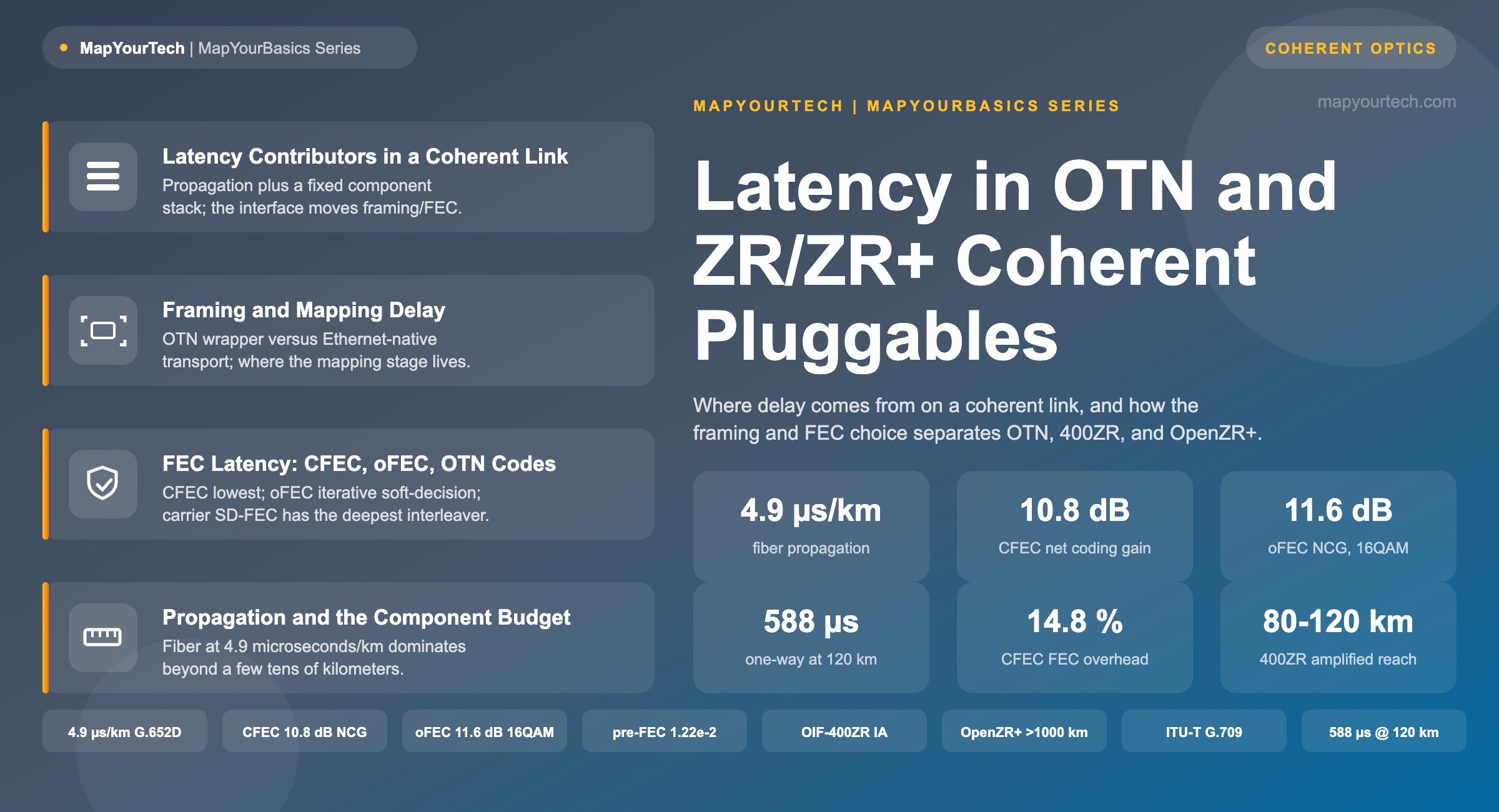
Where delay comes from on a coherent link, and how the framing and forward-error-correction choice separates carrier OTN, 400ZR, and OpenZR+.
Introduction
Two links carrying the same 400GbE service across the same 120 km of fiber can differ in end-to-end delay by several microseconds depending on how the signal is framed and which forward-error-correction (FEC) code the transceiver runs. That difference is invisible on a long-haul route, where fiber propagation sets the number, but it becomes the deciding factor on short data-center-interconnect (DCI) spans and on any link carrying delay-sensitive traffic. This article separates the delay a coherent link actually accumulates into its parts, then shows where the Optical Transport Network (OTN) wrapper, the 400ZR interface, and the OpenZR+ interface land on each part.
The three interfaces occupy different points on the same trade curve. Carrier OTN per ITU-T G.709 maps every client into an OPU/ODU/OTU hierarchy and runs a deep-interleaver code for maximum reach and full operations support. The Optical Internetworking Forum (OIF) 400ZR interface strips that framing down to Ethernet-native transport with a low-latency concatenated code for the DCI use case. OpenZR+ sits between them, keeping the small pluggable form factor while adding a stronger iterative code and optional OTN framing. Understanding how those choices move the delay budget is the same skill that lets an engineer place a coherent pluggable in a router faceplate through IP over DWDM without importing delay the application cannot absorb.
1. Latency Contributors in a Coherent Link
End-to-end one-way delay on a point-to-point coherent link is the sum of a distance term and a fixed component term. The distance term is fiber propagation. The component term is everything the electronics do at each end: client framing and mapping, FEC encoding, digital-signal-processing (DSP) functions in the modulator and demodulator, and FEC decoding. The framing and FEC choice controls two of those stages directly; the DSP cost and the propagation cost are close to fixed for a given module and route.
Coherent DSP carries a real, near-constant cost. The demodulator performs chromatic-dispersion compensation, polarization tracking, carrier recovery, and equalization in real time, every block adding delay measured in microseconds (vendor-typical, coherent DSP). A direct-detect module skips most of that processing and pays for it in reach — active electrical cable assemblies, for reference, add roughly 85 to 110 ns (vendor-measured). That gap is the reason over-specifying coherent optics on a short link imports delay for no benefit, a point examined in the power-per-bit case for router optics.
Table 1 separates the stack into its individual sources, states the mechanism that makes each one add delay, and marks which of them the interface and FEC choice controls versus which are fixed by distance or by the coherent design.
| Latency source | What it adds and why | Typical magnitude | Controlled by |
|---|---|---|---|
| Fiber propagation | Light travels at the vacuum speed divided by the fiber group index, so route distance sets a floor no electronics can remove. | 4.9 µs/km one-way (measured) | Route distance — fixed |
| Framing and mapping | OTN wraps the client into OPU/ODU/OTU and buffers it for justification; each wrap-and-buffer is a stage the signal must cross at both ends. | Present in OTN, removed in native-Ethernet ZR (standard) | Interface / framing choice |
| FEC coding | The encoder adds parity and the decoder must collect a full code block before it can correct — the stronger the code, the more it holds. | Scales with code strength (standard) | FEC choice |
| Interleaving depth | Interleaving spreads burst errors across many symbols, so the decoder waits for a complete interleaver block. CFEC is shallow; oFEC and carrier SD-FEC are deeper. | Deeper interleaver, more delay (standard) | FEC choice |
| Iterative soft-decision decoding | oFEC and carrier SD-FEC repeat decode passes — oFEC runs about three soft-decision iterations — to reach higher coding gain. | oFEC: a few µs combined encode + decode (published estimate) | FEC choice |
| Coherent DSP | Chromatic-dispersion compensation, polarization tracking, carrier recovery, and equalization each execute as real-time blocks in the DSP pipeline. | Microseconds, near-fixed per module (vendor) | Fixed for coherent |
| O-E-O regeneration and node hops | Every transponder regeneration point or ODU switch repeats the full framing, FEC, and DSP stack, so the component term multiplies per hop. | Component stack repeats per hop (measured) | Architecture |
| Legacy inline dispersion compensation | Pre-coherent links add a dispersion-compensating-fiber spool to cancel dispersion; the extra fiber is extra propagation. Coherent DSP removes the need for it. | ~100 µs per DCF module; 5–50 ns for FBG-based (measured) | Architecture — coherent removes it |
Takeaway: One-way delay = propagation (a function of distance) + a fixed component stack (framing, FEC, and DSP at both ends). The interface choice moves the framing and FEC stages; propagation and the core DSP cost stay put.
2. Framing and Mapping Delay
Carrier OTN wraps every client in the G.709 digital hierarchy. The client signal enters the Optical Payload Unit (OPU), gains path overhead as the Optical Data Unit (ODU), and gains section overhead and FEC as the Optical Transport Unit (OTU). Positive and negative justification bytes absorb the rate difference between the client clock and the line clock, which lets OTN carry the client asynchronously but adds a mapping and buffering stage the signal must pass through at each end. Beyond 100 Gb/s the line side uses OTUCn framing with FlexO interfaces, and ODU switching at intermediate nodes adds another mapping stage per hop where grooming is performed.
400ZR takes the opposite approach. It defines a 400GbE-only interface with no OTN wrapper, mapping Ethernet directly into the coherent DSP frame. Removing the OPU/ODU/OTU stages and the justification buffer removes their delay, which is one reason the OIF constrained 400ZR to the minimum feature set the DCI use case needs. The cost is the loss of OTN operations, administration and maintenance (OAM): standard ZR modules do not provide the tandem-connection monitoring, general communication channels, and per-container fault isolation that carrier OTN carries.
OpenZR+ keeps the Ethernet-native host interface but adds optional OTN framing (OTU4 and OTUCn) as a firmware and mapping function, so the same silicon can present as a low-overhead Ethernet interface or as a carrier-grade OTN line card. Choosing the OTN mode restores the monitoring and multiplexing an operator may need, and reintroduces the mapping stage that the pure-Ethernet mode avoids. The framing decision is therefore also a monitoring decision, examined further in the basics of IPoDWDM and in the guide to designing optical network architectures across services.
Takeaway: OTN framing buys asynchronous multi-service transport and full OAM at the cost of a mapping-and-justification stage. Native-Ethernet ZR removes that stage and its delay; OpenZR+ lets the operator turn it on only where the monitoring is needed.
3. FEC Latency Across CFEC, oFEC, and OTN Codes
FEC is where the three interfaces separate most clearly on delay, because stronger codes buy coding gain with deeper interleaving and more decoder iterations, and both add latency. The general relationship is fixed: soft-decision and iterative decoding provide higher net coding gain (NCG) than hard-decision codes at the same overhead, at the cost of more processing delay and power (established, ITU-T G-series literature).
The 400ZR interface uses concatenated FEC (CFEC): a hard-decision outer staircase code combined with a soft-decision inner Hamming code, at about 14.8 percent overhead, delivering about 10.8 dB NCG and correcting a pre-FEC bit-error ratio near 1.22 × 10⁻² to a post-FEC floor below 1.0 × 10⁻¹⁵ (standard-specified, OIF-400ZR Implementation Agreement). CFEC was chosen for the DCI application precisely because it reaches that gain with relatively low complexity and low latency.
OpenZR+ uses open FEC (oFEC), a block-turbo code with iterative soft-decision decoding — the OpenROADM implementation runs three soft-decision plus two hard-decision passes. oFEC delivers about 11.1 dB NCG for QPSK and about 11.6 dB for 16QAM at a pre-FEC BER threshold near 2.0 × 10⁻² (standard-specified, Open ROADM / OpenZR+ MSA) — roughly 0.3 dB (QPSK) to 0.8 dB (16QAM) higher net coding gain than CFEC's 10.8 dB, and it tolerates a higher pre-FEC BER than CFEC's 1.22 × 10⁻². That combination — a little more coding gain, a higher pre-FEC threshold, and the option to drop to QPSK or 8QAM — extends OpenZR+ reach beyond 1,000 km at reduced line rates. The extra iteration and deeper interleaving make oFEC's encode-and-decode latency higher than CFEC's, on the order of a few microseconds combined (published estimate). The full mechanism is covered in the MapYourTech treatment of open forward error correction, and the way the pre-FEC threshold sets alarm baselines is covered in pre-FEC BER trend windows.
Legacy carrier OTN spans the widest range. The original G.709 out-of-band code is Reed-Solomon RS(255,239) with 16-byte interleaving, about 7 percent overhead and 5.6 dB NCG (standard-specified, ITU-T G.709/G.975). Carrier-grade coherent OTN line cards run far stronger soft-decision codes with larger overhead and deeper interleavers to reach long-haul and submarine distances, and those deeper interleavers are the source of the highest component latency of the three interface classes.
Ttotal = Tprop + Ttx + Trx

Tprop = (ng × L) / c  ≈  4.9 µs/km × L

Where:
  Tprop = one-way fiber propagation delay
  Ttx, Trx = component stack each end (framing + FEC + DSP)
  ng = group refractive index (≈ 1.4682, SMF-28 at 1550 nm)
  L  = fiber length (km)
c = speed of light in vacuum (299,792,458 m/s)| Attribute | Carrier OTN | 400ZR | OpenZR+ |
|---|---|---|---|
| Framing | G.709 OPU/ODU/OTU + justification | Ethernet-native, no OTN wrapper | Ethernet; optional OTU4/OTUCn |
| FEC scheme | RS(255,239) legacy; deep SD-FEC on modern line cards | CFEC (staircase + Hamming) | oFEC (block turbo, iterative SD) |
| FEC overhead | ~7% (RS) up to ~15–25% (SD) | ~14.8% | ~15.3% |
| Net coding gain | 5.6 dB (RS) up to higher for SD codes | ~10.8 dB | ~11.1 dB QPSK / ~11.6 dB 16QAM |
| Component latency | Highest (deep interleaver + mapping) | Lowest | Moderate (oFEC a few µs enc + dec) |
| Reach | Metro to long-haul and submarine | 80–120 km amplified; ~40 km unamplified | >1,000 km at reduced line rates |
| Modulation | Various (vendor line cards) | DP-16QAM fixed | QPSK / 8QAM / 16QAM |
| Client support | Multi-service (Ethernet, FC, SDH, OTN) | 400GbE only | 100 / 200 / 400GbE |
| Monitoring | Full OAM, TCM, GCC | Basic | Enhanced; full OTN in OTN mode |
Takeaway: CFEC gives the lowest FEC delay for the DCI reach. oFEC adds about 0.3 to 0.8 dB of net coding gain plus a higher pre-FEC threshold for regional reach, at a few microseconds of combined encode-and-decode latency. Carrier OTN's long-haul codes give the most gain and the most delay.
4. Propagation Delay and the Component Budget
Fiber propagation sets the scale of the whole budget. Light in standard single-mode fiber travels at the vacuum speed divided by the group refractive index, about 1.4682 for SMF-28 at 1550 nm, giving roughly 4.9 µs/km one-way — near 10 µs/km round trip (measured/standard). At 120 km, the amplified DCI reach boundary, one-way propagation is 120 × 4.9 = 588 µs, against which a few microseconds of CFEC-plus-DSP component delay is under about one percent of the budget. This is the reasoning behind the 5-microsecond-per-kilometer rule.
| Link reach | One-way delay (µs) | Round-trip (µs) |
|---|---|---|
| 40 km | 196 | 392 |
| 80 km | 392 | 784 |
| 120 km | 588 | 1,176 |
| 300 km | 1,470 | 2,940 |
| 600 km | 2,940 | 5,880 |
| 1,000 km | 4,900 | 9,800 |
The consequence is a clean split by distance. On any link beyond a few tens of kilometers, the interface choice changes total delay by well under a percent, so reach, coding gain, monitoring, and power decide the selection. On sub-100 km DCI spans the component stack is a larger fraction of a smaller total, so the CFEC-versus-oFEC and Ethernet-versus-OTN decisions become measurable. On a 40 km unamplified span the 196 µs propagation term still leads, but a few microseconds of avoidable framing and FEC delay is now a real slice of the budget for the applications that count microseconds.
Takeaway: Beyond tens of kilometers, propagation at 4.9 µs/km dominates and the interface choice is a rounding error on delay. Under 100 km, and in delay-critical traffic, the framing and FEC delta is worth optimizing.
5. Design Considerations for Delay-Sensitive Links
Match the interface to the reach rather than to the spec sheet. For a sub-120 km DCI link carrying 400GbE, 400ZR with CFEC gives the lowest component delay and full multi-vendor interoperability, and adding OTN framing or oFEC on such a span imports delay and overhead the link does not need. For metro and regional reach where a single 400ZR span cannot close the optical-signal-to-noise-ratio budget, OpenZR+ with oFEC buys the extra coding gain and higher pre-FEC threshold for a bounded, few-microsecond delay cost on the code, and the reach-versus-rate trade is set out in this link-design walkthrough of the Shannon limit.
Reserve carrier OTN framing for links that need its monitoring, grooming, and multi-service transport — sub-rate client aggregation, tandem-connection monitoring across operator domains, or multi-service circuits mixing Ethernet with SDH or Fibre Channel. The deeper interleavers and mapping stages that give OTN its long-haul reach and full OAM are also its largest delay contribution, so applying it to a point-to-point Ethernet link that would run on 400ZR spends delay for features that link will not use.
For the applications that treat microseconds as budget — electronic trading, synchronous storage and database replication, and the tightly-coupled fabrics behind distributed AI training — audit the component stack, not just the fiber. Choose the lightest FEC the link margin allows, avoid an OTN wrapper the service does not require, and prefer direct-detect where the distance permits, since a clean short link rarely needs the heaviest code and each avoided stage returns its delay directly. The same logic scales into the 800G generation covered in 800G ZR/ZR+ coherent optics.
Design rule: On short spans, every framing and FEC stage you can remove returns its microseconds to the application. On long spans, keep the stronger code — the fiber already owns the budget, and the reach and margin it buys matter more than the microseconds it costs.
Summary
One-way delay on a coherent link is fiber propagation plus a fixed component stack, and the OTN-versus-ZR/ZR+ choice moves only the framing and FEC stages of that stack. Carrier OTN adds a G.709 mapping-and-justification stage and runs the deepest codes, giving the most reach, the most monitoring, and the most delay. 400ZR removes the OTN wrapper and runs low-latency CFEC (~10.8 dB NCG, ~14.8% overhead) for the lowest component delay on the DCI reach. OpenZR+ keeps the small form factor while adding iterative oFEC (~0.3 to 0.8 dB more net coding gain, a higher pre-FEC threshold, a few microseconds combined encode and decode) and optional OTN framing for regional reach. Because propagation runs at 4.9 µs/km, that framing-and-FEC delta is negligible beyond tens of kilometers and decisive on short spans and delay-sensitive traffic. The engineering task is to match the interface to the reach and the application, spending delay only where it buys reach or monitoring the link actually needs.
References
- ITU-T G.709/Y.1331 — Interfaces for the Optical Transport Network, ITU-T Study Group 15.
- ITU-T G-series Supplement 39 — Optical System Design and Engineering Considerations, ITU-T Study Group 15.
- Optical Internetworking Forum — Implementation Agreement for 400ZR (OIF-400ZR), Optical Internetworking Forum.
- OpenZR+ Multi-Source Agreement — OpenZR+ Digital Coherent Optics for Multi-Haul, OpenZR+ MSA.
- Open ROADM Multi-Source Agreement — Open ROADM Optical Specification, Open ROADM MSA.
- Sanjay Yadav, "Optical Network Communications: An Engineer's Perspective" — Bridge the Gap Between Theory and Practice in Optical Networking.
Related Articles on MapYourTech