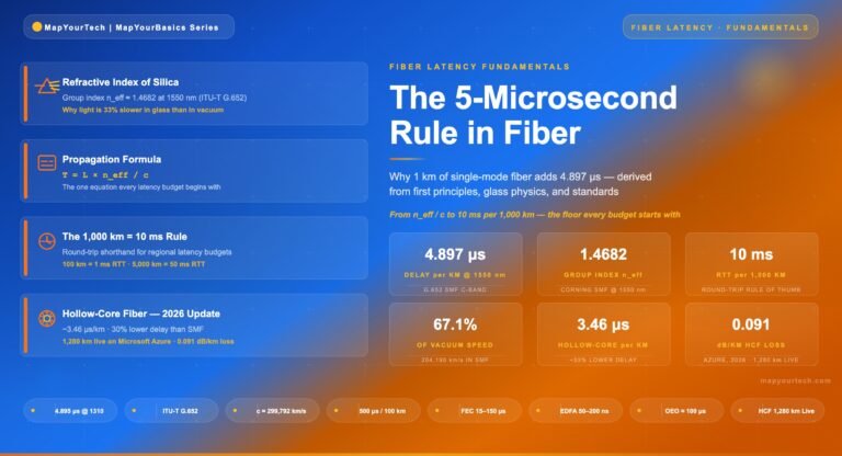
The 5-Microsecond Rule: Fiber Propagation Latency Fiber Latency Fundamentals · MapYourTech The 5-Microsecond Rule: Fiber Propagation Latency per Kilometer How...
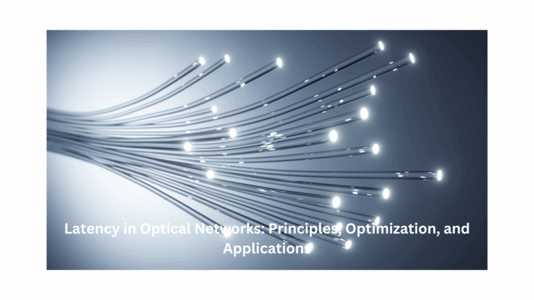
Latency in Coherent Optical Systems MapYourTech · InDepth Series Latency in Coherent Optical Systems A comprehensive technical analysis of propagation...