
Latency in Fiber Optic Networks
As we are very much aware that Internet traffic is growing very fast. The more information we are transmitting the more we need to think about parameters like available bandwidth and latency. Bandwidth is usually understood by end-users as the important indicator and measure of network performance. It is surely a reliable figure of merit, but it mainly depends on the characteristics of the equipment. Unlike bandwidth, latency and jitter depend on the specific context of transmission network topology and traffic conditions.
Latency we understand delay from the time of packet transmission at the sender to the end of packet reception at the receiver. If latency is too high it spreads data packets over the time and can create an impression that an optical metro network is not operating at data transmission speed which was expected. Data packets are still being transported at the same bit rate but due to latency they are delayed and affect the overall transmission system performance.
It should be pointed out, that there is need for low latency optical networks in almost all industries where any data transmission is realized. It is becoming a critical requirement for a wide set of applications like financial transactions, videoconferencing, gaming, telemedicine and cloud services which requires transmission line with almost no delay performance. These industries are summarized and shown in table below, please see Table 1.
Table 1. Industries where low latency services are very important .

In fiber optical networks latency consists of three main components which adds extra time delay:
- the optical fiber itself,
- optical components
- opto-electrical components.
Therefore, for the service provider it is extremely important to choose best network components and think on efficient low latency transport strategy.
Latency is a critical requirement for a wide set of applications mentioned above. Even latency of 250 ns can make the difference between winning and losing a trade. Latency reduction is very important in financial sector, for example, in the stock exchange market where 10 ms of latency could potentially result in a 10% drop in revenues for a company. No matter how fast you can execute a trade command, if your market data is delayed relative to competing traders, you will not achieve the expected fill rates and your revenue will drop. Low latency trading has moved from executing a transaction within several seconds to milliseconds, microseconds, and now even to nanoseconds.
LATENCY SOURCES IN OPTICAL NETWORKS
Latency is a time delay experienced in system and it describes how long it takes for data to get from transmission side to receiver side. In a fiber optical communication systems it is essentially the length of optical fiber divided by the speed of light in fiber core, supplemented with delay induced by optical and electro optical elements plus any extra processing time required by system, also called overhead.Signal processing delay can be reduced by using parallel processing based on large scale integration CMOS technologies.
Added to the latency due to propagation in the fiber, there are other path building blocks that affect the total data transport time. These elements include
- opto-electrical conversion,
- switching and routing,
- signal regeneration,
- amplification,
- chromatic dispersion (CD) compensation,
- polarization mode dispersion (PMD) compensation,
- data packing, digital signal processing (DSP),
- protocols and addition forward error correction (FEC)
Data transmission speed over optical metro network must be carefully chosen. If we upgrade 2.5 Gbit/s link to 10 Gbit/s link then CD compensation or amplification may be necessary, but it also will increase overall latency. For optical lines with transmission speed more than 10 Gbit/s (e.g. 40 Gbit/s) a need for coherent detection arises. In coherent detection systems CD can be electrically compensated using DSP which also adds latency. Therefore, some companies avoid using coherent detection for their low-latency network solutions.
From the standpoint of personal communications, effective dialogue requires latency < 200 ms, an echo needs > 80 ms to be distinguished from its source, remote music lessons require latency < 20 ms, and remote performance < 5 ms. It has been reported that in virtual environments, human beings can detect latencies as low as 10 to 20 ms. In trading industry or in telehealth every microsecond matters. But in all cases, the lower latency we can get the better system performance will be.
Single mode optical fiber
In standard single-mode fiber, a major part of light signal travels in the core while a small amount of light travels in the cladding. Optical fiber with lower group index of refraction provides an advantage in low latency applications.It is useful to use a parameter “effective group index of refraction (neff) instead of “index of refraction (n)” which only defines the refractive index of core or cladding of single mode fiber. The neff parameter is a weighted average of all the indices of refraction encountered by light as it travels within the fiber, and therefore it represents the actual behavior of light within a given fiber.The impact of profile shape on neff by comparing its values for several Corning single mode fiber (SMF) products with different refractive index profiles is illustrated in Fig. 2.
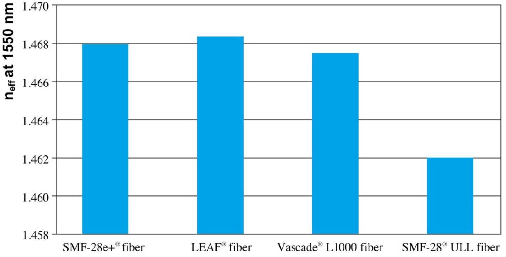
Figure 2. Effective group index of refraction impact of various commercially available Corning single mode fiber types.
It is known that speed of light in vacuum is 299792.458 km/s. Assuming ideal propagation at the speed of light in vacuum, an unavoidable latency value can be calculated as following in Equation (1):
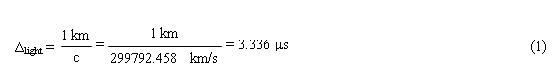
However, due to the fiber’s refractive index light travels more slowly in optical fiber than in vacuum. In standard single mode fiber defined by ITU-T G.652 recommendation the effective group index of refraction (neff), for example, can be equal to 1.4676 for transmission on 1310 nm and 1.4682 for transmission on 1550 nm wavelength. By knowing neff we can express the speed of light in selected optical fiber at 1310 and 1550 nm wavelengths, see Equations (2) and (3):

By knowing speed of light in optical fiber at different wavelengths (see Equation (2) and (3) ) optical delay which is caused by 1 km long optical fiber can be calculated as following:

As one can see from Equations (4) and (5), propagation delay of optical signal is affected not only by the fiber type with certain neff, but also with the wavelength which is used for data transmission over fiber optical network. It is seen that optical signal delay values in single mode optical fiber is about 4.9 μs. This value is the practically lower limit of latency achievable for 1 km of fiber in length if it were possible to remove all other sources of latency caused by other elements and data processing overhead.
Photonic crystal fibers (PCFs) can have very low effective refractive index, and can propagate light much faster than in SMFs. For example, hollow core fiber (HCF) may provide up to 31% reduced latency relative to traditional fiber optics. But there is a problem that attenuation in HCF fibers is much higher compared to already implemented standard single mode fibers (for SMF α=0.2 dB/km but for HCF α=3.3 dB/km at 1550 nm). However, it is reported even 1.2 dB/km attenuation obtained in hollow-core photonic crystal fiber.
Chromatic Dispersion Compensation
Chromatic dispersion (CD) occurs because different wavelengths of light travel at different speeds in optical fiber. CD can be compensated by dispersion compensation module (DCM) where dispersion compensating fiber (DCF) or fiber Bragg grating (FBG) is employed.
A typical long reach metro access fiber optical network will require DCF approximately 15 to 25% of the overall fiber length. It means that use of DCF fiber adds about 15 to 25% to the latency of the fiber.For example, 100 km long optical metro network where standard single mode fiber (SMF) is used, can accumulate chromatic dispersion in value about 1800 ps/nm at 1550 nm wavelength.For full CD compensation is needed about 22.5 km long DCF fiber spool with large negative dispersion value (typical value is -80 ps/nm/km).If we assume that light propagation speed in DCF fiber is close to speed in SMF then total latency of 100 km long optical metro network with CD compensation using DCF DCM is about 0.6 ms.
Solution for how to avoid need for chromatic dispersion compensation or reduce the length of necessary DCF fiber is to use optical fiber with lower CD coefficient. For example, non-zero dispersion shifted fibers (NZ-DSFs) were developed to simplify CD compensation while making a wide band of channels available. NZ-DSF fiber parameters are defined in ITU-T G.655 recommendation. Today NZ-DSF fibers are optimized for regional and metropolitan high speed optical networks operating in the C- and L- optical bands. For C band it is defined that wavelength range is from 1530 to 1565 nm, but for L band it is from 1565 to 1625 nm.
For commercially available NZ-DSF fiber chromatic dispersion coefficient can be from 2.6 to 6.0 ps/nm/km in C-band and from 4.0 to 8.9 ps/nm/km in L-band. At 1550 nm region typical CD coefficient is about 4 ps/nm/km for this type of fiber. It can be seen that for G.655 NZ-DSF fiber CD coefficient is about four times lower than for standard G.652 SMF fiber.Since these fibers have lower dispersion than conventional single mode, simpler modules are used that add only up to 5% to the transmission time for NZ-DSF.7 This enables a lower latency than using SMF fiber for transmission. Another solution how to minimize need for extra CD compensation or reduce it to the necessary minimum is dispersion shifted fiber (DSF) which is specified in ITU-T G.653 recommendation. This fiber is optimized for use in 1550 nm region and has no chromatic dispersion at 1550 nm wavelength. Although, it is limited to single-wavelength operation due to non-linear four wave mixing (FWM), which causes optical signal distortions.
If CD is unavoidable another technology for compensation of accumulated CD is a deployment of fiber Bragg gratings (FBG). DCM with FBG can compensate several hundred kilometers of CD without any significant latency penalty and effectively remove all the additional latency that DCF-based networks add.In other words, a lot of valuable microseconds can be gained by migrating from DCF DCM to FBG DCM technology in optical metro network.Typical fiber length in an FBG used for dispersion compensation is about 10 cm. Therefore, normally FBG based DCM can introduce from 5 to 50 ns delay in fiber optical transmission line.
One of solutions how to avoid implementation of DCF DCM which introduces addition delay is coherent detection where complex transmission formats such as quadrature phase-shift keying (QPSK) can be used. However, it must be noticed that it can be a poor choice from a latency perspective because of the added digital signal processing (DSP) time it require. This additional introduced delay can be up to 1 μs.
Optical amplifiers
Another key optical component which adds additional time delay to optical transmission line is optical amplifier. Erbium doped fiber amplifiers (EDFA) is widely used in fiber optical access and long haul networks. EDFA can amplify signals over a band of almost 30 to 35 nm extending from 1530 to1565 nm, which is known as the C-band fiber amplifier, and from 1565 to 1605 nm, which is known as the L-band EDFA.The great advantage of EDFAs is that they are capable of amplifying many WDM channels simultaneously and there is no need to amplify each individual channel separately. EDFAs also remove the requirement for optical-electrical-optical (OEO) conversion, which is highly beneficial from a low-latency perspective. However it must be taken into account that EDFA contains few meters of erbium-doped optical fiber (Er3+) which adds extra latency, although this latency amount is small compared with other latency contributors. Typical EDFA amplifier contains up to 30 m long erbium doped fiber. These 30 m of additional fiber add 147 ns (about 0.15 μs) time delay.
Solution to how to avoid or reduce extra latency if amplification is necessary is use of Raman amplifier instead of EDFA or together (in tandem) with EDFA. This combination provides maximal signal amplification with minimal latency. Raman amplifiers use a different optical characteristic to amplify the optical signal.Raman amplification is realized by using stimulated Raman scattering. The Raman gain spectrum is rather broad, and the peak of the gain is centered about 13 THz (100 nm in wavelength) below the frequency of the pump signal used. Pumping a fiber using a high-power pump laser, we can provide gain to other signals, with a peak gain obtained 13 THz below the pump frequency. For example, using pumps around 1460–1480 nm wavelength provides Raman gain in the 1550–1600 nm window, which partly cover C and L bands. Accordingly, we can use the Raman effect to provide gain at any wavelength we want to amplify. The main benefit regarding to latency is that Raman amplifier pump optical signal without adding fiber to the signal path, therefore we can assume that Raman amplifier adds no latency.
Transponders and opto-electrical conversion
Any transmission line components which are performing opto-electrical conversion increase total latency. One of key elements used in opto-electrical conversion are transponders and muxponders. Transponders convert incoming signal from the client to a signal suitable for transmission over the WDM link and an incoming signal from the WDM link to a suitable signal toward the client.Muxponder basically do the same as transponder except that it has additional option to multiplex lower rate signals into a higher rate carrier (e.g. 10 Gbit/s services up to 40 Gbit/s transport) within the system in such a way saving valuable wavelengths in the optical metro network.
The latency of both transponders and muxponders varies depending on design, functionality, and other parameters. Muxponders typically operate in the 5 to 10 μs range per unit. The more complex transponders include additional functionality such as in-band management channels. This complexity forces the unit design and latency to be very similar to a muxponder, in the 5 to 10 μs range. If additional FEC is used in these elements then latency value can be higher.Several telecommunications equipment vendors offer simpler and lower-cost transponders that do not have FEC or in-band management channels or these options are improved in a way to lower device delay. These modules can operate at much lower latencies, from 4 ns to 30 ns. Some vendors also claim that their transponders operate with 2 ns latency which is equivalent to adding about a half meter of SMF to fiber optical path.
Optical signal regeneration
For low latency optical metro networks it is very important to avoid any regeneration and focus on keeping the signal in the optical domain once it is entered the fiber. An optical-electronic-optical (OEO) conversion takes about 100 μs, depending on how much processing is required in the electrical domain. Ideally a carrier would like to avoid use of FEC or full 3R (reamplification, reshaping, retiming) regeneration. 3R regeneration needs OEO conversion which adds unnecessary time delay. Need for optical signal regeneration is determined by transmission data rate involved, whether dispersion compensation or amplification is required, and how many nodes the signal must pass through along the fiber optical path.
Forward error correction and digital signal processing
It is necessary to minimize the amount of electrical processing at both ends of fiber optical connection. FEC, if used (for example, in transponders) will increase the latency due to the extra processing time. This approximate latency value can be from 15 to 150 μs based on the algorithm used, the amount of overhead, coding gain, processing time and other parameters.
Digital signal processing (DSP) can be used to deal with chromatic dispersion (CD), polarization mode dispersion (PMD) and remove critical optical impairments. But it must be taken into account that DSP adds extra latency to the path. It has been mentioned before that this additional introduced delay can be up to 1 μs.
Latency regarding OSI Levels
Latency is not added only by the physical medium but also because of data processing implemented in electronic part of fiber optical metro network (basically transmitter and receiver). All modern networks are based upon the Open System Interconnection (OSI) reference model which consists of a 7 layer protocol stack, see Fig. 3.

Figure 3. OSI reference model illustrating (a) total latency increase over each layer and (b) data way passing through all protocol layers in transmitter and receiver.
SUMMARY
Latency sources in optical metro network and typical induced time delay values.


