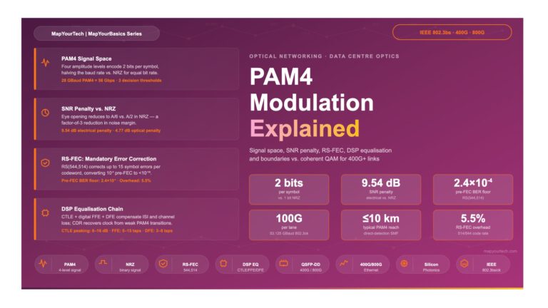
Tag

Forward Error Correction

Browsing

In this ever-evolving landscape of optical networking, the development of coherent optical standards, such as 400G ZR and ZR+, represents a significant leap forward in addressing the insatiable demand for bandwidth, efficiency, and scalability in data centers and network infrastructure. This technical blog delves into the nuances of these standards, comparing their features, applications, and how they are shaping the future of high-capacity networking.

Introduction to 400G ZR

The 400G ZR standard, defined by the Optical Internetworking Forum (OIF), is a pivotal development in the realm of optical networking, setting the stage for the next generation of data transmission over optical fiber’s. It is designed to facilitate the transfer of 400 Gigabit Ethernet over single-mode fiber across distances of up to 120 kilometers without the need for signal amplification or regeneration. This is achieved through the use of advanced modulation techniques like DP-16QAM and state-of-the-art forward error correction (FEC).

Key features of 400G ZR include:

  • High Capacity: Supports the transmission of 400 Gbps using a single wavelength.
  • Compact Form-Factor: Integrates into QSFP-DD and OSFP modules, aligning with industry standards for data center equipment.
  • Cost Efficiency: Reduces the need for external transponders and simplifies network architecture, lowering both CAPEX and OPEX.

Emergence of 400G ZR+

Building upon the foundation set by 400G ZR, the 400G ZR+ standard extends the capabilities of its predecessor by increasing the transmission reach and introducing flexibility in modulation schemes to cater to a broader range of network topologies and distances. The OpenZR+ MSA has been instrumental in this expansion, promoting interoperability and open standards in coherent optics.

Key enhancements in 400G ZR+ include:

  • Extended Reach: With advanced FEC and modulation, ZR+ can support links up to 2,000 km, making it suitable for longer metro, regional, and even long-haul deployments.
  • Versatile Modulation: Offers multiple configuration options (e.g., DP-16QAM, DP-8QAM, DP-QPSK), enabling operators to balance speed, reach, and optical performance.
  • Improved Power Efficiency: Despite its extended capabilities, ZR+ maintains a focus on energy efficiency, crucial for reducing the environmental impact of expanding network infrastructures.

ZR vs. ZR+: A Comparative Analysis

Feature. 400G ZR 400G ZR+
Reach Up to 120 km Up to 2,000 km
Modulation DP-16QAM DP-16QAM, DP-8QAM, DP-QPSK
Form Factor QSFP-DD, OSFP QSFP-DD, OSFP
Application Data center interconnects Metro, regional, long-haul

Adding few more interesting table for readersZR

The Future Outlook

The advent of 400G ZR and ZR+ is not just a technical upgrade; it’s a paradigm shift in how we approach optical networking. With these technologies, network operators can now deploy more flexible, efficient, and scalable networks, ready to meet the future demands of data transmission.

Moreover, the ongoing development and expected introduction of XR optics highlight the industry’s commitment to pushing the boundaries of what’s possible in optical networking. XR optics, with its promise of multipoint capabilities and aggregation of lower-speed interfaces, signifies the next frontier in coherent optical technology.

In the pursuit of ever-greater data transmission capabilities, forward error correction (FEC) has emerged as a pivotal technology, not just in wireless communication but increasingly in large-capacity, long-haul optical systems. This blog post delves into the intricacies of FEC and its profound impact on the efficiency and cost-effectiveness of modern optical networks.

The Introduction of FEC in Optical Communications

FEC’s principle is simple yet powerful: by encoding the original digital signal with additional redundant bits, it can correct errors that occur during transmission. This technique enables optical transmission systems to tolerate much higher bit error ratios (BERs) than the traditional threshold of 10−1210−12 before decoding. Such resilience is revolutionizing system design, allowing the relaxation of optical parameters and fostering the development of vast, robust networks.

Defining FEC: A Glossary of Terms

inband_outband_fec

Understanding FEC starts with grasping its key terminology. Here’s a brief rundown:

  • Information bit (byte): The original digital signal that will be encoded using FEC before transmission.
  • FEC parity bit (byte): Redundant data added to the original signal for error correction purposes.
  • Code word: A combination of information and FEC parity bits.
  • Code rate (R): The ratio of the original bit rate to the bit rate with FEC—indicative of the amount of redundancy added.
  • Coding gain: The improvement in signal quality as a result of FEC, quantified by a reduction in Q values for a specified BER.
  • Net coding gain (NCG): Coding gain adjusted for noise increase due to the additional bandwidth needed for FEC bits.

The Role of FEC in Optical Networks

The application of FEC allows for systems to operate with a BER that would have been unacceptable in the past, particularly in high-capacity, long-haul systems where the cumulative noise can significantly degrade signal quality. With FEC, these systems can achieve reliable performance even with the presence of amplified spontaneous emission (ASE) noise and other signal impairments.

In-Band vs. Out-of-Band FEC

There are two primary FEC schemes used in optical transmission: in-band and out-of-band FEC. In-band FEC, used in Synchronous Digital Hierarchy (SDH) systems, embeds FEC parity bits within the unused section overhead of SDH signals, thus not increasing the bit rate. In contrast, out-of-band FEC, as utilized in Optical Transport Networks (OTNs) and originally recommended for submarine systems, increases the line rate to accommodate FEC bits. ITU-T G.709 also introduces non-standard out-of-band FEC options optimized for higher efficiency.

Achieving Robustness Through FEC

The FEC schemes allow the correction of multiple bit errors, enhancing the robustness of the system. For example, a triple error-correcting binary BCH code can correct up to three bit errors in a 4359 bit code word, while an RS(255,239) code can correct up to eight byte errors per code word.

fec_performance

Performance of standard FECs

The Practical Impact of FEC

Implementing FEC leads to more forgiving system designs, where the requirement for pristine optical parameters is lessened. This, in turn, translates to reduced costs and complexity in constructing large-scale optical networks. The coding gains provided by FEC, especially when considered in terms of net coding gain, enable systems to better estimate and manage the OSNR, crucial for maintaining high-quality signal transmission.

Future Directions

While FEC has proven effective in OSNR-limited and dispersion-limited systems, its efficacy against phenomena like polarization mode dispersion (PMD) remains a topic for further research. Additionally, the interplay of FEC with non-linear effects in optical fibers, such as self-phase modulation and cross-phase modulation, presents a rich area for ongoing study.

Conclusion

FEC stands as a testament to the innovative spirit driving optical communications forward. By enabling systems to operate with higher BERs pre-decoding, FEC opens the door to more cost-effective, expansive, and resilient optical networks. As we look to the future, the continued evolution of FEC promises to underpin the next generation of optical transmission systems, making the dream of a hyper-connected world a reality.

References

https://www.itu.int/rec/T-REC-G/e

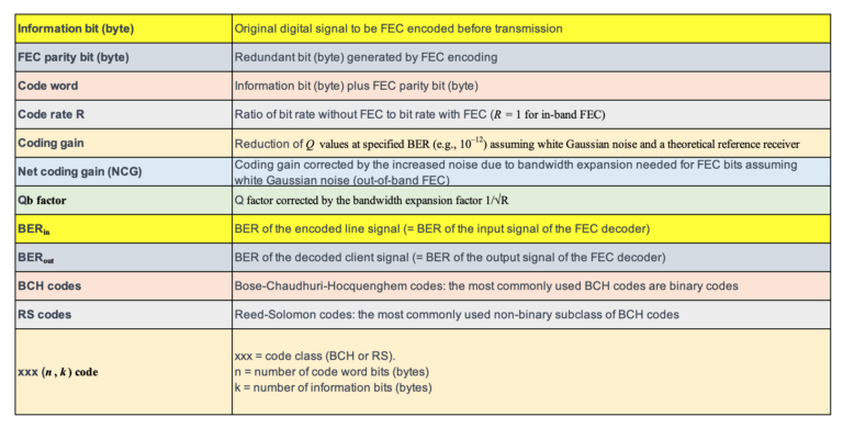
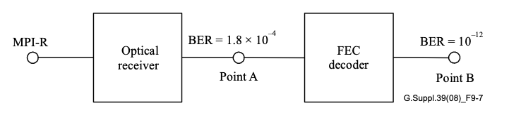
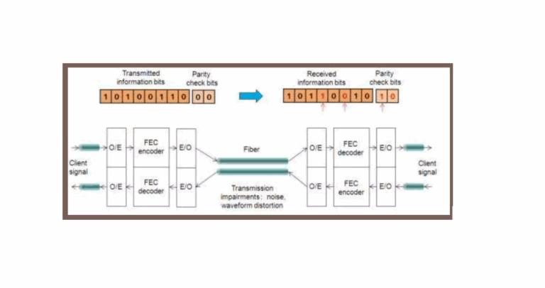
Forward Error Correction (FEC) has become an indispensable tool in modern optical communication, enhancing signal integrity and extending transmission distances. ITU-T recommendations, such as G.693, G.959.1, and G.698.1, define application codes for optical interfaces that incorporate FEC as specified in ITU-T G.709. In this blog, we discuss the significance of Bit Error Ratio (BER) in FEC-enabled applications and how it influences optical transmitter and receiver performance.

The Basics of FEC in Optical Communications

FEC is a method of error control for data transmission, where the sender adds redundant data to its messages. This allows the receiver to detect and correct errors without the need for retransmission. In the context of optical networks, FEC is particularly valuable because it can significantly lower the BER after decoding, thus ensuring the accuracy and reliability of data across vast distances.

BER Requirements in FEC-Enabled Applications

For certain optical transport unit rates (OTUk), the system BER is mandated to meet specific standards only after FEC correction has been applied. The optical parameters, in these scenarios, are designed to achieve a BER no worse than 10−12 at the FEC decoder’s output. This benchmark ensures that the data, once processed by the FEC decoder, maintains an extremely high level of accuracy, which is crucial for high-performance networks.

Practical Implications for Network Hardware

When it comes to testing and verifying the performance of optical hardware components intended for FEC-enabled applications, achieving a BER of 10−12 at the decoder’s output is often sufficient. Attempting to test components at 10−12 at the receiver output, prior to FEC decoding, can lead to unnecessarily stringent criteria that may not reflect the operational requirements of the application.

Adopting Appropriate BER Values for Testing

The selection of an appropriate BER for testing components depends on the specific application. Theoretical calculations suggest a BER of 1.8×10⁻⁴at the receiver output (Point A) to achieve a BER of 10−12 at the FEC decoder output (Point B). However, due to variations in error statistics, the average BER at Point A may need to be lower than the theoretical value to ensure the desired BER at Point B. In practice, a BER range of 10−5 to 10−6 is considered suitable for most applications.

Conservative Estimation for Receiver Sensitivity

By using a BER of 10−6 for component verification, the measurements of receiver sensitivity and optical path penalty at Point A will be conservative estimates of the values after FEC correction. This approach provides a practical and cost-effective method for ensuring component performance aligns with the rigorous demands of FEC-enabled systems.

Conclusion

FEC is a powerful mechanism that significantly improves the error tolerance of optical communication systems. By understanding and implementing appropriate BER testing methodologies, network operators can ensure their components are up to the task, ultimately leading to more reliable and efficient networks.

As the demands for data grow, the reliance on sophisticated FEC techniques will only increase, cementing BER as a fundamental metric in the design and evaluation of optical communication systems.

References

https://www.itu.int/rec/T-REC-G/e

Items HD-FEC SD-FEC
Definition Decoding based on hard-bits(the output is quantized only to two levels) is called the “HD(hard-decision) decoding”, where each bit is considered definitely one or zero. Decoding based on soft-bits(the output is quantized to more than two levels) is called the “SD(soft-decision) decoding”, where not only one or zero decision but also confidence information for the decision are provided.
Application Generally for non-coherent detection optical systems, e.g.,  10 Gbit/s, 40 Gbit/s, also for some coherent detection optical systems with higher OSNR coherent detection optical systems, e.g.,  100 Gbit/s,400 Gbit/s.
Electronics Requirement ADC(Analogue-to-Digital Converter) is not necessary in the receiver. ADC is required in the receiver to provide soft information, e.g.,  coherent detection optical systems.
specification general FEC per [ITU-T G.975];super FEC per [ITU-T G.975.1]. vendor specific
typical scheme Concatenated RS/BCH LDPC(Low density parity check),TPC(Turbo product code)
complexity medium high
redundancy ratio generally 7% around 20%
NCG about 5.6 dB for general FEC;>8.0 dB for super FEC. >10.0 dB
 Example(If you asked your friend about traffic jam status on roads and he replies) maybe fully jammed or free  50-50  but I found othe way free or less traffic

FEC codes in optical communications are based on a class of codes know as Reed-Solomon.

Reed-Solomon code is specified as  RS (nk), which means that the encoder takes k data bytes and adds parity bytes to make an n bytes codeword. A Reed-Solomon decoder can correct up to t bytes in the codeword, where 2t=n – k.


ITU recommendation G.975 proposes a Reed-Solomon (255, 239). In this case 16 extra bytes are appended to 239 information-bearing bytes. The bit rate increase is about 7% [(255-239)/239 = 0.066], the code can correct up to 8 byte errors [255-239/2 =8] and the coding gain can be demonstrated to be about 6dB.

The same Reed-Solomon coding (RS (255,239)) is recommended in ITU-T G.709. The coding overhead is again about 7% for a 6dB coding gain. Both G.975 and G.709 improve the efficiency of the Reed-Solomon by interleaving data from different codewords. The interleaving technique carries an advantage for burst errors, because the errors can be shared across many different codewords. In the interleaving approach lies the main difference between G.709 and G.975: G.709 interleave approach is fully standardized,while G.975 is not.

The actual G.975 data overhead includes also one bit for framing overhead, therefore the bit rate exp ansion is [(255-238)/238 = 0.071]. In G.709 the frame overhead is higher than in G.975, hence an even higher bit rate expansion. One byte error occurs when 1 bit in a byte is wrong or when all the bits in a byte are wrong. Example: RS (255,239) can correct 8 byte errors. In the worst case, 8 bit errors may occur, each in a separate byte so that the decoder corrects 8 bit errors. In the best case, 8 complete byte errors occur so that the decoder corrects 8 x 8 bit errors.

There are other, more powerful and complex RS variants (like for example concatenating two RS codes) capable of Coding Gain 2 or 3 dB higher than the ITU-T FEC codes, but at the expense of an increased bit rate (sometimes as much as 25%).

FOR OTN FRAME: Calculation of RS( n,k) is as follows:-

*OPU1 payload rate= 2.488 Gbps (OC48/STM16)


*Add OPU1 and ODU1 16 bytes overhead:


3808/16 = 238, (3808+16)/16 = 239

ODU1 rate: 2.488 x 239/238** ~ 2.499Gbps

*Add FEC

OTU1 rate: ODU1 x 255/239 = 2.488 x 239/238 x 255/239

=2.488 x 255/238 ~2.667Gbps


NOTE:4080/16=(255)

**Multiplicative factor is just a simple math :eg. for ODU1/OPU1=3824/3808={(239*16)/(238*16)}

Here value of multiplication factor will give the number of times  for rise in the frame size after adding header/overhead.

As we are using Reed Soloman(255,239) i.e we are dividing 4080bytes in sixteen frames (The forward error correction for the OTU-k uses 16-byte interleaved codecs using a Reed- Solomon S(255,239) code. The RS(255,239) code operates on byte symbols.).

Hence 4080/16=255…I have understood it you need to do simpler maths to understand..)