
Optical Transport Network (OTN)
| ITU-T Recommendations on the OTN Transport Plane | ||||||||||||||||||||||||||||||||||||||||||||||||||||||||||||||||||||||||||||||||||||||||||||||||||||||||||||||||||||||||
|
COMPARISON OF SDH AND OTN


3 Optical transport network interface structure
3.1.2 Full functionality OTM-n.m (n ≥ 1) structure
3.1.3 Reduced functionality OTM-nr.m and OTM-0.m structure
3.2 Information structure for the OTN interfaces
4 Multiplexing/mapping principles and bit rates
4.2 Wavelength division multiplex
4.4 ODUk Time-Division Multiplex
5 OTUk, ODUk, OPUk Frame Structure
5.1 OPUk Overhead and Processing
5.1.1 Payload Structure Identifier (PSI)
5.2 ODUk Overhead and Processing
5.2.2 Tandem Connection Monitoring (TCM)
5.2.3 General Communication Channels (GCC1, GCC2)
5.2.4 Automatic Protection Switching and Protection Communication Channel (APS/PCC)
5.2.5 Fault Type and Fault Location reporting communication channel (FTFL)
5.3 OTUk Overhead and Processing
5.3.2 Frame Alignment Overhead
5.3.4 General Communication Channel 0 (GCC0)
6.1.1 OTUk alarm indication signal (OTUk-AIS)
6.2.1 ODUk Open Connection Indication (ODUk-OCI)
6.2.3 ODUk Alarm Indication Signal (ODUk-AIS)
6.3.1 Generic AIS for constant bit rate signals
7.1 Default PLM (Payload Mismatch)
7.2 Default MSIM (Multiplex Structure Identifier Mismatch supervision)
7.3 Default LOFLOM (Loss of Frame and Multi-frame)
9.1 Forward Error Correction (FEC)
9.2 Tandem Connection Monitoring
9.3 Transparent Transport of Client Signals
1 Abbreviations
This document uses the following abbreviations:
0xYY YY is a value in hexadecimal presentation
3R Re-amplification, Reshaping and Retiming
ACT Activation (in the TCM ACT byte)
AI Adapted Information
AIS Alarm Indication Signal
APS Automatic Protection Switching
BDI Backward Defect Indication
BEI Backward Error Indication
BIAE Backward Incoming Alignment Error
BIP Bit Interleaved Parity
CBR Constant Bit Rate
CI Characteristic Information
CM Connection Monitoring
CRC Cyclic Redundancy Check
DAPI Destination Access Point Identifier
EXP Experimental
ExTI Expected Trace Identifier
FAS Frame Alignment Signal
FDI Forward Defect Indication
FEC Forward Error Correction
GCC General Communication Channel
IaDI Intra-Domain Interface
IAE Incoming Alignment Error
IrDI Inter-Domain Interface
JOH Justification Overhead
LSB Least Significant Bit
MFAS Multi-Frame Alignment Signal
MFI Multi-frame Indicator
MS Maintenance Signal
MSB Most Significant Bit
MSI Multiplex Structure Identifier
NNI Network Node Interface
OCh Optical channel with full functionality
OCI Open Connection Indication
ODU Optical Channel Data Unit
ODUk Optical Channel Data Unit-k
ODTUjk Optical channel Data Tributary Unit j into k
ODTUG Optical channel Data Tributary Unit Group
ODUk-Xv X virtually concatenated ODUk’s
OH Overhead
OMS Optical Multiplex Section
OMS-OH Optical Multiplex Section Overhead
OMU Optical Multiplex Unit
ONNI Optical Network Node Interface
OOS OTM Overhead Signal
OPS Optical Physical Section
OPU Optical Channel Payload Unit
OPUk Optical Channel Payload Unit-k
OPUk-Xv X virtually concatenated OPUk’s
OSC Optical Supervisory Channel
OTH Optical Transport Hierarchy
OTM Optical Transport Module
OTN Optical Transport Network
OTS Optical Transmission Section
OTS -OH Optical Transmission Section Overhead
OUT Optical Channel Transport Unit
OTUk Optical Channel Transport Unit-k
PCC Protection Communication Channel
PM Path Monitoring
PMI Payload Missing Indication
PMOH Path Monitoring OverHead
Ppm parts per million
PRBS Pseudo Random Binary Sequence
PSI Payload Structure Identifier
PT Payload Type
RES Reserved for future international standardization
RS Reed-Solomon
SAPI Source Access Point Identifier
Sk Sink
SM Section Monitoring
SMOH Section Monitoring OverHead
So Source
TC Tandem Connection
TCM Tandem Connection Monitoring
TS Tributary Slot
TxTI Transmitted Trace Identifier
UNI User-to-Network Interface
VCG Virtual Concatenation Group
VCOH Virtual Concatenation Overhead
vcPT virtual concatenated Payload Type
2 What is OTN/OTH
The Optical Transport Hierarchy (OTH) is a new transport technology for the OTN developed by the ITU. It is based on the network architecture defined in ITU G.872 “Architecture for the Optical Transport Network (OTN)”.
G.872 defines an architecture that is composed of the Optical Channel (OCh), Optical Multiplex Section (OMS) and Optical Transmission Section (OTS). It then describes the functionality that is needed to make OTN work. However, it may be interesting to note the decision made during G.872 development:
“During the development of ITU-T Rec. G.709, (implementation of the Optical Channel Layer according to ITU-T Rec. G.872 requirements), it was realized that the only techniques presently available that could meet the requirements for associated OCh trace, as well as providing an accurate assessment of the quality of a digital client signal, were digital techniques….”
“For this reason ITU-T Rec. G.709 chose to implement the Optical Channel by means of a digital framed signal with digital overhead that supports the management requirements for the OCh. Furthermore this allows the use of Forward Error Correction for enhanced system performance. This results in the introduction of two digital layer networks, the ODU and OTU. The intention is that all client signals would be mapped into the Optical Channel via the ODU and OTU layer networks.”
Currently there are no physical implementations of the OCh, OMS and OTS layers. As they are defined and implemented, they will be included in this document.
2.1 References
ITU-T Rec. G.709 (2009) “Interfaces for the Optical Transport Network (OTN)”
ITU-T Rec. G.798 (2010) “Characteristics of optical transport network hierarchy equipment functional blocks”
ITU-T Rec. G.872 (2001) “Architecture of optical transport networks”
ITU-T Rec. G.873.1 (2006) “Optical Transport Network: Linear protection”
ITU-T Rec. G.874 (2010) “Management aspects of the optical transport network element”
ITU-T Rec. G.874.1 (2002) “Optical transport network: Protocol-neutral management information model for the network element view”
ITU-T Rec. G.959.1 (2009) “Optical transport network physical layer interfaces”
ITU-T Rec. G.8251 (2011) “The control of jitter and wander within the optical transport network (OTN)”

3 Optical transport network interface structure
3.1 Basic signal structure
Figure 1 Structure of the OTN interfaces
3.1.1 OCh substructure
The optical channel layer is further structured in layer networks in order to support the network management and supervision functionalities:
- The optical channel with full (OCh) or reduced functionality (OChr), which provides transparent network connections between 3R regeneration points in the OTN.
- The optical channel transport unit (OTUk/OTUkV) which provides supervision and conditions the signal for transport between 3R regeneration points in the OTN.
- The optical channel data unit (ODUk) which provides:
- tandem connection monitoring (ODUkT)
- end-to-end path supervision (ODUkP)
- adaptation of client signals via the optical channel payload unit (OPUk)
- adaptation of OTN ODUk signals via the optical channel payload unit (OPUk)
3.1.2 Full functionality OTM-n.m (n ≥ 1) structure
The OTM-n.m (n ≥ 1) consists of the following layers:
- optical transmission section (OTSn)
- optical multiplex section (OMSn)
- optical channel (OCh)
- optical channel transport unit (OTUk/OTUkV)
- one or more optical channel data unit (ODUk)
3.1.3 Reduced functionality OTM-nr.m and OTM-0.m structure
The OTM-nr.m and OTM-0.m consist of the following layers:
- optical physical section (OPSn)
- reduced functionality optical channel (OChr)
- optical channel transport unit (OTUk/OTUkV)
- one or more optical channel data unit (ODUk)

3.2 Information structure for the OTN interfaces
Figure 2 Principal information containment relationships
The following layers are defined in OTN:
- OPUk: Optical channel payload unit k (k = 0, 1, 2, 3, 4)
- ODUk: Optical channel data unit k (k = 0, 1, 2, 3, 4)
- OTUk: Optical channel transport unit k (k = 1, 2, 3, 4)
- OCh: Optical channel, a single wavelength
- OMSn: Optical multiplex section of order n (Capacities for n = 0 and n = 16 are defined)
- OTSn: Optical transmission section of order n (Capacities for n = 0 and n = 16 are defined)
- OTM-n.m: Optical transport module of rate m with n optical channels. Possible values for m are:
1: 2.5 Gb/s
2: 10 Gb/s
3: 40 Gb/s
4: 100 Gb/s
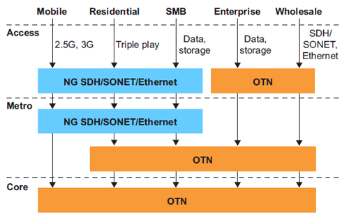
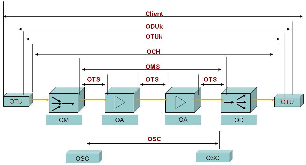
Figure 3 shows how they are being used in a network.

Figure 3 OTN Network Layers

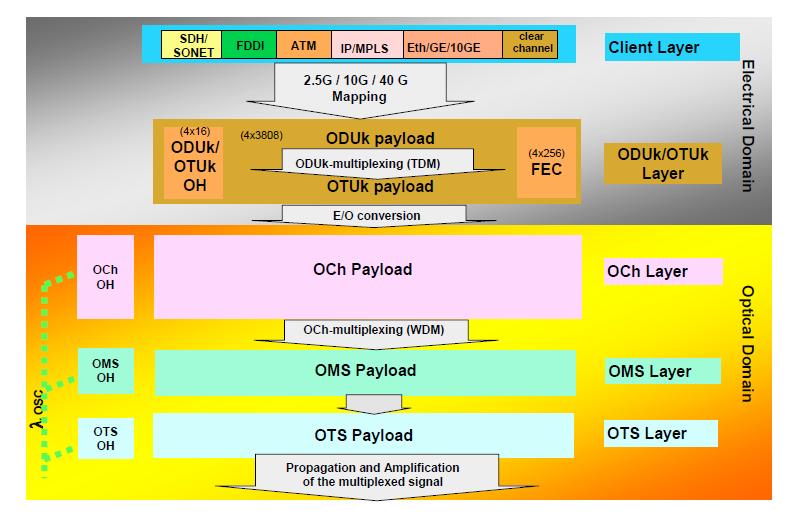
However for all intents and purposes there are only 4 layers
Figure 4 OTN Hierarchy
The OPUk, ODUk, and OTUk are in the electrical domain. The OCh is in the optical domain. There are more layers in the optical domain than just the OCh, but they are not being used now.
4 Multiplexing/mapping principles and bit rates
Figure 5 shows the relationship between various information structure elements and illustrates the multiplexing structure and mappings (including wavelength and time division multiplexing) for the OTM-n.

Figure 5 OTM multiplexing and mapping structure
The OTS, OMS, OCh and COMMS overhead is inserted into the OOS.
4.1 Mapping
The OPUk encapsulates the Client signal (e.g. SDH) and does any rate justification that is needed. It is analogous to the path layer in SDH in that it is mapped at the source, de-mapped at the sink, and not modified by the network.
The OPUk is mapped into an ODUk. The ODUk performs similar functions as the path overhead in SDH.
The ODUk is mapped into an OTUk[V]. The OTUk[V] contains the FEC and performs similar functions as the section overhead in SDH.
After the FEC are added, the signal is then sent to a serializer/ deserializer to be converted to the optical domain. The OTUk[V] is mapped into an OCh[r] and the OCh[r] is then modulated onto an OCC[r].
4.2 Wavelength division multiplex
Up to n (n ≥ 1) OCC[r] are multiplexed into an OCG-n[r].m using wavelength division multiplexing. The OCC[r] tributary slots of the OCG-n[r].m can be of different size.
The OCG-n[r].m is transported via the OTM-n[r].m. For the case of the full functionality OTM-n.m interfaces the OSC is multiplexed into the OTM-n.m using wavelength division multiplexing.
4.3 Bit rates and capacity
The data rates were constructed so that they could transfer SDH and Ethernet signals efficiently. The bit rates are shown in the following tables:

Table 1 OTU types and capacity

Table 2 ODU types and capacity

Table 3 OPU types and capacity
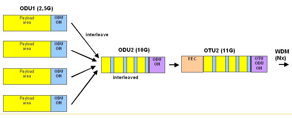
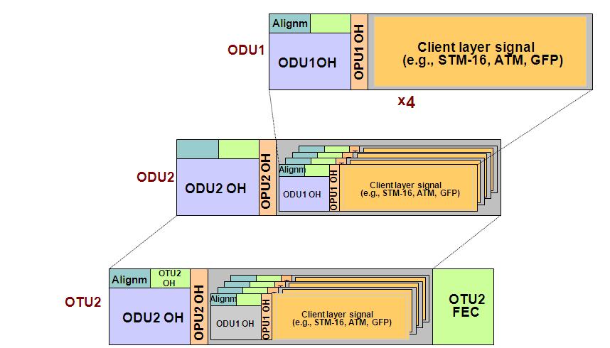
4.4 ODUk Time-Division Multiplex
Figure 6 and Figure 7 show the relationship between various information structure elements and illustrate the multiplexing structure and mappings (including wavelength and time division multiplexing) for the OTM-n. In the multi-domain OTN any combination of the ODUk multiplexing layers may be present at a given OTN interface.
Figure 6 shows that a (non-OTN) client signal is mapped into a lower order OPU, identified as “OPU (L)”. The OPU (L) signal is mapped into the associated lower order ODU, identified as “ODU (L)”. The ODU (L) signal is either mapped into the associated OTU[V] signal, or into an ODTU. The ODTU signal is multiplexed into an ODTU Group (ODTUG). The ODTUG signal is mapped into a higher order OPU, identified as “OPU (H)”. The OPU (H) signal is mapped into the associated higher order ODU, identified as “ODU (H)”. The ODU (H) signal is mapped into the associated OTU[V].
The OPU (L) and OPU (H) are the same information structures, but with different client signals. The concepts of lower order and high order ODU are specific to the role that ODU plays within a single domain.

Figure 6 OTM multiplexing and mapping structure
Figure 7 shows that an OTU[V] signal is mapped either into an optical channel signal, identified as OCh and OChr, or into an OTLk.n. The OCh/OChr signal is mapped into an optical channel carrier, identified as OCC and OCCr. The OCC/OCCr signal is multiplexed into an OCC group, identified as OCG-n.m and OCG-nr.m. The OCG-n.m signal is mapped into an OMSn. The OMSn signal is mapped into an OTSn. The OTSn signal is presented at the OTM-n.m interface.
The OCGnr.m signal is mapped into an OPSn. The OPSn signal is presented at the OTM-nr.m interface.
A single OCCr signal is mapped into an OPS0. The OPS0 signal is presented at the OTM-0.m interface. The OTLk.n signal is mapped into an optical transport lane carrier, identified as OTLC. The OTLC signal is multiplexed into an OTLC group, identified as OTLCG. The OTLCG signal is mapped into an OPSMnk. The OPSMnk signal is presented at the OTM-0.mvn interface.

Figure 7 OTM multiplexing and mapping structure
5 OTUk, ODUk, OPUk Frame Structure
Figure 8 shows the overall frame format for an OTUk signal. The various fields will be explained in the following sub-sections.

Figure 8 OTN frame format
5.1 OPUk Overhead and Processing
The OPUk (k = 1,2,3) frame structure is organized in an octet-based block frame structure with 4 rows and 3810 columns.

Figure 9 OPUk frame structure
The two main areas of the OPUk frame are:
- OPUk overhead area
- OPUk payload area
Columns 15 to 16 of the OPUk are dedicated to OPUk overhead area.
Columns 17 to 3824 of the OPUk are dedicated to OPUk payload area.
NOTE – OPUk column numbers are derived from the OPUk columns in the ODUk frame
OPUk OH information is added to the OPUk information payload to create an OPUk. It includes information to support the adaptation of client signals. The OPUk OH is terminated where the OPUk is assembled and disassembled.

Figure 10 OPUk frame
5.1.1 Payload Structure Identifier (PSI)
The 256-byte PSI signal is aligned with the ODUk multi-frame (i.e. PSI[0] is present at ODUk multi-frame position 0000 0000, PSI[1] at position 0000 0001, PSI[2] at position 0000 0010, etc.).
PSI[0] contains a one-byte payload type. PSI[1] to PSI[255] are mapping and concatenation specific.
5.1.2 Payload Type (PT)
A one-byte payload type signal is defined in the PSI[0] byte of the payload structure identifier to indicate the composition of the OPUk signal.
5.2 ODUk Overhead and Processing
The ODUk (k = 1,2,3) frame structure is organized in an octet-based block frame structure with 4 rows and 3824 columns.

Figure 11 ODUk frame structure
The three main areas of the ODUk frame are:
- OTUk area
- ODUk overhead area;
- OPUk area.
Columns 1 to 14 of rows 2-4 are dedicated to ODUk overhead area.
Columns 1 to 14 of row 1 are reserved for frame alignment and OTUk specific overhead.
Columns 15 to 3824 of the ODUk are dedicated to OPUk area.
ODUk OH information is added to the ODUk information payload to create an ODUk. It includes information for maintenance and operational functions to support optical channels. The ODUk OH consists of portions dedicated to the end-to-end ODUk path and to 6 levels of tandem connection monitoring. The ODUk path OH is terminated where the ODUk is assembled and disassembled. The TC OH is added and terminated at the source and sink of the corresponding tandem connections, respectively.

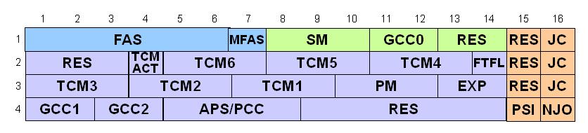
Figure 12 ODUk overhead
5.2.1 Path Monitoring (PM)

Figure 13 ODUk path monitoring overhead
5.2.1.1 Trail Trace Identifier (TTI)
The TTI is a 64-Byte signal that occupies one byte of the frame and is aligned with the OTUk multi-frame. It is transmitted 4 times per multi-frame.
5.2.1.2 BIP-8
This byte provides a bit interleaved parity-8 (BIP-8) code.
The ODUk BIP-8 is computed over the bits in the OPUk (columns 15 to 3824) area of ODUk frame i, and inserted in the ODUk PM BIP-8 overhead location in the ODUk frame i+2.
5.2.1.3 Backward Defect Indication (BDI)
This is defined to convey the “Signal Fail” status detected at the path terminating sink function, to the upstream node.
5.2.1.4 Backward Error Indication and Backward Incoming Alignment Error (BEI/BIAE)
This signal is used to convey in the upstream direction the count of interleaved-bit blocks that have been detected in error by the corresponding ODUk path monitoring sink using the BIP-8 code. This count has nine legal values, namely 0-8 errors. The remaining seven possible values represented by these 4 bits can only result from some unrelated condition and are interpreted as 0 errors.
5.2.1.5 Path Monitoring Status (STAT)
They indicate the presence of a maintenance signal.
5.2.2 Tandem Connection Monitoring (TCM)
There are 6 TCM’s. They can be nested or overlapping.

Figure 14 ODUk tandem connection monitoring #i overhead
5.2.2.1 Trail Trace Identifier (TTI)
The TTI is a 64-Byte signal that occupies one byte of the frame and is aligned with the OTUk multi-frame. It is transmitted four times per multi-frame.
5.2.2.2 BIP-8
This byte provides a bit interleaved parity-8 (BIP-8) code.
Each ODUk BIP-8 is computed over the bits in the OPUk (columns 15 to 3824) area of ODUk frame i, and inserted in the ODUk TCM BIP-8 overhead location (associated with the tandem connection monitoring level) in ODUk frame i+2.
The BIP-8 is only overwritten at the start of a Tandem Connection. Any existing TCM is not overwritten.
5.2.2.3 Backward Defect Indication (BDI)
This is defined to convey the “Signal Fail” status detected at the path terminating sink function, to the upstream node.
5.2.2.4 Backward Error Indication and Backward Incoming Alignment Error (BEI/BIAE)
This signal is used to convey in the upstream direction the count of interleaved-bit blocks that have been detected as being in error by the corresponding ODUk tandem connection monitoring sink using the BIP-8 code. It is also used to convey in the upstream direction an incoming alignment error (IAE) condition that is detected in the corresponding ODUk tandem connection monitoring sink in the IAE overhead.
During an IAE condition the code “1011” is inserted into the BEI/BIAE field and the error count is ignored. Otherwise the error count (0-8) is inserted into the BEI/BIAE field. The remaining 6 possible values represented by these 4 bits can only result from some unrelated condition and are interpreted as 0 errors and BIAE not active.
5.2.2.5 TCM Monitoring Status (STAT)
For each tandem connection monitoring field three bits are defined as status bits (STAT). They indicate the presence of a maintenance signal (if there is an incoming alignment error at the source TCM, or if there is no source TCM active).
5.2.2.6 Tandem Connection Monitoring ACTivation/deactivation (TCM-ACT)
Its definition is for further study.
5.2.3 General Communication Channels (GCC1, GCC2)
Two fields of two bytes are allocated in the ODUk overhead to support two general communications channels between any two network elements with access to the ODUk frame structure (i.e., at 3R regeneration points). These are clear channels. The bytes for GCC1 are located in row 4, columns 1 and 2, and the bytes for GCC2 are located in row 4, columns 3 and 4 of the ODUk overhead.
5.2.4 Automatic Protection Switching and Protection Communication Channel (APS/PCC)
Up to 8 levels of nested APS/PCC signals may be present in this field. The APS/PCC bytes in a given frame are assigned to a dedicated level depending on the value of MFAS as follows:
| MFAS bit 678 | APS/PCC channel applies to connection level | Protection scheme using the APS/PCC channel |
| 000 | ODUk Path | ODUk SNC/N |
| 001 | ODUk TCM1 | ODUk SNC/S, ODUk SNC/N |
| 010 | ODUk TCM2 | ODUk SNC/S, ODUk SNC/N |
| 011 | ODUk TCM3 | ODUk SNC/S, ODUk SNC/N |
| 100 | ODUk TCM4 | ODUk SNC/S, ODUk SNC/N |
| 101 | ODUk TCM5 | ODUk SNC/S, ODUk SNC/N |
| 110 | ODUk TCM6 | ODUk SNC/S, ODUk SNC/N |
| 111 | OTUk Section | ODUk SNC/I |
Table 4 Multi-frame to allow separate APS/PCC for each monitoring level
For linear protection schemes, the bit assignments for these bytes and the bit-oriented protocol are given in ITU-T Recommendation G.873.1. Bit assignment and byte oriented protocol for ring protection schemes are for further study.
5.2.5 Fault Type and Fault Location reporting communication channel (FTFL)
One byte is allocated in the ODUk overhead to transport a 256-byte fault type and fault location (FTFL) message. The byte is located in row 2, column 14 of the ODUk overhead.
5.3 OTUk Overhead and Processing
The OTUk (k = 1,2,3) frame structure is based on the ODUk frame structure and extends it with a forward error correction (FEC). 256 columns are added to the ODUk frame for the FEC and the overhead bytes in row 1, columns 8 to 14 of the ODUk overhead are used for OTUk specific overhead, resulting in an octet-based block frame structure with 4 rows and 4080 columns.
The OTUk forward error correction (FEC) contains the Reed-Solomon RS(255,239) FEC codes. If no FEC is used, fixed stuff bytes (all-0s pattern) are inserted.
OTUk OH information is part of the OTUk signal structure. It includes information for operational functions to support the transport via one or more optical channel connections. The OTUk OH is terminated where the OTUk signal is assembled and disassembled.

Figure 15 OTUk Overhead

Figure 16 OTUk overhead
5.3.1 Scrambling
The OTUk signal needs sufficient bit timing content to allow a clock to be recovered. A suitable bit pattern, which prevents a long sequence of “1”s or “0”s, is provided by using a scrambler.
The operation of the scrambler is functionally identical to that of a frame synchronous scrambler of sequence length 65535 operating at the OTUk rate.
The generating polynomial is 1 + x + x3+ x12 + x16.
The scrambler is reset to “FFFF” (HEX) on the most significant bit of the byte following the last framing byte in the OTUk frame, i.e. the MSB of the MFAS byte. This bit and all subsequent bits to be scrambled are added modulo 2 to the output from the x16 position of the scrambler. The scrambler runs continuously throughout the complete OTUk frame. The framing bytes (FAS) of the OTUk overhead are not scrambled.
Scrambling is performed after FEC check bytes computation and insertion into the OTUk signal.
5.3.2 Frame Alignment Overhead
5.3.2.1 Frame Alignment Signal (FAS)
A 6 byte OTUk-FAS signal is defined in row 1, columns 1 to 6 of the OTUk overhead.
OA1 is “1111 0110”. OA2 is “0010 1000”.

Figure 17 Frame alignment signal overhead structure
5.3.2.2 Multi-Frame Alignment Signal (MFAS)
Some of the OTUk and ODUk overhead signals span multiple OTUk/ODUk frames. A single multi-frame alignment signal (MFAS) byte is defined in row 1, column 7 of the OTUk/ODUk overhead The value of the MFAS byte will be incremented each OTUk/ODUk frame and provides as such a 256 frame multi-frame.
Individual OTUk/ODUk overhead signals use this central multi-frame to lock their 2-frame, 4-frame, 8-frame, 16-frame, 32-frame, etc. multi-frames to the principal frame.
5.3.3 Section Monitoring (SM)

Figure 18 OTUk section monitoring overhead
5.3.3.1 Trail Trace Identifier (TTI)
The TTI is a 64-Byte signal that occupies one byte of the frame and is aligned with the OTUk multi-frame. It is transmitted four times per multi-frame.
5.3.3.2 BIP-8
This byte provides a bit interleaved parity-8 (BIP-8) code.
The OTUk BIP-8 is computed over the bits in the OPUk (columns 15 to 3824) area of OTUk frame i, and inserted in the OTUk BIP-8 overhead location in OTUk frame i+2.
Note: The OPUk includes the Justification Bytes, thus an OTN signal can not be retimed without de-mapping back to the client signal.
5.3.3.3 Backward Defect Indication (BDI)
This is defined to convey the “Signal Fail” Status detected at the Section Terminating Sink Function, to the upstream node.
5.3.3.4 Backward Error Indication and Backward Incoming Alignment Error (BEI/BIAE)
This signal is used to convey in the upstream direction the count of interleaved-bit blocks that have been detected in error by the corresponding OTUk section monitoring sink using the BIP-8 code. It is also used to convey in the upstream direction an incoming alignment error (IAE) condition that is detected in the corresponding OTUk section monitoring sink in the IAE overhead.
During a IAE condition the code “1011” is inserted into the BEI/BIAE field and the error count is ignored. Otherwise the error count (0-8) is inserted into the BEI/BIAE field. The remaining six possible values represented by these four bits can only result from some unrelated condition and are interpreted as 0 errors and BIAE not active.
5.3.3.5 Incoming Alignment Error (IAE)
A single-bit incoming alignment error (IAE) signal is defined to allow the ingress point to inform its peer egress point that an alignment error in the incoming signal has been detected.
IAE is set to “1” to indicate a frame alignment error; otherwise it is set to “0”.
The egress point may use this information to suppress the counting of bit errors, which may occur as a result of a frame phase change of the OTUk at the ingress of the section.
5.3.4 General Communication Channel 0 (GCC0)
Two bytes are allocated in the OTUk overhead to support a general communications channel between OTUk termination points. This is a clear channel. These bytes are located in row 1, columns 11 and 12 of the OTUk overhead.
6 OTN Maintenance Signals
6.1 OTUk maintenance signals
6.1.1 OTUk alarm indication signal (OTUk-AIS)
The OTUk-AIS is a generic-AIS signal. Since the OTUk capacity (130 560 bits) is not an integer multiple of the PN-11 sequence length (2047 bits), the PN-11 sequence may cross an OTUk frame boundary.
The PN-11 sequence is defined by the generating polynomial 1 + x9 + x11.
6.2 ODUk maintenance signals
Three ODUk maintenance signals are defined: ODUk-OCI, ODUk-LCK and ODUk-AIS.
6.2.1 ODUk Open Connection Indication (ODUk-OCI)
ODUk-OCI is specified as a repeating “0110 0110” pattern in the entire ODUk signal, excluding the frame alignment overhead (FA OH) and OTUk overhead (OTUk OH).
The presence of ODUk-OCI is detected by monitoring the ODUk STAT bits in the PM and TCMi overhead fields.
The insertion of this is under management control. There is no defect that inserts ODUk-OCI.
6.2.2 ODUk Locked (ODUk-LCK)
ODUk-LCK is specified as a repeating “0101 0101” pattern in the entire ODUk signal, excluding the Frame Alignment overhead (FA OH) and OTUk overhead (OTUk OH).
The presence of ODUk-LCK is detected by monitoring the ODUk STAT bits in the PM and TCMi overhead fields.
The insertion of this is under management control. There is no defect that inserts ODUk-LCK.
6.2.3 ODUk Alarm Indication Signal (ODUk-AIS)
ODUk-AIS is specified as all “1”s in the entire ODUk signal, excluding the frame alignment overhead (FA OH), OTUk overhead (OTUk OH) and ODUk FTFL.
The presence of ODUk-AIS is detected by monitoring the ODUk STAT bits in the PM and TCMi overhead fields.
ODUk-AIS is generated if the OTUk input signal fails or it detects ODUk-OCI or ODUk-LCK on the input signal.
6.3 Client maintenance signal
6.3.1 Generic AIS for constant bit rate signals
The generic-AIS signal is a signal with a 2047-bit polynomial number 11 (PN-11) repeating sequence.
The PN-11 sequence is defined by the generating polynomial 1 + x9 + x11.
During a signal fail condition of the incoming CBR2G5, CBR10G or CBR40G client signal (e.g. in the case of a loss of input signal), this failed incoming signal is replaced by the generic-AIS signal, and is then mapped into the OPUk.
During signal fail condition of the incoming ODUk/OPUk signal (e.g. in the case of an ODUk-AIS, ODUk-LCK, ODUk-OCI condition) the generic-AIS pattern is generated as a replacement signal for the lost CBR2G5, CBR10G or CBR40G signal.Maintenance Signal Insertion
6.3.2 Client source ODUk-AIS
During a signal fail condition of the incoming ODUj client signal (e.g. OTUj-LOF), this failed incoming signal will be replaced by the ODUj-AIS signal. This ODUj-AIS is then mapped into the respective timeslot in the ODUk.
6.3.3 Client source ODUk-OCI
For the case the ODUj is received from the output of a fabric (ODUj connection function), the incoming signal may contain (case of open matrix connection) the ODUj-OCI signal This ODUj-OCI signal is then mapped into the respective timeslot in the ODUk.
Not all equipment will have a real connection function (switch fabric) implemented; instead the presence/absence of tributary interface port units represents the presence/absence of a matrix connection.
If such unit is intentionally absent or not installed, the associated timeslot in the ODUk shall carry an ODUj-OCI signal.
If such unit is installed but temporarily removed as part of a repair action, the associated timeslot in the ODUk shall carry an ODUj-AIS signal.
7 Defect detection
There are no defects detected in the multiplexer. There are defects detected in the de-multiplexer.
7.1 Default PLM (Payload Mismatch)
Default PLM is declared if the accepted payload type (AcPT) is not equal to the expected payload type(s) as defined by the specific adaptation function. Default PLM is cleared if the accepted payload type is equal to the expected payload type(s).
A new payload type PT (AcPT) is accepted if a new consistent value is received in the PSI[0] byte in 3 consecutive multi-frames.
7.2 Default MSIM (Multiplex Structure Identifier Mismatch supervision)
Default MSIM is declared if the accepted MSI (AcMSI) is not equal to the expected multiplex structure identifier (ExMSI). dMSIM is cleared if the AcMSI is equal to the ExMSI. ExMSI is configured via the management interface. A new multiplex structure identifier MSI (AcMSI) is accepted if a new consistent value is received in the MSI bytes of the PSI overhead (PSI[2…5] for ODU2, PSI[2…17] for ODU3) in 3 consecutive multi-frames.
7.3 Default LOFLOM (Loss of Frame and Multi-frame)
If the frame alignment process is in the out-of-frame (OOF) state for 3 ms, default LOFLOM is declared. To prevent from the case of intermittent OOFs, the integrating timer is reset to 0 until an in-frame (IF) condition persists continuously for 3 ms. Default LOFLOM is cleared when the IF state persists continuously for 3 ms.
The ODUj frame and multi-frame alignment is found by searching for the framing pattern (OA1, OA2 FAS bytes) and checking the multi-frame sequence (MFAS byte) contained in the ODUj frame.
In the out-of-frame state the framing pattern searched for is the full set of the OA1 and OA2 bytes. The in-frame (IF) is entered if this set is found and confirmed one frame period later and an error-free multi-frame sequence is found in the MFAS bytes of the two frames.
In the in-frame state (IF) the frame alignment signal is continuously checked with the presumed frame start position and the expected multi-frame sequence. The framing pattern checked for is the OA1OA2 pattern (bytes 3 and 4 of the first row of the ODUj[/i] frame). The out of frame state (OOF) is entered if this subset is not found at the correct position in 5 consecutive frames or the received MFAS does not match with the expected multi-frame number in 5 consecutive frames.
The frame and multi-frame start are maintained during the OOF state.
There is one of these defects for each tributary.
8 Synchronization
8.1 Introduction
OTN is transparent to the payload it transports within the ODUk. The OTN layer does not need to transport network synchronization since network synchronization can be transported within the payload, mainly by SDH client tributaries.
Two types of mapping have been specified for the transport of CBR payload, e.g. SDH.
The first one is the asynchronous mapping, which is the most widely used, where the payload floats within the OTN frame. In this case, there is no frequency relationship between the payload and the OTN frame frequencies, thus simple free running oscillators can be used to generate the OTN frame.
The second is the synchronous mapping where the timing used to generate the OTN frame is extracted from a CBR client tributary, e.g. SDH. In case of LOS of the input client, the OTN frequency that does not transport payload is generated by a free running oscillator, without need for a holdover mode.
This specification allows for very simple implementation of timing in OTN equipments compared to SDH.
An OTN NE does not require synchronization interfaces, complex clocks with holdover mode nor SSM processing. Another difference with SDH is that there is no geographical option for the timing aspects of OTN.
OTN transports client signals into a G.709 frame, OTUk that is transported by an OCh on one lambda of the Optical Transport Module (OTM). Each lambda carries its G.709 frame with its own frequency; there is no common clock for the different OTUk of the OTM.
A trail through OTN is generated in an OTN NE that maps the client into an ODUk and terminated in another OTN NE that de-maps the client signal from the ODUk. Between the 2 OTN trail terminations, there might be 3R regenerators, which are equipments that perform complete regeneration of the pulse shape, clock recovery and retiming within required jitter limits.
The number of 3R regenerators that can be cascaded in tandem depends on the specification of this regenerator and on the jitter and wander generation and tolerance applicable to the OTUk interfaces; it is stated to be at least 50.
ODUk multiplexing has been standardized; its implication on timing has been taken into account in the relevant recommendations.
8.2 Network requirements
In an OTN, jitter and wander accumulate on transmission path according to the generation and transfer characteristics of interconnected equipments, 3R regenerators, client mappers, de-mappers and multiplexers, de-multiplexers. In order to avoid the effects of excessive jitter and wander, the ITU-T Recommendation G.8251 recommendation specifies the maximum magnitude of jitter and wander, and the minimum jitter and wanders tolerance, at OTN network interfaces.
The OTN generates and accumulates jitter and wander on its client signals due to the buffers of the mapping into ODUk and due to the ODUk multiplexing. The limits for such accumulation are given in the ITU-T Recommendation G.825 for SDH signal clients.
Jitter and wander is also accumulated on the OTN signals itself due to the ODUk multiplexing and 3R jitter generation. The network limits for this are given in the ITU-T Recommendation G.8251.
The ITU-T Recommendation G.8251 specifies the jitter and wander tolerance. As OTN clocks do not generate wander, no wander limit has been defined for OTN.
The ITU-T Recommendation G.8251 specifies the different type of clocks that are required to perform the following functions: the accuracy of these clocks depends on the definition of the G.709 frame and on the accuracy specified for the clients.
- Asynchronous mapping of a client into an ODUk and ODUk multiplexing: this ODCa clock is a free- running clock with a frequency accuracy of ± 20 ppm.
- Synchronous mapping of a client into an ODUk: this ODCb clock is locked on the client frequency.
- 3R regeneration: this ODCr clock is locked on an OCh input frequency which must be within ± 20 ppm.
- De-mapping a client signal from an ODUk and ODUk de-multiplexing: this ODCp clock is locked on an OCh input frequency which must be within ± 20 ppm.
The ITU-T Recommendation G.8251 specifies the jitter generation of these clocks and, when applicable, noise tolerance, jitter transfer and transient response.
All these clock functions are used for clock recovery and clock filtering of a particular signal. They never serve as an equipment synchronization source. Therefore there is no holdover mode specified for these clocks since there is no need for an accurate clock when the input signal disappears.
The ITU-T Recommendation G.8251 provides a provisional adaptation of the SDH synchronization reference chain to include OTN islands. This is an amendment of the reference chain being defined in the ITU-T Recommendation G.803. Considering that SDH may be transported by OTN islands, the SEC will no longer be present but replaced by OTN NEs. This leads to the definition of a reference chain where all SECs located between 2 SSUs are replaced by an OTN island. The local part of the reference chain, after the last SSU can still support 20 SECs in tandem. Each of these islands may be composed of OTN NEs performing mapping/de-mapping or multiplexing/de-multiplexing operations. This adaptation of the reference chain raises a buffer size constraint for the OTN NEs in order to keep the overall network wander performance within specified limits. Predominantly the mapping and the de-mapping functions of the OTN contribute to wander accumulation due to the buffers being involved in these functions. The size limit of these buffers is specified in the ITU-T Recommendation G.798. This allows inserting up to 10 mapping/ multiplexing nodes per OTN island. A total of 100 mapping/de-mapping functions can be performed on this synchronization reference chain.
The ITU-T Recommendation G.8251 presents a Hypothetic Reference Model for 3R regenerator jitter accumulation: according to this model, at any OTUk interface the jitter will remain within network limits in a chain of one mapping clock and up to 50 cascaded 3R regenerators plus a de-mapping clock. It reports the results of extensive simulations showing that it is possible to have 50 OTN regenerators without exceeding the network limits of OTUk interfaces, assuming the regenerators comply with the model defined in this Recommendation.
9 Why use OTN
OTN offers the following advantages relative to SDH:
- Stronger Forward Error Correction (FEC)
- More levels of Tandem Connection Monitoring (TCM)
- Transparent transport of client signals
- Switching scalability
OTN has the following disadvantages:
- Requires new hardware and management system
9.1 Forward Error Correction (FEC)
Forward error correction is a major feature of the OTN.
Already SDH has a FEC defined. It uses undefined SOH bytes to transport the FEC check information and is therefore called an in-band FEC. It allows only a limited number of FEC check information, which limits the performance of the FEC.
For the OTN a Reed-Solomon 16 byte-interleaved FEC scheme is defined, which uses 4 x 256 bytes of check information per ODU frame.

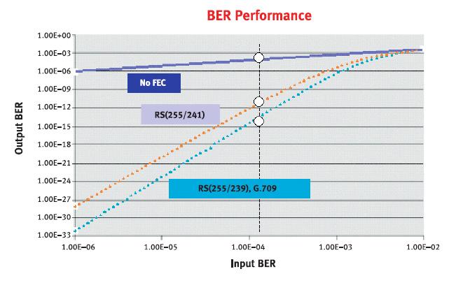
Figure 19 Error correction in OTN
According to ITU-T Recommendation G.709, an Reed-Solomon (255, 239) code with a symbol size of 8 is used for FEC. 239 input bytes are encoded in 255 output bytes. This code enables the detection of 2t = (n – k) = 16 errors in a codeword and the correction of t = (n – k)/2 = 8 of them.
FEC has been proven to be effective in OSNR limited systems as well as in dispersion limited systems. As for non-linear effects, reducing the output power leads to OSNR limitations, against which FEC is useful. FEC is less effective against PMD, however.
G.709 defines a stronger Forward Error Correction for OTN that can result in up to 6,2 dB improvement in Signal to Noise Ratio (SNR). Another way of looking at this is that to transmit a signal at a certain Bit Error Rate (BER) with 6,2 dB less power than without such a FEC.
The coding gain provided by the FEC can be used to:
- Increase the maximum span length and/or the number of spans, resulting in an extended reach. (Note that this assumes that other impairments like chromatic and polarization mode dispersion are not becoming limiting factors.)
- Increase the number of DWDM channels in a DWDM system which is limited by the output power of the amplifiers by decreasing the power per channel and increasing the number of channels. (Note that changes in non-linear effects due to the reduced per channel power have to be taken into account.)
- Relax the component parameters (e.g. launched power, eye mask, extinction ratio, noise figures, and filter isolation) for a given link and lower the component costs.
- but the most importantly the FEC is an enabler for transparent optical networks:
Transparent optical network elements like OADMs introduce significant optical impairments (e.g. attenuation). The number of transparent optical network elements that can be crossed by an optical path before 3R regeneration is needed is therefore strongly limited. With FEC an optical path can cross more transparent optical network elements.
This allows evolving from today’s point-to-point links to transparent, meshed optical networks with sufficient functionality.
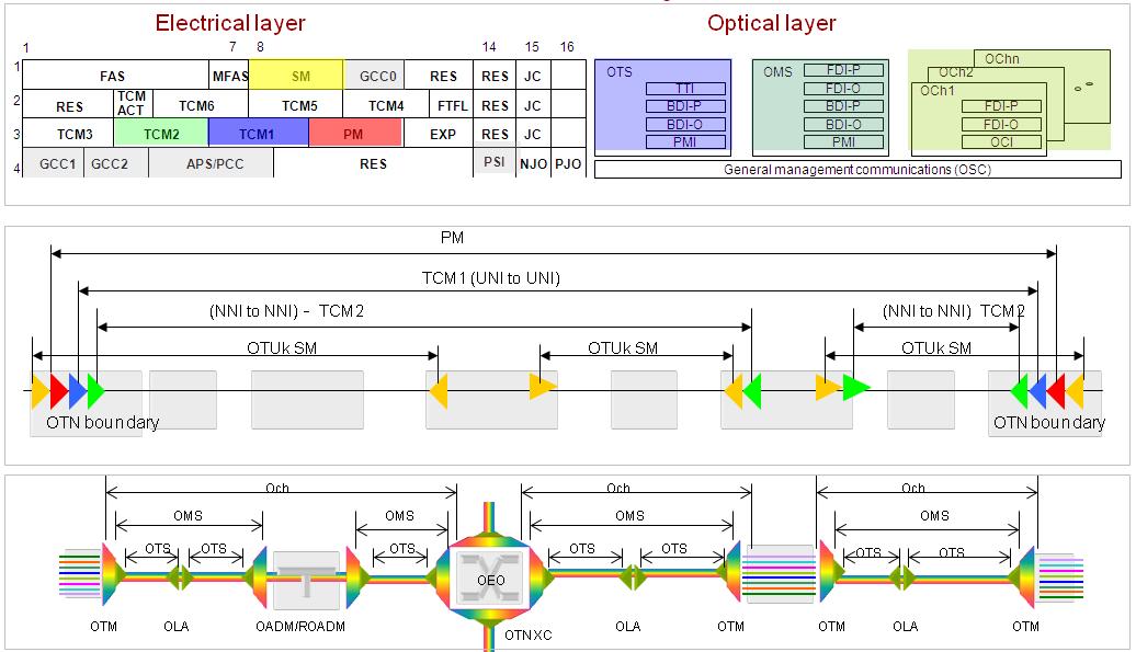
9.2 Tandem Connection Monitoring
SDH monitoring is divided into section and path monitoring. A problem arises when you have “Carrier’s Carrier” situation where it is required to monitor a segment of the path that passes another carrier network.

Figure 20 Tandem Connection Monitoring
Here Operator A needs to have Operator B carries his signal. However he also needs a way of monitoring the signal as it passes through Operator B’s network. This is what a “Tandem connection” is. It is a layer between Line Monitoring and Path Monitoring. SDH was modified to allow a single Tandem connection. G.709 allows 6.
TCM1 is used by the User to monitor the Quality of Service (QoS) that they see. TCM2 is used by the first operator to monitor their end-to-end QoS. TCM3 is used by the various domains for Intra domain monitoring. Then TCM4 is used for protection monitoring by Operator B.
There is no standard on which TCM is used by whom. The operators have to have an agreement, so that they don’t conflict.
TCM’s also support monitoring of ODUk (G.709 w/o FEC) connections for one or more of the following network applications (refer to ITU-T G.805 and ITU-T G.872):
- optical UNI to UNI tandem connection monitoring; monitoring the ODUk connection through the public transport network (from public network ingress network termination to egress network termination);
- optical NNI to NNI tandem connection monitoring; monitoring the ODUk connection through the network of a network operator (from operator network ingress network termination to egress network termination);
- sub-layer monitoring for linear 1+1, 1:1 and 1:n optical channel sub-network connection protection switching, to determine the signal fail and signal degrade conditions;
- sub-layer monitoring for optical channel shared protection ring (SPRING) protection switching, to determine the signal fail and signal degrade conditions;
- Monitoring an optical channel tandem connection for the purpose of detecting a signal fail or signal degrade condition in a switched optical channel connection, to initiate automatic restoration of the connection during fault and error conditions in the network;
- Monitoring an optical channel tandem connection for, e.g., fault localization or verification of delivered quality of service.
A TCM field is assigned to a monitored connection. The number of monitored connections along an ODUk trail may vary between 0 and 6. Monitored connections can be nested, overlapping and/or cascaded.

Figure 21 ODUk monitored connections
Monitored connections A1-A2/B1-B2/C1-C2 and A1-A2/B3-B4 are nested, while B1-B2/B3-B4 are cascaded.
Overlapping monitored connections are also supported.

Figure 22 Overlapping ODUk monitored connections
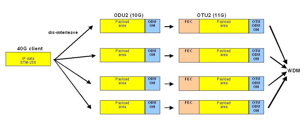
9.3 Transparent Transport of Client Signals
G.709 defines the OPUk which can contain the entire SDH signal. This means that one can transport 4 STM-16 signals in one OTU2 and not modify any of the SDH overhead.
Thus the transport of such client signals in the OTN is bit-transparent (i.e. the integrity of the whole client signal is maintained).
It is also timing transparent. The asynchronous mapping mode transfers the input timing (asynchronous mapping client) to the far end (asynchronous de-mapping client).
It is also delay transparent. For example if 4 STM-16 signals are mapped into ODU1’s and then multiplexed into an ODU2, their timing relationship is preserved until they are de-mapped back to ODU1’s.
9.4 Switching Scalability
When SDH was developed, its main purpose was to provide the transport technology for voice services. Two switching levels were therefore defined. A low order switching at VC-12 level supports directly the E1 voice signals and a high order switching level at VC-4 level is used for traffic engineering. Switching levels at higher bit rates were not foreseen.
Over time the line rate increased while the switching rate was fixed. The gap between line rate and switching bit rate widened. Furthermore new services at higher bit rates (IP, Ethernet services) had to be supported.
Contiguous and virtual concatenation were introduce in order to solve part of the services problem as they allow to support services above the standard SDH switching bit rates.
The gap between line or service bit rate and switching bit rate however still exists as even with concatenation switching is performed at the VC-4 level.
For a 4 x 10G to 40G SDH multiplexer this means processing of 256 VC-4. This will result not only in efforts in the equipment hardware, but also in management and operations efforts.
For efficient equipment and network design and operations, switching at higher bit rates has to be introduced.
One could now argue that photonic switching of wavelengths is the solution. But with photonic switching the switching bit rate is bound to the bit rate of the wavelength and as such would be the service. An independent selection for service bit rates and DWDM technology is not possible.
A operator offering 2,5 Gbit/s IP interconnection would need a N x 2G5 DWDM system. When adding 10G services he has to upgrade some of its wavelengths to 10G. This would lead to inefficient network designs.
OTN provides the solution to the problem by placing no restrictions on switching bit rates. As the line rate grows new switching bit rates are added.
An operator can offer services at various bit rates (2G5, 10G …) independent of the bit rate per wavelength using the multiplexing and inverse multiplexing features of the OTN.
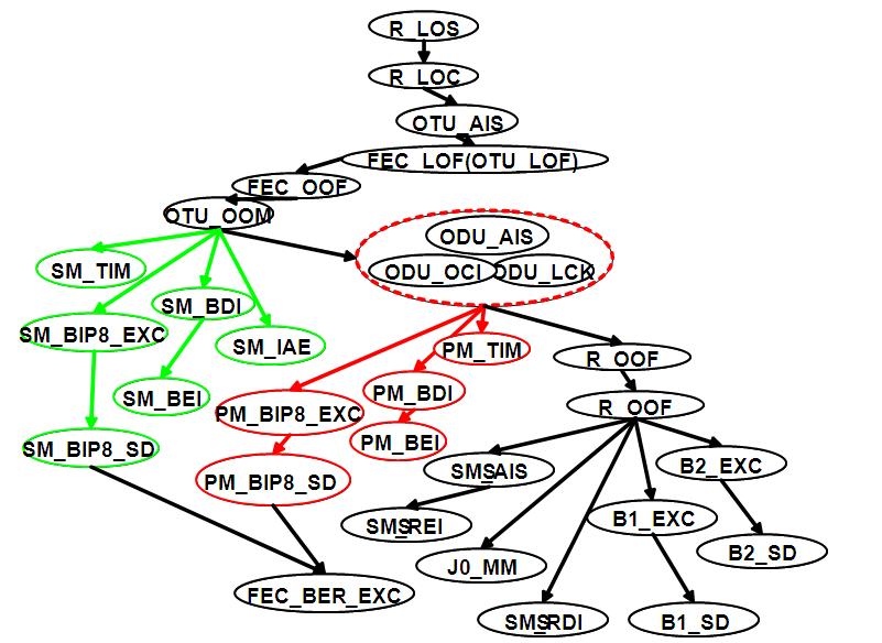
OTN ALARM FLOW

Related Articles on MapYourTech


Continue Reading This Article
Sign in with a free account to unlock the full article and access the complete MapYourTech knowledge base.


