Tag

Optical transport network

Browsing

As the 5G era dawns, the need for robust transport network architectures has never been more critical. The advent of 5G brings with it a promise of unprecedented data speeds and connectivity, necessitating a backbone capable of supporting a vast array of services and applications. In this realm, the Optical Transport Network (OTN) emerges as a key player, engineered to meet the demanding specifications of 5G’s advanced network infrastructure.

Understanding OTN’s Role

The 5G transport network is a multifaceted structure, composed of fronthaul, midhaul, and backhaul components, each serving a unique function within the overarching network ecosystem. Adaptability is the name of the game, with various operators customizing their network deployment to align with individual use cases as outlined by the 3rd Generation Partnership Project (3GPP).

C-RAN: Centralized Radio Access Network

In the C-RAN scenario, the Active Antenna Unit (AAU) is distinct from the Distribution Unit (DU), with the DU and Central Unit (CU) potentially sharing a location. This configuration leads to the presence of fronthaul and backhaul networks, and possibly midhaul networks. The fronthaul segment, in particular, is characterized by higher bandwidth demands, catering to the advanced capabilities of technologies like enhanced Common Public Radio Interface (eCPRI).

CRAN
5G transport network architecture: C-RAN

C-RAN Deployment Specifics:

  • Large C-RAN: DUs are centrally deployed at the central office (CO), which typically is the intersection point of metro-edge fibre rings. The number of DUs within in each CO is between 20 and 60 (assume each DU is connected to 3 AAUs).
  • Small C-RAN: DUs are centrally deployed at the metro-edge site, which typically is located at the metro-edge fibre ring handover point. The number of DUs within each metro-edge site is around 5~10

D-RAN: Distributed Radio Access Network

The D-RAN setup co-locates the AAU with the DU, eliminating the need for a dedicated fronthaul network. This streamlined approach focuses on backhaul (and potentially midhaul) networks, bypassing the fronthaul segment altogether.

5G transport network architecture: D-RAN

NGC: Next Generation Core Interconnection

The NGC interconnection serves as the network’s spine, supporting data transmission capacities ranging from 0.8 to 2 Tbit/s, with latency requirements as low as 1 ms, and reaching distances between 100 to 200 km.

Transport Network Requirement Summary for NGC:

ParameterRequirementComments
Capacity0.8-2 Tbit/sEach NGC node has 500 base stations. The average bandwidth of each base station is about 3Gbit/s, the convergence ratio is 1/4, and the typical bandwidth of NGC nodes is about 400Gbit/s. 2~5 directions are considered, so the NGC node capacity is 0.8~2Tbit/s.
Latency1 msRound trip time (RTT) latency between NGCs required for DC hot backup intra-city.
Reach100-200 kmTypical distance between NGCs.

Note: These requirements will vary among network operators.

The Future of 5G Transport Networks

The blueprint for 5G networks is complex, yet it must ensure seamless service delivery. The diversity of OTN architectures, from C-RAN to D-RAN and the strategic NGC interconnections, underscores the flexibility and scalability essential for the future of mobile connectivity. As 5G unfolds, the ability of OTN architectures to adapt and scale will be pivotal in meeting the ever-evolving landscape of digital communication.

References

https://www.itu.int/rec/T-REC-G.Sup67/en

Signal integrity is the cornerstone of effective fiber optic communication. In this sphere, two metrics stand paramount: Bit Error Ratio (BER) and Q factor. These indicators help engineers assess the performance of optical networks and ensure the fidelity of data transmission. But what do these terms mean, and how are they calculated?

What is BER?

BER represents the fraction of bits that have errors relative to the total number of bits sent in a transmission. It’s a direct indicator of the health of a communication link. The lower the BER, the more accurate and reliable the system.

ITU-T Standards Define BER Objectives

The ITU-T has set forth recommendations such as G.691, G.692, and G.959.1, which outline design objectives for optical systems, aiming for a BER no worse than 10−12 at the end of a system’s life. This is a rigorous standard that guarantees high reliability, crucial for SDH and OTN applications.

Measuring BER

Measuring BER, especially as low as 10−12, can be daunting due to the sheer volume of bits required to be tested. For instance, to confirm with 95% confidence that a system meets a BER of 10−12, one would need to test 3×1012 bits without encountering an error — a process that could take a prohibitively long time at lower transmission rates.

The Q Factor

The Q factor measures the signal-to-noise ratio at the decision point in a receiver’s circuitry. A higher Q factor translates to better signal quality. For a BER of 10−12, a Q factor of approximately 7.03 is needed. The relationship between Q factor and BER, when the threshold is optimally set, is given by the following equations:

The general formula relating Q to BER is:

bertoq

A common approximation for high Q values is:

ber_t_q_2

For a more accurate calculation across the entire range of Q, the formula is:

ber_t_q_3

Practical Example: Calculating BER from Q Factor

Let’s consider a practical example. If a system’s Q factor is measured at 7, what would be the approximate BER?

Using the approximation formula, we plug in the Q factor:

This would give us an approximate BER that’s indicative of a highly reliable system. For exact calculations, one would integrate the Gaussian error function as described in the more detailed equations.

Graphical Representation

ber_t_q_4

The graph typically illustrates these relationships, providing a visual representation of how the BER changes as the Q factor increases. This allows engineers to quickly assess the signal quality without long, drawn-out error measurements.

Concluding Thoughts

Understanding and applying BER and Q factor calculations is crucial for designing and maintaining robust optical communication systems. These concepts are not just academic; they directly impact the efficiency and reliability of the networks that underpin our modern digital world.

References

https://www.itu.int/rec/T-REC-G/e

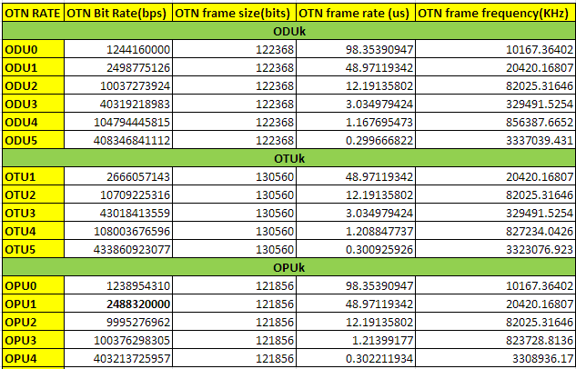
**Multiplicative factor is just a simple math :eg. for ODU1/OPU1=3824/3808={(239*16)/(238*16)}

Here value of multiplication factor will give the number of times for rise in the frame size after adding header/overhead.

Example:let consider y=(x+delta[x])/xIn terms of OTN frame here delta[x] is increment of Overhead.

As we are using Reed Soloman(255,239) i.e we are dividing 4080bytes in sixteen frames (The forward error correction for the OTU-k uses 16-byte interleaved codecs using a Reed- Solomon S(255,239) code. The RS(255,239) code operates on byte symbols.).Hence 4080/16=255.

Try to understand using OTN frames now. I have tried to make it legible.

As we know that OPU1 payload rate= 2.488 Gbps (OC48/STM16) and is  frame size is 4*3808 as below.

*After adding OPU1 and ODU1 16 bytes overhead: Frames could be fragmented into following number of chunks.

3808/16 = 238, (3808+16)/16 = 239

So, ODU1 rate: 2.488 x 239/238** ~ 2.499Gbps

*Now after adding  FEC bytes

OTU1 rate: ODU1 x 255/239 = 2.488 x 239/238 x 255/239

=2.488 x 255/238 ~2.667Gbps


Now let’s have a small discussion over different multiplier and divisor scenarios that will make it clearer to understand.

We know that an OTU frame 4 * 4080 bytes (= 255 * 16 * 4)

OPU representing the Payload (3824-16) * 4 * 4 = 3808 bytes (= 238 * 16 * 4) .

OPU1 is exactly the rate of STM-16.

Now,

ODU1 = (3824/3808) * OPU1 = ((16 * 239) / (238 16 *)) * OPU1 = (239/238) * STM-16

OTU1 = (4080/3808) * OPU1 = ((255 * 16) / (238 * 16)) * OPU1 = (255/238) * STM-16


OPU2 contains 16 * 4 = 64 bytes of fixed stuff (FS) added to the 1905 to 1920 .

OPU2 * ((238 * 16 * 4-16 * 4) / (238 * 16 * 4)) = STM-64 rate

OPU2 = 238 / (238-1) * STM-64 = 238/237* STM-64 rate

ODU2 = (239/237) * STM-64 rate ,

similarly


OTU2 = ( 255/237) * STM-64 rate

OPU3 Including 2 * 16 * 4 = 128 fixed stuff (FS) bytes added to the 1265 ~ 1280 and 2545 ~ 2560

OPU3 * ((238 * 16 * 4-2 * 16 * 4) / (238 * 16 * 4)) = rate of STM-256

OPU3 = 238 / (238-2) * STM-256 = 238/236 * STM-256

ODU3 = (239 / 236) * STM-256

OTU3 = (255/236) * STM-256

The OTU4 was required to transport ten ODU2e signals, which have a non-SDH based clock frequency as basis. The OTU4 clock should be based on the same SDH clock as the OTU1, OTU2 and OTU3 and not on the 10GBASE-R clock, which determines the ODU2e frequency. An exercise was performed to determine the necessary divider in the factor 255/divider, and the value 227 was found to meet the requirements (factor 255/227). Note that this first analysis has indicated that a future 400 Gbit/s OTU5 could be created using a factor 255/226 and a 1 Tbit/s OTU6 using a factor 255/225.