
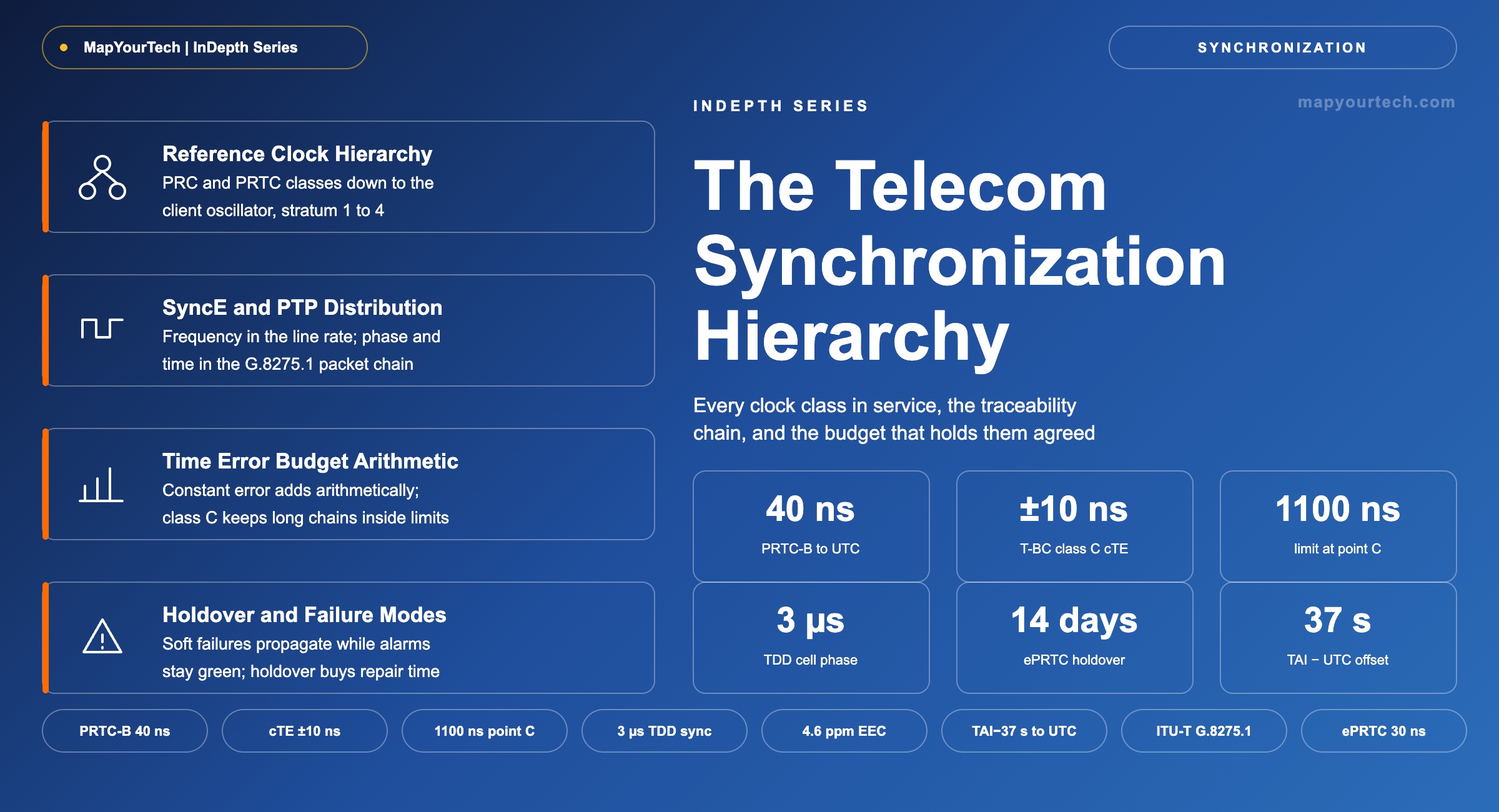
Clock Types and the Telecom Synchronization Hierarchy
Every clock class a transport network carries, the traceability rules that connect them, and how the same hierarchy serves an SDH span, a 400G coherent line system, a 5G fronthaul link and the requirements now forming for 6G.
Every clock is wrong; the hierarchy decides by how much.
1. Introduction
A time server in an Australian carrier's network restarted on 8 July 2026, read a GPS week count it had not been patched to interpret, and set its clock to 2006. It then did what a time server does and published that date to everything downstream, taking a national mobile network off the air for most of a working day. The operator's own submission to the subsequent senate hearing described two contributing causes: an undocumented configuration change that had promoted the unit to act as its own stratum 1 authority, and a software update available since early 2026 that had not been applied (operator statement, reported in trade press). No fibre was cut, no traffic engineering failed and no radio was misconfigured. The network stopped agreeing with itself about what time it was.
Synchronization sits underneath every other transport function, which is why its failures look like everything failing at once. Time-division duplex (TDD) radio needs neighbouring cells to agree on frame boundaries within 3 µs (standard-specified, 3GPP TS 38.133) or they transmit into each other's receive windows. Coherent line systems need a stable frequency reference to keep mapping and demapping buffers from slipping. Billing records, lawful intercept, distributed databases and performance measurement all rest on timestamps that mean the same thing at both ends of a path. The mechanisms that deliver those guarantees are a hierarchy of clocks, each specified against the one above it, and a set of protocols that move frequency, phase and time between them.
Two families of specification govern that hierarchy. The ITU-T G.81x and G.82xx series define the clocks and the network limits: the primary reference clock, the synchronization supply unit, the equipment clock, the primary reference time clock, the telecom boundary clock and the telecom time slave clock, along with the maximum error each may add. IEEE 1588 defines the packet protocol that carries time, and the ITU-T telecom profiles constrain that protocol into something an operator can engineer and verify. Around both sits a distribution layer: Synchronous Ethernet for frequency at the physical layer, Precision Time Protocol for phase and time at the packet layer, and Global Navigation Satellite System receivers supplying traceability to Coordinated Universal Time at chosen points.
The clock names, their specifications, the traceability rules that connect them and the arithmetic that turns a component limit into a network budget are what follow. The same hierarchy applies to an SDH span commissioned in 1998 and to a 5G fronthaul link commissioned last month, because the physics of an oscillator drifting has not changed; what changed is how little error the applications on top will now tolerate. MapYourTech's companion treatment of timing and synchronization in telecommunication networks covers the vocabulary at a lighter depth; this article works down to the clock specifications and the budget arithmetic.
2. Frequency, Phase and Time Definitions
Network synchronization is the distribution of three separate quantities across a transport network: frequency, the rate at which a clock advances; phase, the alignment of its significant instants against a reference; and time of day, the label attached to those instants on a named time scale such as Coordinated Universal Time (UTC).
Each quantity is a stricter condition than the one before it. Two clocks can hold identical frequency while their edges never coincide. Two clocks can align their edges perfectly while disagreeing by six hours about which second those edges belong to. Only the third condition, time alignment, gives both clocks the same reading for the same physical instant.
2.1 Clock, Timing and Synchronization as Distinct Terms
Three words carry most of the traffic in this field and are routinely swapped for one another, which matters because each names a different object in a specification. A clock is a device. Timing is what that device produces and what the network carries. Synchronization is the process that brings clocks into agreement and keeps them there. An alarm that reports a clock failure may mean the oscillator has degraded, the reference has disappeared, or the selection process has run out of candidates, and those three conditions call for three different responses.
| Term | What it denotes | How it is specified | Common misuse |
|---|---|---|---|
| Clock | A device: an oscillator, a counter and a control loop that steers the oscillator toward a reference | Free-run accuracy, holdover stability, noise generation and tolerance — ITU-T G.811, G.812, G.8262, G.8273.2 | Blamed for a failure that belongs to its reference |
| Timing | The information a clock produces and the network distributes: frequency, phase, time of day | In Hz, ns and UTC seconds; carried by SyncE, PTP, 1 PPS and time-of-day interfaces | Used as a synonym for synchronization |
| Synchronization | The process and the network function that bring clocks into agreement and hold them there | Reference qualification, selection, servo behaviour, holdover; measured as time error against a reference | Used to mean the clock, or to mean frequency alone |
| Syntonization | Agreement in frequency only, with no constraint on phase or on the time scale | Fractional frequency offset, dimensionless or in ppb | Assumed to imply time alignment, which it does not |
| Traceability | The property that an unbroken chain of specified comparisons links a clock to a recognized standard | Advertised in ESMC quality levels and PTP clockClass; chain length countable through the extended QL TLV | Assumed from topology rather than verified from what the network advertises |
The distinction has an operational edge. Synchronous Ethernet syntonizes a chain of nodes and delivers nothing about phase; a node can be perfectly syntonized and still be a second away from its neighbour on time of day. Conversely a node holding valid time of day from a satellite receiver may be running on a free-drifting oscillator between satellite fixes. Reading a status display starts with asking which of the three the indicator refers to.
2.2 Distinction Between Adjacent Quantities
Three pairs of terms account for most of the confusion in synchronization engineering, and each pair separates cleanly once the units are written down.
Frequency accuracy against phase error. Frequency accuracy is dimensionless, expressed as a fraction such as 1 × 10⁻¹¹ or in parts per billion; phase error is a time, expressed in nanoseconds. A frequency offset does not stay a frequency offset. Left running, it integrates into phase error at a constant rate, which is why a frequency specification always implies a phase budget over some interval.
Phase alignment against time alignment. Phase alignment constrains where an edge falls; time alignment additionally constrains what number that edge is called. A radio unit performing time-division duplex needs phase alignment to avoid interfering with its neighbour. A billing record or a lawful intercept timestamp needs time alignment, because the number itself is the deliverable.
Four time scales sit behind any time-of-day reading, and confusing them produces errors of exactly known size. International Atomic Time (TAI) is continuous and carries no leap seconds. UTC is TAI adjusted by leap seconds; 27 have been inserted, and the standing offset is TAI − UTC = 37 s (published value, BIPM, unchanged since the most recent insertion). GPS time is continuous from its epoch of 6 January 1980 and currently runs 18 s ahead of UTC. The PTP timescale is likewise continuous and TAI-aligned; the Announce message carries a currentUtcOffset field and leap flags so a receiver can render UTC from it.
Read the Full Analysis with Premium
The remaining 88% of this article — the design numbers, trade-offs and field guidance — is part of MapYourTech Premium, along with the full premium library, courses and professional tools.
You May Also Like

-
Free
-
September 4, 2026

-
Premium
-
September 4, 2026

-
Premium
-
September 4, 2026