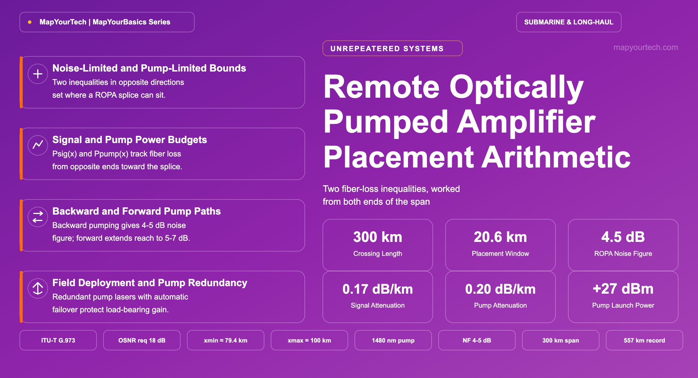
Remote Optically Pumped Amplifier Placement Arithmetic
The window a ROPA can occupy, bounded by the pump power that reaches it and the noise it adds to an already-attenuated signal.
The worst span sets the budget, whatever the average says.
Introduction
A remote optically pumped amplifier — ROPA — is a splice, not a site. Where a repeatered submarine or terrestrial crossing places a powered erbium-doped fiber amplifier (EDFA) every 60–100 km, an unrepeatered link puts nothing but glass between the two terminal buildings, and any gain applied partway through the span has to arrive as light, not electricity. A ROPA is how that gain gets there: a short length of erbium-doped fiber spliced directly into the transmission path, pumped by laser light launched from one of the terminals and delivered down the fiber itself.
The placement of that splice is not a free choice. Move it too close to the terminal that is not doing the pumping, and the residual pump power reaching it — after however many kilometres of fiber attenuation the pump band has already suffered — drops below what the erbium ions need to invert. Move it too close to the terminal that is doing the pumping, and the signal arriving at the splice has already crossed most of the span on its own, weak enough that the ROPA's own amplified spontaneous emission (ASE) does more damage to the link's optical signal-to-noise ratio (OSNR) than the added gain recovers. Between those two failure modes sits a window, typically tens of kilometres wide, fixed by four numbers an engineer already carries on the link budget sheet: two launch powers and two fiber attenuation coefficients.
This article derives that window in closed form, states the governing inequality on each side, and carries one stated crossing through the arithmetic to a placement distance. The scope is a single backward-pumped ROPA on a single-span unrepeatered link; dual-ROPA crossings and the full nonlinear noise budget of the line sit outside it, noted only where they change which bound binds first.
Remote Optically Pumped Amplifier Definition
A remote optically pumped amplifier is a length of erbium-doped fiber spliced into a transmission span at a point with no local electrical supply, its population inversion sustained solely by pump light launched from a terminal kilometres away and carried to the splice through the transmission fiber or a dedicated pump-delivery fiber.
Three adjacent quantities get folded into "ROPA" in casual usage, and each names a different mechanism. A ROPA supplies gain at one point; distributed Raman amplification, covered in a companion treatment of distributed Raman amplification, supplies gain continuously along the fiber by pumping the transmission fiber itself as the gain medium, with no erbium and no discrete splice. A ROPA carries no electronics of its own; an active in-line amplifier or repeater draws electrical power from a copper feed in the cable and can be power-cycled, monitored locally, and swapped without touching the placement arithmetic that governs the ROPA's position. A ROPA is purely optical and does not touch the bit stream; a regenerative site converts the signal to the electrical domain, retimes and reshapes it, and restarts the noise budget from zero — a capability no optical amplifier, remote or local, provides.
Fiber attenuation converts a distance to a loss in one line, run in both directions along the span: Loss(dB) = α(dB/km) × distance(km). Over 90 km of fiber attenuating at 0.20 dB/km, the pump is attenuated by 18 dB — a factor of about 63× in power — before it ever reaches the erbium.
Takeaway: A ROPA moves gain into the span without moving power into it; the arithmetic that decides where it can sit is fiber loss run in two directions from two different starting points.
Erbium Gain Mechanism and Pump Path Options
Erbium ions in the fiber core sit in three relevant energy states, and a pump photon at 980 nm or 1480 nm lifts an ion from the ground state to an excited state from which it decays, within about ten milliseconds, to a longer-lived metastable level. A signal photon at a wavelength the metastable level can emit — the C-band, 1530–1565 nm — stimulates that decay and is copied, in phase and wavelength, by the emitted photon. Repeat this across enough excited ions along the erbium-doped fiber and the input signal leaves amplified. Every EDFA runs on this mechanism, covered in more depth in a dedicated treatment of EDFA noise figure; what a ROPA adds is distance between the pump laser and the fiber it pumps.
Two pump wavelengths are available, and the choice is not interchangeable, a point examined in detail in a short discussion of 980 nm and 1480 nm EDFA pumping. A 980 nm pump reaches closer to the 3 dB quantum limit on noise figure than a 1480 nm pump does, but 980 nm light attenuates faster in silica than 1480 nm light, so a 980 nm pump loses more of its power over the same delivery distance. For a splice sitting tens of kilometres from its pump laser, that difference decides the wavelength: unrepeatered ROPA designs in current practice pump at 1480 nm, trading a higher noise figure — typically 4–7 dB depending on pump direction — for pump-delivery reach a 980 nm source could not sustain.
Backward and Forward Pump Directionality
Pump light can reach the ROPA from either terminal. Backward pumping launches the pump from the receive terminal, so it travels opposite the signal; forward pumping launches from the transmit terminal and co-propagates with the signal. The two configurations differ in noise figure and in how far into the span the ROPA can sit (Figure 2).
Backward pumping is the default in current practice. Because the ROPA typically sits closer to the terminal doing the pumping than to the far terminal, the pump has travelled a shorter distance and arrives stronger, giving the erbium fiber a higher inversion state and a lower noise figure — typically 4–5 dB [vendor-reported / measured range]. Forward pumping trades some of that margin for reach: because pump and signal now decay together from the transmit terminal, a forward-pumped ROPA can sit farther into the span than a backward pump alone would reach, at a noise figure that typically runs 5–7 dB. The longest unrepeatered crossings pair both, described further in an overview of unrepeatered submarine transmission systems: a forward-pumped ROPA nearer the transmit terminal and a backward-pumped ROPA nearer the receive terminal, each covering the part of the span the other cannot reach economically.
The backward-pumped case, the more common single-ROPA configuration, governs the arithmetic below, with x measured from the pumping terminal in that direction.
Signal and Pump Power Budgets Along the Span
Fix a coordinate: let x be the distance from Terminal B, the terminal launching the backward pump, to the ROPA splice. The total crossing length is L, so the ROPA sits (L−x) km from Terminal A, the terminal launching the signal.
Two independent attenuation processes act on the two things travelling toward the splice from opposite ends. The signal, launched from Terminal A at Plaunch (dBm per channel, measured at the booster output), covers (L−x) km of signal-band fiber before it reaches the ROPA:
The pump, launched from Terminal B at Ppump,launch (dBm), covers x km of pump-band fiber — the same physical fiber pair in most backward-pumped designs, at a different wavelength — before it reaches the splice:
αs and αp are close but not identical. On modern G.654-class ultra-low-loss fiber, published attenuation runs from about 0.146 dB/km at the fiber's best measured wavelength [measured, published ultra-low-loss fiber results] to a commercial range of roughly 0.15–0.17 dB/km for the fiber itself [vendor-typical range], with cabled and field-measured figures running a few hundredths of a decibel higher — the distinction between fiber and cabled attenuation covered in more depth in a reference treatment of fiber parameters. A design that uses one attenuation figure for both bands understates the pump-delivery loss on every long crossing.
Psig(x) rises with x: move the ROPA away from Terminal B, deeper into the span toward A, and the signal has less distance left to cross to reach it. Ppump(x) falls with x: move the ROPA away from Terminal B and the pump has to travel farther to reach it. The two curves move in opposite directions across the same coordinate, which is exactly the shape that produces a bounded window rather than a one-sided limit. Where each curve crosses its own floor sets the two edges of that window.
Placement Window Derivation
Noise-Limited Lower Bound
The ROPA adds gain, and every optical amplifier adds ASE noise in the same step, a relationship covered from the amplifier side in 25 questions with answers on EDFA amplifiers. For a single gain stage operating at gain high enough for the simplified form to hold, the OSNR contribution of that stage, referenced to the standard 0.1 nm (12.5 GHz) bandwidth near 1550 nm, reduces to:
The formula carries a fact worth stating plainly: in the high-gain regime, the OSNR a gain stage delivers does not depend on how much it amplifies by — it depends on how strong the signal already was when it arrived. Gain does not create OSNR; it can only preserve what is already on the wire.
A link design sets a required OSNR contribution from the ROPA stage, OSNRreq, that leaves margin against the transceiver's threshold once every other noise source on the crossing has added its own share. Solving OSNR(x) ≥ OSNRreq for the minimum tolerable signal power gives Psig,min = OSNRreq − 58 + NF, and substituting Psig(x) ≥ Psig,min gives the lower bound on x directly:
Below xmin, the ROPA sits close enough to Terminal B that the signal has already crossed most of the span before the splice, and no amount of gain recovers the OSNR that was lost to distance rather than to the amplifier.
Pump-Limited Upper Bound
The same fiber that limits signal reach also limits pump reach, and the inequality runs the other way. The erbium-doped fiber needs a minimum residual pump power, Ppump,min, to sustain population inversion worth calling gain; below it, the erbium fiber absorbs more than it emits, and a splice with no gain is added loss with a very expensive install cost. Solving Ppump(x) ≥ Ppump,min for the maximum tolerable distance from Terminal B gives:
Above xmax, the pump has attenuated past the point where it can hold useful inversion, and the ROPA's achievable gain falls off — first gradually, as the erbium fiber runs under-pumped, then to nothing.
Combined Placement Window
The two bounds do not have to overlap. If xmin exceeds xmax, no single placement satisfies both inequalities at once, and the crossing needs a stronger pump laser, lower-loss fiber, more OSNR margin elsewhere in the design, or a second gain stage — commonly a distributed Raman section, covered in Raman amplification fundamentals, or a forward-pumped ROPA carrying part of the span as in the dual-ROPA case of Figure 2. Where the window is open, xmin ≤ x ≤ xmax, and its width, xmax − xmin, is the placement margin a field engineer has to work with once cable-route constraints, existing infrastructure, and repair-vessel access are added to the physics.
Figure 3. Signal power and residual pump power at the splice across a 300 km crossing, with both floors and the resulting placement window marked. Worked in full in the next section.
Takeaway: The placement window is the overlap of two independent inequalities running in opposite directions along the same span — one bounded by how far pump light can travel, the other by how far signal light can travel before its own weakness becomes the amplifier's problem.
Practical Example — placement window for a 300 km unrepeatered crossing
Consider a 300 km unrepeatered crossing on G.654-class ultra-low-loss fiber, backward-pumped from Terminal B. The design inputs below are stated assumptions for this worked case, not a specific vendor's published figures:
| Parameter | Symbol | Value |
|---|---|---|
| Crossing length | L | 300 km |
| Signal-band attenuation | αs | 0.17 dB/km |
| Pump-band attenuation | αp | 0.20 dB/km |
| Per-channel launch power | Plaunch | +2 dBm |
| Pump launch power | Ppump,launch | +27 dBm (500 mW) |
| ROPA noise figure | NF | 4.5 dB |
| Required OSNR contribution | OSNRreq | 18 dB |
| Pump floor for usable gain | Ppump,min | +7 dBm (5 mW) |
Working the noise-limited bound first: Psig,min = 18 − 58 + 4.5 = −35.5 dBm. Substituting into xmin = L − (Plaunch − Psig,min)/αs gives xmin = 300 − (2 − (−35.5))/0.17 = 300 − 220.6 = 79.4 km.
Working the pump-limited bound: xmax = (27−7)/0.20 = 100 km.
The placement window runs 79.4–100 km from Terminal B, about 20.6 km wide, and it lands inside the 80–140 km range published unrepeatered designs report for a single backward-pumped ROPA [vendor-reported / measured range] — a cross-check a placement calculation should clear before it goes into a link budget.
Both power curves run the full length of the crossing in Figure 3, with the window shaded between them. A placement near the centre of the window, x = 90 km, carries the margin on both sides: the pump arriving at the splice is 27 − 0.20×90 = 9 dBm (about 7.9 mW), comfortably inside the 5–10 mW range published designs report for 20–25 dB of gain, and the signal arriving is 2 − 0.17×210 = −33.7 dBm, 1.8 dB above the −35.5 dBm floor. The resulting OSNR contribution from this one stage is −33.7 − 4.5 + 58 = 19.8 dB, 1.8 dB above the 18 dB requirement — the same margin, because neither the noise figure nor the reference-bandwidth constant moved; only the signal level did.
Takeaway: A 20 km window is not a rounding error in a 300 km crossing — it is the entire margin available for the marine survey to place the splice away from a rocky seabed, an existing crossing, or a shipping lane, and that margin decreases quickly if the pump laser derates or the fiber measures worse than its datasheet.
Field Deployment and Pump Redundancy Practice
A ROPA carries no active electronics, but the pump laser feeding it is the most exposed component in the architecture, and it sits at a terminal an operator can reach. Redundant pump configurations with automatic failover are standard practice on any crossing where the ROPA's gain is load-bearing rather than incidental: losing the only pump source does not just reduce gain gradually, it removes the ROPA's population inversion within the pump photon lifetime, and the span reverts to whatever a fully passive path can still carry — usually well under the receiver's sensitivity floor.
High-power pump lasers in the hundreds-of-milliwatt to multi-watt range fall under Class 3B or Class 4 laser safety classification, and field practice shuts the pump off during any splicing, testing, or repair work that exposes the fiber, then ramps it back up gradually while channel performance is monitored. The enclosure housing the erbium-doped fiber is a pressure-resistant, unpowered splice case in a submarine deployment — smaller and simpler to handle on a repair vessel than a powered in-line repeater, and one of the operational advantages that makes the unrepeatered architecture attractive for routes where a repeatered wet plant would be oversized for the traffic it needs to carry, a trade-off covered at the system level in festoon and unrepeatered submarine link engineering.
The three span-extension techniques differ in where the gain originates, what it costs in noise, and how each one fails (Table 2). None replaces the others across every crossing; a real design typically combines two or three depending on total loss budget and OSNR margin, a combination discussed further in the trade-offs of layering Raman amplification on unrepeatered links.
| Technique | Local Power at Gain Point | Typical Noise Contribution | Placement Constraint | Failure Mode |
|---|---|---|---|---|
| Remote Optically Pumped Amplifier (ROPA) | None — pumped from a terminal | 4–5 dB backward, 5–7 dB forward (typical) | Bounded window set by pump and signal reach | Loses gain within the pump photon lifetime if the pump source fails |
| Distributed Raman Amplification | None — pump co- or counter-propagates in the transmission fiber | Effective noise figure can run below the lumped-amplifier equivalent | Continuous along the pumped length, not a single point | Gain falls off gradually as pump power derates; no single point of failure |
| Active In-Line Amplifier | Electrical, fed from a copper conductor in the cable | 4–6 dB typical for a well-maintained C-band EDFA | Anywhere a powered site can be built or a repeater installed | Full loss of gain, and possible traffic outage, if the power feed or amplifier fails |
Standards Status and Reach Extension Outlook
ITU-T G.973, Characteristics of Repeaterless Optical Fibre Submarine Cable Systems, frames this architecture, and its own text covers both amplification mechanisms directly: optical booster and preamplifiers in the terminal, and remote optically pumped amplifiers for the mid-span gain a booster and preamplifier alone cannot reach [standard-specified, ITU-T G.973]. The companion G.973.1 and G.973.2 documents add the dense wavelength division multiplexing (DWDM) interface specifications that let a transmit terminal from one supplier and a receive terminal from another share the same unrepeatered cable plant [standard-specified, ITU-T G.973 series].
Published field results continue to extend what a single crossing can carry. A trial reported 15 Tb/s across 409.6 km (68.2 dB) using forward and backward distributed Raman amplification together with a ROPA, growing the channel count from 10 to 150 waves inside a 61 nm band [measured, reported field trial]; a separate result carried an enhanced ROPA design to 557 km at 100 Gb/s per channel over cabled large-effective-area ultra-low-loss fiber [measured, reported field trial]. Neither figure describes a design margin any single crossing should plan against without its own link budget — both describe what pump lasers, fiber, and coherent receivers together achieved once, under conditions a general-purpose placement calculation does not capture.
Coherent transponders now routinely close 100G and 200G unrepeatered links at OSNR requirements low enough to widen the noise-limited bound, and pump laser output continues to climb, widening the pump-limited bound from the other side. Both trends move the placement window outward rather than eliminating the arithmetic that sets it — a wider window is still a window, and it still has two edges to compute before a splice goes in the water or the trench.
Conclusion
A ROPA does one job: it puts optical gain at a point in the span with no local power, and the arithmetic that decides where it can go is the same fiber-loss relationship an engineer already uses for every other link budget line, run twice, from two ends, toward two different floors. Get the pump-limited bound wrong and the splice sits in a length of erbium that never reaches useful inversion. Get the noise-limited bound wrong and the gain arrives too late to matter, added to a signal already too weak for its own good.
Neither bound is exotic. Both come from the same two numbers every fiber-optic system planner already tracks — attenuation coefficient and launch power — applied to two different wavelengths travelling in two different directions. What changes crossing to crossing is which bound binds first, and by how much margin, and that is the calculation worked through above, from the governing inequalities to one placement distance on one stated crossing. The next crossing will carry different numbers. The arithmetic will not.
References
- ITU-T G.973 — Characteristics of Repeaterless Optical Fibre Submarine Cable Systems, ITU-T Study Group 15.
- ITU-T G.973.1 — Longitudinally Compatible DWDM Applications for Repeaterless Optical Fibre Submarine Cable Systems, ITU-T Study Group 15.
- ITU-T G.973.2 — Multichannel DWDM Applications with Single-Channel Optical Interfaces for Repeaterless Optical Fibre Submarine Cable Systems, ITU-T Study Group 15.
Related Articles on MapYourTech