
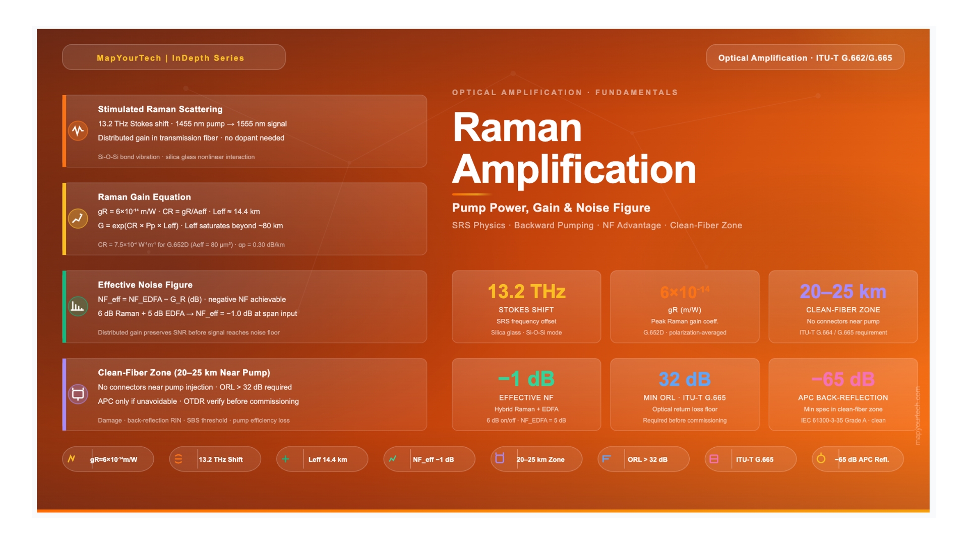
Raman Amplification Fundamentals: Pump Power, Gain, and Noise Figure
A practical guide to Raman gain physics, backward vs. forward pumping trade-offs, the effective noise figure advantage over EDFA, and design rules for ultra-long spans in deployed optical networks.
1. Introduction
"The fiber itself is the amplifier. When you pump it right, you turn every kilometer of glass into a gain medium. That changes the economics of long-haul completely."
— Robin Stolen, Bell Laboratories, on the first observation of stimulated Raman scattering in optical fiberEvery optical engineer working on long-haul or ultra-long-haul systems eventually confronts the same ceiling: Erbium-Doped Fiber Amplifiers (EDFAs) add noise at each amplification point, and as spans get longer or budgets tighter, the accumulated noise figure becomes the binding constraint on system reach. Raman amplification breaks that ceiling by distributing the gain along the transmission fiber itself, before signal power has fallen far enough to generate significant spontaneous emission noise.
The principle is rooted in stimulated Raman scattering (SRS), a nonlinear interaction in which pump photons transfer energy to signal photons through molecular vibrations in silica glass. The pump travels through the same fiber as the signal—typically in the opposite direction—and the signal experiences distributed amplification over tens of kilometers rather than a lumped gain event at a single point. This distinction is not academic: distributed gain preserves signal-to-noise ratio in a fundamentally different way than any lumped amplifier can.
As of 2026, Raman amplification appears in three distinct deployment contexts: as a pure distributed amplifier on ultra-long terrestrial routes, as an OSNR booster combined with EDFA in hybrid configurations, and as a low-noise front-end on coherent submarine systems. Each context demands a different balance of pump power, pumping direction, and gain target. This article covers the physics that govern all three, with enough quantitative detail to support real design decisions.
2. Physics of Stimulated Raman Scattering
2.1 The Molecular Vibration Mechanism
When a photon traveling through silica glass interacts with a Si-O-Si bond, it can excite the bond into a higher vibrational state and scatter inelastically. The scattered photon emerges at a lower energy (longer wavelength) than the incident photon, with the energy difference deposited into the vibrational mode. This is spontaneous Raman scattering, and at room temperature it occurs at a rate too low to be useful for amplification.
Stimulated Raman scattering occurs when a strong pump field is present at the fiber input. The pump photons coherently drive the molecular vibrations, and the scattered photons are produced not randomly but in phase with an existing signal at the Stokes-shifted wavelength. The signal field stimulates further scattering in its own direction, producing exponential gain. The pump photon is annihilated and a signal photon is created—a photon conversion process governed entirely by the fiber material, not by a dopant.
2.2 The Stokes Frequency Shift
Silica glass has a broad Raman gain spectrum centered approximately 13.2 THz below the pump frequency. This ~440 cm-1 shift corresponds to the dominant Si-O-Si stretching vibration. For a pump wavelength of 1455 nm, the Stokes shift places peak gain at approximately 1555 nm, squarely within the ITU-T C-band. A pump at 1366 nm shifts gain to the L-band center near 1480 nm. Operators choose pump wavelengths with precision to place the gain peak on the most loaded portion of the channel plan.
The Raman gain spectrum in silica is inherently broad—roughly 30 THz at the 10-dB points—which is both an advantage and a design factor. The broad spectrum means that a single pump wavelength amplifies all C-band channels simultaneously, but it also means gain is not flat across the band. Systems deploying more than 40 channels typically use two or more pump wavelengths to flatten the gain profile, a technique called multi-pump Raman amplification.
2.3 The Gain Coefficient
The peak Raman gain coefficient for standard single-mode fiber (ITU-T G.652) at the 13.2 THz shift is approximately gR = 6×10-14 m/W, accounting for random polarization states between pump and signal. This value is substantially lower than for crystalline Raman materials (silicon, for example, has gR roughly 104 times higher), which is why useful gain requires high pump powers and long interaction lengths. The effective gain coefficient normalized to fiber cross-section is:
Read the Full Analysis with Premium
The remaining 88% of this article — the design numbers, trade-offs and field guidance — is part of MapYourTech Premium, along with the full premium library, courses and professional tools.
You May Also Like

-
Free
-
September 4, 2026

-
Premium
-
September 4, 2026

-
Premium
-
September 4, 2026