
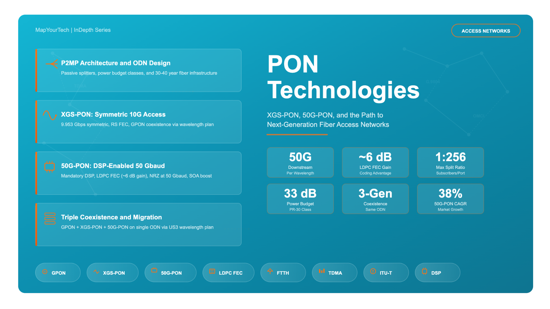

PON Technologies: XGS-PON, 50G-PON, and the Path to Next-Gen Access
A comprehensive engineering guide to passive optical network evolution, from GPON foundations through 50G-PON and beyond, covering architecture, physical layer design, wavelength planning, coexistence strategies, and deployment considerations.
1. Introduction
Passive Optical Networks (PONs) form the foundation of modern fiber-to-the-home (FTTH) and fiber-to-the-premises (FTTP) deployments worldwide. As of 2025, over 800 million FTTH/B connections exist globally, with PON technology serving as the dominant access architecture for fiber broadband. The evolution from Gigabit PON (GPON) to 10-Gigabit-capable XGS-PON, and now toward 50-Gigabit-capable 50G-PON, represents one of the most significant technology transitions in access networking history.
This transition is driven by exponential growth in bandwidth demand. Residential subscribers increasingly consume 8K video streaming, cloud gaming, extended reality (XR), and work-from-home applications that require symmetric multi-gigabit connectivity. Enterprise customers need low-latency, high-capacity links for cloud services and software-as-a-service platforms. Mobile network operators require high-bandwidth fronthaul and midhaul links for 5G and emerging 5G-Advanced radio access networks. All these demands converge on the optical access network, pushing operators to upgrade from the 2.5 Gbps shared capacity of GPON toward the 10 Gbps of XGS-PON and eventually the 50 Gbps of 50G-PON.
The unique challenge in PON evolution is that operators must upgrade capacity while preserving their investment in existing Optical Distribution Networks (ODNs). The ODN, consisting of optical fiber, passive splitters, and connectors, represents the most expensive and longest-lived component of a PON deployment, with expected lifetimes of 30 to 40 years. Any next-generation PON technology must operate over the same physical infrastructure, coexisting with earlier generations through careful wavelength planning and power budget engineering. This coexistence requirement has profoundly shaped the design of XGS-PON and 50G-PON, and understanding it is essential for network architects planning access network evolution.
This article provides a comprehensive technical examination of PON technology from its GPON foundations through XGS-PON and into the 50G-PON era. It covers the physical layer architecture, wavelength planning, optical power budgets, modulation and Digital Signal Processing (DSP) innovations, standards evolution, coexistence mechanisms, and real-world deployment considerations. The goal is to serve as a reference-grade resource for engineers, architects, and technology planners navigating the transition to next-generation optical access.
2. PON Architecture Fundamentals
2.1 Point-to-Multipoint Topology
A Passive Optical Network uses a point-to-multipoint (P2MP) topology where a single Optical Line Terminal (OLT) at the operator's central office communicates with multiple Optical Network Units (ONUs) or Optical Network Terminals (ONTs) at subscriber premises. The key defining characteristic of a PON is that the distribution network between the OLT and ONUs contains no active (powered) elements. All splitting and combining is performed by passive optical power splitters, which divide the downstream optical signal into multiple copies and combine upstream signals from multiple ONUs onto a single fiber.
The OLT serves as the network-side interface, connecting the access network to the metro/core network. It manages downstream broadcasting, upstream Time Division Multiple Access (TDMA) scheduling, Dynamic Bandwidth Allocation (DBA), ONU registration and authentication, and network management functions. The ONT/ONU serves as the customer-side interface, converting between optical signals on the PON side and electrical signals delivered to subscriber equipment via Ethernet, Wi-Fi, or other interfaces.
Figure 1: PON Point-to-Multipoint Architecture showing OLT, passive splitter, and multiple ONT/ONU types serving residential, enterprise, and mobile backhaul applications.
2.2 TDM Downstream and TDMA Upstream
In the downstream direction, the OLT continuously broadcasts data to all ONUs on the PON. The downstream signal is formatted into fixed-length 125 microsecond frames. Each frame contains a physical synchronization header and multiple data units addressed to specific ONUs. Every ONU receives the complete downstream frame but only processes the data addressed to it, discarding the rest. This is similar to an Ethernet broadcast domain, with addressing handled at the GEM (GPON Encapsulation Method) or XGEM frame level.
In the upstream direction, since all ONUs share a single fiber path through the passive splitter, a Time Division Multiple Access (TDMA) mechanism prevents signal collision. The OLT assigns each ONU a specific time slot within each 125 microsecond upstream frame. The ONU burst-transmits its data only during its assigned time slot. To ensure that upstream bursts from different ONUs arrive at the OLT without overlap despite varying fiber distances, a ranging process measures the round-trip delay to each ONU and assigns an equalization delay so that all bursts align correctly at the OLT receiver.
This burst-mode upstream transmission is one of the most technically demanding aspects of PON systems. The OLT receiver must handle bursts arriving with different optical power levels from different ONUs (due to varying path losses) and must rapidly re-synchronize its clock to each new burst. This requirement for burst-mode receivers becomes increasingly challenging at higher data rates, which is a key consideration in the design of 50G-PON systems.
Read the Full Analysis with Premium
The remaining 88% of this article — the design numbers, trade-offs and field guidance — is part of MapYourTech Premium, along with the full premium library, courses and professional tools.


