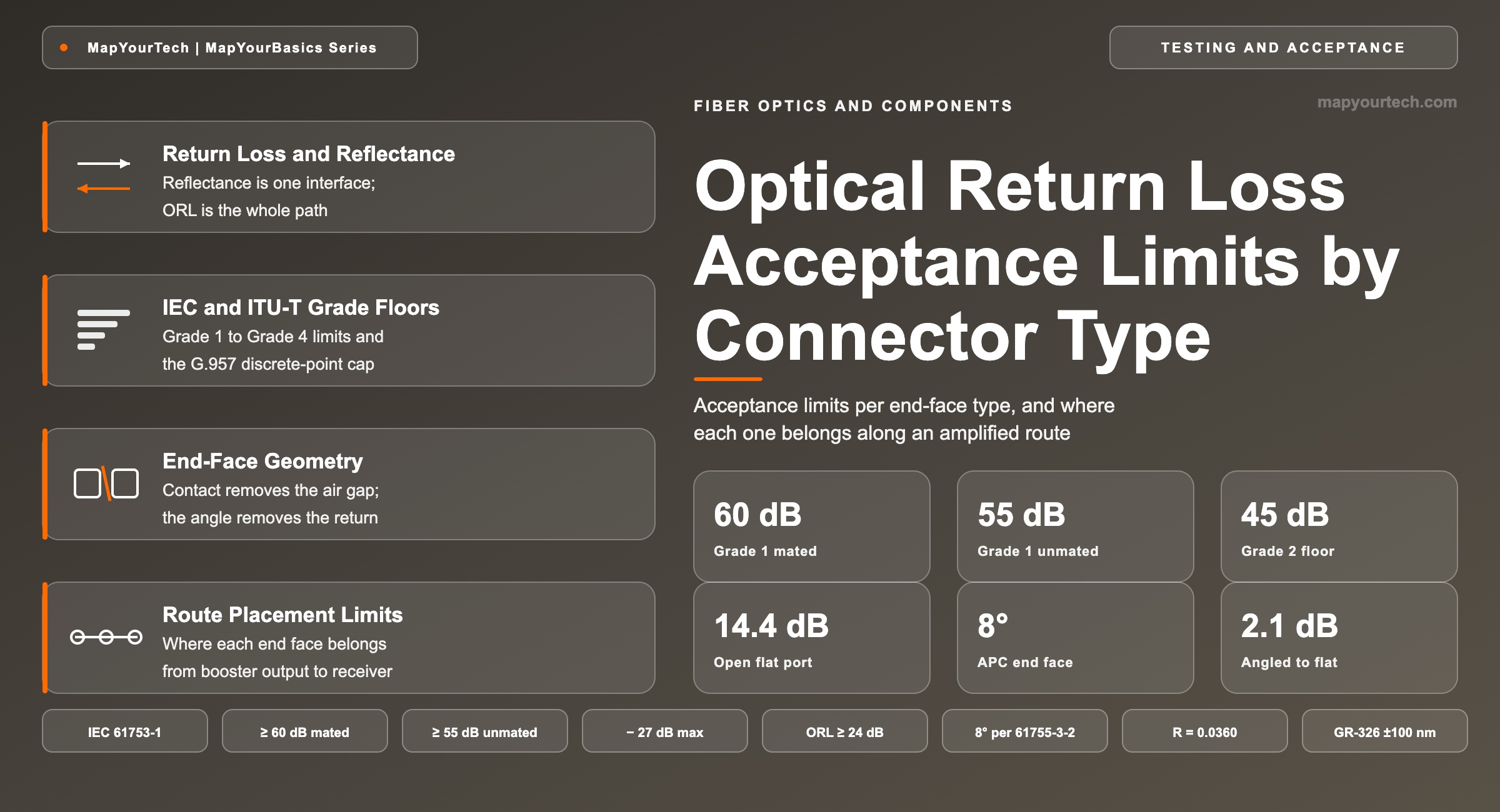
Optical Return Loss Acceptance Limits by Connector Type
The acceptance limit each end-face polish has to hold, where each type belongs in a route, and what an angled ferrule does when it meets a flat one.
A splice loss is permanent; a connector loss is a maintenance decision.
1. Introduction
A mated single-mode connector pair returns somewhere between one part in twenty-five and one part in a million of the power that reaches it, and the deciding factor is the shape of the two end faces rather than the brand on the housing. An open flat ferrule returns about 3.6 % of incident power, a figure fixed by the refractive index step from silica to air (theoretical limit). A well-made angled pair returns about 0.0001 %. Between those two numbers sit every acceptance limit an installer is asked to certify against and every reflection-driven fault a commissioning engineer has to explain.
The three polish families in single-mode telecom equipment are physical contact (PC), ultra physical contact (UPC) and angled physical contact (APC), and they sit roughly 20 dB apart in mated return loss. That spacing is not a manufacturing accident; each family removes a different part of the reflection mechanism, and the angled family removes the one that matters to a coherent receiver, a Raman pump and an analogue video carrier alike. This article states the acceptance limit for each type as the standards write it, derives the geometry behind the 20 dB steps, shows how per-pair reflectance accumulates into a link figure, places each type in a real route, and works through the case where an angled ferrule is mated to a flat one. Insertion loss is treated only where it interacts with reflection; the companion treatment of optical return loss against insertion loss covers the forward-direction budget in full, and connector loss budgets for SC, LC and MPO covers the ferrule formats.
2. Return Loss and Reflectance Definitions
Return loss is the ratio of the optical power incident on an interface to the optical power that interface sends back toward the source, expressed in decibels as a positive number. Reflectance describes the same physical event as a negative decibel value referred to the incident power. Optical return loss extends the measurement to a whole path, summing every discrete reflection and the distributed backscatter of the fiber.
2.1 Distinctions That Get Conflated
Three pairs of quantities carry different definitions and different acceptance limits, and mixing them is the most common source of a specification argument at handover. Reflectance against return loss: the same measurement with the sign flipped, so a pair specified at −60 dB reflectance and a pair specified at 60 dB return loss are identical, and a specification that mixes the two conventions in one table invites a 120 dB error. Reflectance against optical return loss: reflectance is a single-event property belonging to one connector, splice or component face, while optical return loss is a path property that adds every event plus Rayleigh backscatter, which is why a path built entirely of −60 dB pairs can still measure 35 dB of link ORL. Return loss against insertion loss: they fail independently, so a connector can pass a power-meter loss test and fail a reflectance test on the same mating, and contamination is the mechanism most likely to move one without the other.
2.2 Units and Conversion
One line converts between the linear fraction and the decibel form used in every acceptance table:
RL = −10 log10 R [dB] and reflectance (dB) = −RL
Where: R is the reflected power fraction, dimensionless, from 3.6 × 10⁻² at an open glass–air face down to 1 × 10⁻⁶ at a Grade 1 mated pair. RL is return loss in dB, positive, typically 14–70 dB for connector interfaces.
Worked instantiation, using the interface every other value is measured against: a flat silica end face against air reflects R = [(1.468 − 1.000)/(1.468 + 1.000)]2 = 0.0360 (theoretical limit, from the Fresnel coefficient at normal incidence). Converting, RL = −10 log10(0.0360) = 14.4 dB, and the reflectance is −14.4 dB. Every unmated flat port in a distribution frame sits at that value, and it recurs throughout this article as the reference case.
Takeaway: reflectance belongs to one interface and optical return loss belongs to a path. The acceptance limits in the next section are written against the first quantity; the turn-up measurement an operator records is usually the second, and the two only agree when a single reflection dominates the path.
3. Standards Basis for Connection Return Loss
Return loss grades for single-mode connectors are set by IEC 61753-1, which pairs a numbered return loss grade with a lettered attenuation grade so that a product is specified as, for example, Grade B1 or Grade C3. Four return loss grades are defined for single-mode connections, measured at 1310 nm, 1550 nm and 1625 nm, and only Grade 1 carries a separate unmated requirement.
| Grade | Mated return loss | Unmated return loss | End face that normally meets it |
|---|---|---|---|
| Grade 1 | ≥ 60 dB | ≥ 55 dB | Angled physical contact, 8° |
| Grade 2 | ≥ 45 dB | — | Ultra physical contact |
| Grade 3 | ≥ 35 dB | — | Physical contact |
| Grade 4 | ≥ 26 dB | — | Physical contact, relaxed class |
| Grade B | — | — | Attenuation ≤ 0.12 dB mean, ≤ 0.25 dB for ≥ 97 % of matings |
| Grade C | — | — | Attenuation ≤ 0.25 dB mean, ≤ 0.50 dB for ≥ 97 % of matings |
Two other bodies bound the same parameter from the system side rather than the component side. ITU-T G.957 caps the reflectance of any single discrete point between the source and receive reference points at −27 dB and sets a minimum path optical return loss of 24 dB for general terrestrial applications (standard-specified), with 14 dB permitted on specific relaxed interface configurations. ITU-T G.671 carries the component-level reflectance tables and states the convention explicitly: components are specified in reflectance as a negative number, systems in return loss as a positive one. In structured cabling, the TIA-568 series has set a floor of 26 dB for single-mode connections and splices and 20 dB for multimode, with 55 dB required for broadband analogue video service (standard-specified) — a reminder that an analogue carrier needs an order of magnitude better reflection control than a digital one at the same bit rate.
Telcordia GR-326-CORE approaches the problem from geometry instead of from optics. It qualifies single-mode connectors and jumper assemblies against end-face parameters that a return loss measurement only reports indirectly: radius of curvature, apex offset, fiber height and angular offset, with the angled class held to 7.5°–8.5° and fiber height held within ±100 nm of the ferrule surface (standard-specified). Those four numbers are what a supplier's interferometer report contains, and they predict whether a connector will still meet its return loss grade after a few hundred mating cycles. A supplier that publishes GR-326 interferometry alongside an IEC grade is describing the same connector twice, once by outcome and once by cause. The optical specifications reference collects the related component limits in one place.
Takeaway: IEC 61753-1 fixes what one mated pair must return, ITU-T G.957 fixes what the whole path must return, and GR-326 fixes the end-face geometry that keeps the first number true over service life. An acceptance document that cites only one of the three leaves a gap somebody will find at turn-up.
4. End-Face Geometry and the Reflection Mechanism
Reflection at a connector has two independent causes, and each polish family attacks one of them. The first is the Fresnel step at a glass–air boundary, worth −14.4 dB whenever a gap of any width separates two end faces. The second is the return path: even a small reflection matters only if the reflected field couples back into the guided mode travelling toward the source.
PC polish attacks the first cause. A convex dome of roughly 25 mm radius of curvature puts the two fiber cores in contact at the apex under spring load, so no air gap remains at the core and the glass–air step disappears. What survives is scattering from residual surface roughness and from the compressed glass at the contact point, which is why PC connections settle around 40 dB of mated return loss in practice (measured, typical field value) against the 35 dB Grade 3 floor. UPC polish attacks the same cause harder: a finer abrasive sequence and tighter radius control reduce sub-surface damage and surface roughness, lifting typical mated return loss to around 50 dB (measured, typical field value) against the 45 dB Grade 2 floor. Neither changes the return path, so whatever does reflect goes straight back down the core.
APC polish attacks the second cause and inherits the benefit of the first. Tilting the end face by 8° means a ray reflecting from that face leaves at twice the tilt, 16° to the fiber axis. The guided mode of G.652 fiber at 1550 nm has an angular half-width of about 3.7° inside the glass, calculated as λ/(πnw) with a mode field radius of 5.2 µm, so a 16° ray is more than four times outside it. Evaluating the Gaussian-mode overlap integral at that tilt gives about 81 dB of coupling suppression (theoretical limit, computed from the Marcuse angular-misalignment expression). The angle, not the polish quality, is what sets the Grade 1 floor, and it is also why an unmated angled port still returns 55 dB or better while an unmated flat port returns 14 dB.
Physical contact removes the glass–air boundary; the angle removes the return path. A design that needs 60 dB has to have both, which is why no amount of polishing quality lifts a flat ferrule into Grade 1 and why an angled ferrule that has lost physical contact still holds its grade.
Takeaway: the 20 dB steps between PC, UPC and APC come from two different mechanisms, not from three levels of the same one. PC to UPC buys better surface quality; UPC to APC buys a geometry that stops the reflection from being recaptured at all.
5. Link Return Loss Accumulation
Reflections add in linear power, not in decibels, so a path figure is built by converting every reflectance to a fraction, summing, and converting back. The Rayleigh backscatter of the fiber itself enters the same sum as a distributed term that a long span cannot get below.
ORL = −10 log10 ( Σ Ri + RRayleigh ) [dB]
Where: Ri is the linear reflectance of the i-th discrete event, dimensionless, typically 1 × 10⁻⁶ (Grade 1) to 2.5 × 10⁻³ (Grade 4). RRayleigh is the accumulated backscatter fraction of the fiber, typically 3 × 10⁻⁴ to 1 × 10⁻⁴ for spans of 40–100 km of G.652 fiber at 1550 nm. ORL is path optical return loss in dB, higher meaning less returned power. The expression neglects the forward and return attenuation to each event, which makes it the worst case.
Take a six-pair path built entirely from Grade 1 angled connections at −60 dB each. The discrete sum is 6 × 10−6 = 6.0 × 10⁻⁶, giving 52.2 dB of discrete-only ORL. Add an 80 km span whose Rayleigh floor is 35 dB, worth 3.16 × 10⁻⁴, and the total drops to 34.9 dB. Nothing is wrong with the connectors; the fiber is simply returning fifty times more power than they are. Now replace one of those pairs with a contaminated flat pair measuring −30 dB. The discrete sum becomes 1.005 × 10⁻³, discrete-only ORL falls to 30.0 dB, and that one interface now accounts for 99.5 % of the connector-generated return. The arithmetic is what makes the acceptance limit a per-pair number rather than an average.
Takeaway: path return loss is set by the worst single interface, not by the average of the good ones. One degraded pair at −30 dB overwhelms five pairs at −60 dB by a factor of two hundred, so acceptance testing has to be per-connector and per-event, which is what an OTDR trace reader reports directly.
6. Acceptance Limits and Route Placement
Acceptance limits differ by position in the route because the consequence of a reflection differs. A reflection near a high-power output couples more absolute power backward; a reflection near a narrow-linewidth source couples into a cavity that responds to it; a reflection between two other reflections creates a delayed interfering copy of the signal at the receiver.
| Route position | End face | Per-pair limit | Binding mechanism |
|---|---|---|---|
| Booster output to first span | APC | ≥ 60 dB | Highest absolute reflected power in the route; reflection returns into the amplifier output stage |
| Raman pump injection point | APC | ≥ 60 dB | Pump units rated 1.5–5 W (vendor specification); a reflective interface converts pump power into a damage and multipath risk |
| ROADM and terminal patch field | APC | ≥ 60 dB | Many mated pairs in series; each one adds to the same linear sum |
| Coherent transceiver client port | UPC or APC per module | ≥ 45 dB | Module specification governs; narrow-linewidth sources respond to feedback |
| Grey client and short data centre link | UPC | ≥ 45 dB | Short path, few pairs, direct detection tolerant of the residual return |
| Analogue video or RF over fiber | APC | ≥ 55 dB | Interferometric intensity noise appears directly as distortion in the recovered carrier |
| Unused port on a live frame | APC with dust cap | ≥ 55 dB | An unmated flat port returns 14.4 dB and can dominate the whole path |
The Raman row deserves its number rather than a general caution. Counter-propagating pump units in commercial line systems are specified at 1.5 W to 5 W of launched pump power (vendor specification), against per-channel signal powers of a few milliwatts. A flat interface anywhere in the first few kilometres of that fiber sees pump power measured in watts, returns a percent of it toward the pump module, and does so at a point where the fiber is carrying the highest optical intensity in the whole route. Vendor commissioning guidance for high-power Raman line systems is consistent on the point: clean every connector in the pump path carefully, because reflection close to the terminal both degrades signal quality through multipath interference and puts the connector and the pump module at risk. On those routes the acceptance limit stops being a quality target and becomes an equipment protection requirement. The DWDM commissioning checklist and the troubleshooting guide both place connector inspection ahead of power measurement for this reason.
Two further placement rules follow from the same arithmetic. A cross-connect path through a carrier-neutral facility can accumulate six or more mated pairs before it reaches either end system, and every one of them lands in the linear sum, which is why meet-me-room handoff specifications name the end-face type explicitly rather than leaving it to the installing party. And an unused angled port in a live frame is safe to leave dark at 55 dB or better, while an unused flat port at 14.4 dB can single-handedly set the return loss of any path that shares its splitter or coupler.
Takeaway: angled end faces are the default everywhere the route carries amplified or pumped power, everywhere a narrow-linewidth source is present, and everywhere a patch field puts several pairs in series. Flat end faces remain a reasonable choice on short, lightly connectorised, direct-detection paths, and nowhere else in a long-haul route.
7. Angled-to-Flat Mating Analysis
Mating an angled ferrule to a flat one fails both parameters at once, and the two failures have separate causes worth separating. The insertion loss failure comes from refraction. Light leaving the 8° face into the air gap refracts to 11.79° from the face normal by Snell's law, which is 3.79° away from the ferrule axis. Entering the flat receiving face at normal incidence it refracts back to a 2.58° tilt inside the receiving fiber. Evaluating the Gaussian-mode overlap at that tilt gives 2.1 dB of coupling loss (theoretical limit) before any gap or offset term is counted, and the walk-off across the gap adds a lateral offset that grows with gap width.
The return loss failure comes from the gap itself. An angled apex cannot make physical contact with a flat face, so a glass–air boundary remains on both sides of the joint. The flat face reflects at close to normal incidence and returns that reflection into its own core, so the flat side of the pairing measures near the open-port value of 14.4 dB rather than its rated 45 or 50 dB. A path that was designed at 60 dB per pair now contains one interface at roughly 14 dB, and by the linear sum of Section 5 that single interface sets the entire path figure at about 14 dB regardless of what the other pairs achieve.
The mechanical consequence is the reason the industry colour-codes the two families rather than relying on measurement to catch the mistake. The angled apex bears against a flat surface under full spring load, concentrating the contact force on a small area of the angled fiber and the mating ferrule. Green housings and green adapters for angled, blue for flat single-mode, are the convention that keeps the two apart, and a keyed adapter that refuses to seat is the convention working as intended rather than a defective part. If a green connector does not seat cleanly in a blue adapter, that is the design preventing an unrecoverable pair of failures.
Takeaway: an angled-to-flat mating costs about 2 dB of insertion loss from refraction and collapses return loss to roughly the open-port value of 14 dB, and it risks permanent end-face damage on both ferrules. The colour code exists because the optical result is not always obvious on a power meter, while the return loss result always is.
8. Conclusion
Four numbers cover most acceptance decisions. Grade 1 angled connections hold 60 dB mated and 55 dB unmated; Grade 2 holds 45 dB; Grade 3 holds 35 dB; Grade 4 holds 26 dB. Above those, ITU-T G.957 caps any single discrete reflection at −27 dB and sets 24 dB as the minimum path optical return loss for general terrestrial service, while a coherent turn-up is normally verified at 45 dB or better on the discrete contribution. Below them, GR-326 end-face geometry decides whether a connector still meets its grade after the hundredth mating.
Two structural facts govern how those numbers are applied. Reflections sum in linear power, so the worst interface sets the path figure and averaging hides the fault. And the angle, not the polish, is what buys the last 20 dB, which is why an angled end face is the default anywhere the route carries amplified power, pumped power, a narrow-linewidth source, or more than a couple of mated pairs in series. Where a specification has to be written in one line, it is worth writing all three parts: the IEC grade for the component, the ITU-T path limit for the system, and an end-face inspection criterion for the condition the component is actually in when it is measured. Definitions for the terms used throughout are collected in the optical glossary, and the forward-direction arithmetic is available in the link attenuation calculator.
References
- IEC 61753-1 — Fibre optic interconnecting devices and passive components — Performance standard — Part 1: General and guidance, International Electrotechnical Commission.
- IEC 61300-3-6 — Fibre optic interconnecting devices and passive components — Basic test and measurement procedures — Part 3-6: Examinations and measurements — Return loss, International Electrotechnical Commission.
- IEC 61755-3-2 — Fibre optic connector optical interfaces — Part 3-2: Optical interface for single mode fibres with angled physical contact connectors, International Electrotechnical Commission.
- IEC 61300-3-35 — Fibre optic interconnecting devices and passive components — Basic test and measurement procedures — Part 3-35: Examinations and measurements — Visual inspection of fibre optic connectors and fibre-stub transceivers, International Electrotechnical Commission.
- ITU-T Recommendation G.671 — Transmission characteristics of optical components and subsystems, ITU-T Study Group 15.
- ITU-T Recommendation G.957 — Optical interfaces for equipments and systems relating to the synchronous digital hierarchy, ITU-T Study Group 15.
- Telcordia GR-326-CORE — Generic Requirements for Single-Mode Optical Connectors and Jumper Assemblies, Telcordia Technologies.
- ANSI/TIA-568.3 series — Optical Fiber Cabling and Components Standard, Telecommunications Industry Association.
- D. Marcuse, Loss analysis of single-mode fiber splices, Bell System Technical Journal.
Related Articles on MapYourTech