
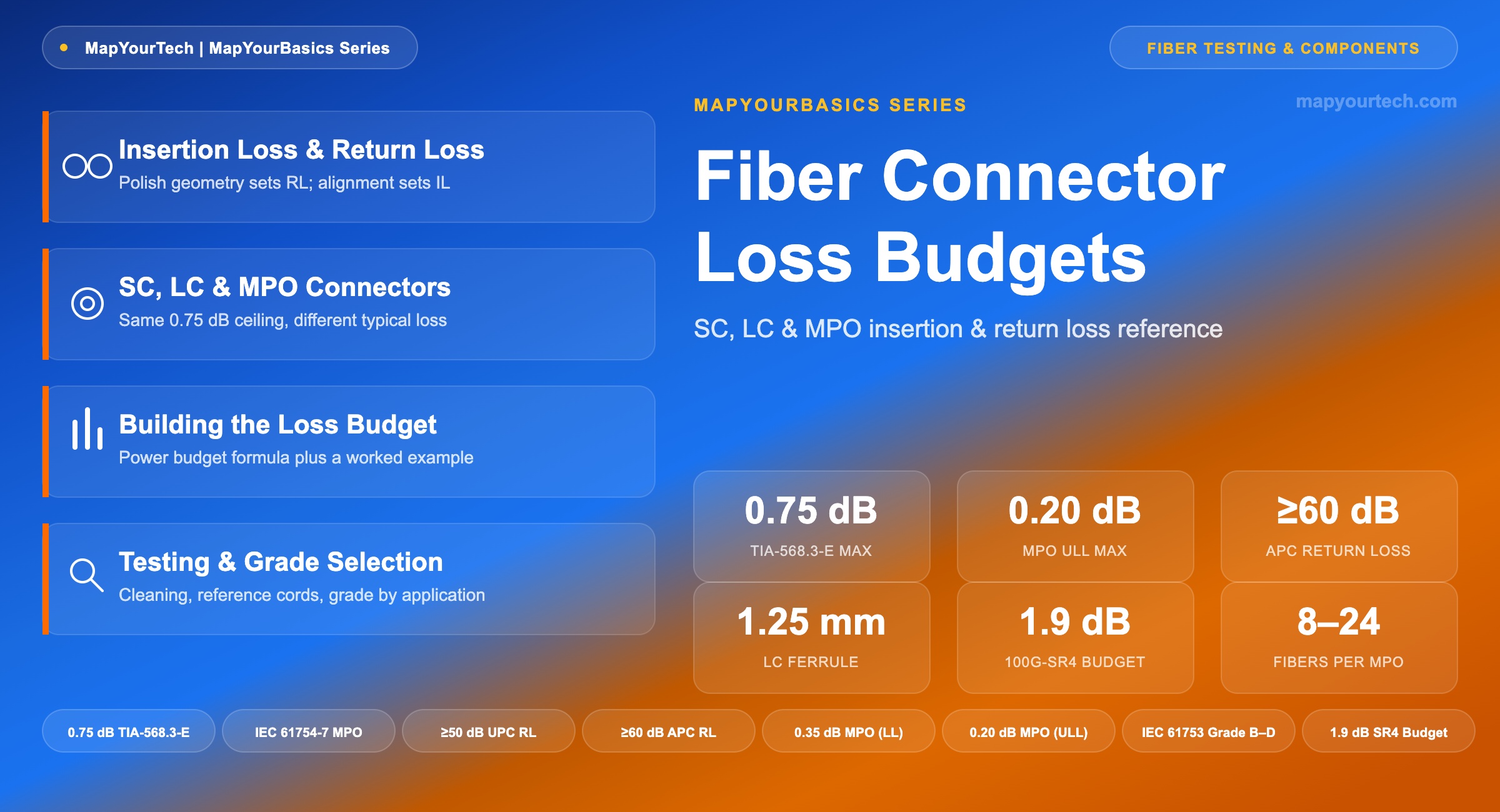
Fiber Connector Loss Budgets: SC, LC, and MPO
A field reference for the insertion-loss and return-loss allowances that SC, LC, and MPO connectors carry into a fiber link — with standard-grade ceilings, typical achieved performance, and a worked design example.
1. Introduction
A single mated connector pair removes somewhere between roughly 0.15 dB and 0.75 dB from a fiber link, depending on connector grade, polish type, and end-face cleanliness. On its own that number barely registers next to fiber attenuation or amplifier gain. Stack four or five connector pairs along the same path — a patch cord at the transmitter, a cross-connect at the main distribution frame, an MPO trunk into a cassette, a patch cord at the receiver — and the total starts to compete with the fiber loss itself, especially on short links where fiber attenuation contributes very little to begin with.
This reference covers the three connector families an optical engineer meets daily: SC (Subscriber Connector), LC (Lucent Connector), and MPO (Multi-Fiber Push-On). Each carries a published standard-grade loss ceiling, a typical achieved performance range that is considerably tighter than that ceiling, and application-specific return-loss requirements driven by how sensitive the attached laser or receiver is to reflected light. The stakes for getting this right have grown with connector count rather than shrunk: at 800 Gb/s and 1.6 Tb/s parallel-optic rates, the per-lane channel insertion-loss allowance is measured in single-digit decibels, and a connector grade that was an acceptable rounding error at 1 Gb/s can now consume a third of the entire budget.
The goal here is practical rather than exhaustive: know what each connector type actually costs a link in decibels, know which number applies to design (the standard ceiling) versus which applies to a healthy, well-terminated plant (the typical figure), and know how to build those numbers into a power budget calculation that either passes or fails before the fiber ever goes in the ground.
2. Insertion Loss, Return Loss, and Polish Type
Insertion loss (IL) is the reduction in optical power caused by inserting a component — here, a mated connector pair — into an otherwise continuous fiber path. It is expressed in decibels as the ratio of output power to input power, and every value quoted in this article is a mated-pair figure: the loss contributed by two connectors pushed together, not a single unmated ferrule. The physical mechanisms behind that loss are the same ones that govern any fiber joint — transverse core offset, angular misalignment, an air gap between end faces, and mode-field diameter mismatch — and are covered in more depth in the MapYourTech piece on optical return loss versus insertion loss.
Return loss (RL), sometimes tracked at the system level as optical return loss (ORL), measures how much of the launched power reflects back toward the source at the connector interface. Polish geometry sets the ceiling on this number. A Ultra Physical Contact (UPC) connector uses a flat, slightly domed polish and typically achieves 50 dB or better return loss (a widely reported vendor and field-measurement range). An Angled Physical Contact (APC) connector cuts the ferrule end-face at an 8° angle, which redirects reflected light into the fiber cladding instead of back down the core; the mechanism routinely pushes return loss above 60 dB, and the 2025 revision of IEC 61754-20 tightens the minimum requirement for SC/APC connectors used in FTTH passive optical networks specifically to 65 dB (standard-specified). The deeper physics of why return loss matters — laser instability, relative intensity noise, and the Rayleigh-backscatter floor that ultimately limits any span — is covered in the MapYourTech guide to understanding optical return loss.
Never mate a UPC connector to an APC connector. The angled and flat end-faces do not make physical contact correctly; the result is high insertion loss, poor return loss, and permanent scratching of the angled ferrule. Color coding exists precisely to prevent this: blue housings and boots indicate UPC/PC polish, green indicates APC. Always mate blue-to-blue or green-to-green.
International standard IEC 61753 formalizes connector performance into attenuation grades rather than leaving "typical" undefined. Grade B allows a maximum of 0.25 dB at the 97th percentile with a 0.12 dB mean; Grade C allows 0.50 dB maximum with a 0.25 dB mean; Grade D allows 1.0 dB maximum with a 0.50 dB mean (standard-specified, IEC 61753). These grades are the technical basis behind the marketing terms "low-loss" and "premium" that vendors attach to patch cords and trunk assemblies — a connector advertised as low-loss is, in effect, claiming Grade B performance, while a standard commodity part is closer to Grade C or D.
Takeaway: Insertion loss and return loss are independent parameters governed by different physical mechanisms — core alignment for insertion loss, end-face angle for return loss — and a connector spec sheet that quotes only one of the two is telling half the story. Match polish types, and treat the IEC 61753 grade letter as the real specification hiding behind a "low-loss" label.
3. SC, LC, and MPO: Three Connector Families
All three connector types share the same standard-grade insertion-loss ceiling for a mated pair under TIA-568.3-E, the current edition of the premises optical fiber cabling standard published by the Telecommunications Industry Association's TR-42.11 subcommittee: 0.75 dB maximum (standard-specified). What separates the three families in practice is how far below that ceiling a well-made, clean connection typically lands — and, for MPO specifically, how many fibers are riding on a single mated pair when that loss is applied.
3.1 SC — Subscriber Connector
The SC connector uses a 2.5 mm ceramic ferrule and a push-pull latching body — no twist, no bayonet, just a straight push to mate and a straight pull to release. That mechanical simplicity, combined with a square cross-section that packs reasonably densely on a patch panel, made it the dominant telecom and premises connector through the 1990s and 2000s. It still holds that position in outside-plant enclosures and optical distribution frames, where its larger ferrule and generous mating-cycle rating (500 mating cycles minimum under IEC 61753-1, standard-specified) suit equipment that gets serviced infrequently but roughly. SC/APC is the default connector on the vast majority of GPON and EPON optical network terminals, because passive optical network upstream receivers operate in burst mode and are unusually sensitive to back-reflected light from downstream connectors.
3.2 LC — Lucent Connector
The LC connector shrinks the ferrule to 1.25 mm — half the diameter of SC — which doubles the port density achievable in the same panel width. That density gain is the entire reason LC became the standard interface on SFP, SFP+, QSFP, and every pluggable transceiver family that followed: a faceplate that could hold 24 SC ports holds roughly 48 LC ports. LC shares the same 0.75 dB TIA-568.3-E standard-grade ceiling as SC, but production LC assemblies from established manufacturers routinely land in the 0.15–0.25 dB range in typical, well-terminated practice — tighter alignment tolerances on a smaller ferrule tend to produce more consistent physical contact once manufacturing quality is controlled. LC/UPC dominates Ethernet client-side optics; LC/APC shows up wherever back-reflection tolerance is tight, most notably on DWDM add/drop ports feeding a reconfigurable optical add-drop multiplexer (ROADM) or on coherent transceiver line-side interfaces, where reflected light can destabilize a narrow-linewidth laser.
3.3 MPO — Multi-Fiber Push-On
MPO houses an entire row of fibers — commonly 8, 12, 16, or 24 — inside a single rectangular MT (mechanical transfer) ferrule, aligned by a pair of precision guide pins rather than by an individually polished round ferrule per fiber. The mechanical interface is standardized by IEC 61754-7, with the companion connector-intermateability specification carried in TIA-604-5 (FOCIS-5), so MPO connectors from different manufacturers mate correctly by design. The same 0.75 dB standard-grade ceiling that industry link-budget guidance applies to duplex connectors is commonly referenced for MPO mated pairs as well, but the commercial market differentiates MPO far more sharply than it does SC or LC: a Low-Loss (LL) grade guarantees 0.35 dB maximum, and an Ultra-Low-Loss (ULL) grade guarantees 0.20 dB maximum (vendor-published grades, consistent across multiple connector manufacturers).
That grade spread matters more for MPO than for any duplex connector because of two compounding factors. First, MPO connectors carry proportionally more mating surfaces per footprint — a 12-fiber MPO packs twelve opportunities for endface contamination into the space of a single connector, and industry contamination studies attribute roughly 80% of fiber network problems to dirty connectors specifically because of this multiplication (industry measurement, widely cited from NTT-Advanced Technology testing). Second, MPO connectors sit almost exclusively on parallel-optic links — 100GBASE-SR4, 400GBASE-SR8/DR4, and the emerging 800G and 1.6T generations — where the per-lane channel insertion-loss budget is tight to begin with. Section 4 below works through exactly how tight. Fiber counts are also climbing: 2026 data center and AI-cluster deployments increasingly specify MPO-16 for 800G SR8/DR8 and trunk cables scaling to 144, 288, and even 432 fibers for the largest AI fabrics (current industry deployment pattern, 2026).
| Connector | Ferrule / Fiber Count | Standard-Grade Max IL | Typical / Low-Loss Grade IL | Return Loss (UPC) | Return Loss (APC) | Primary Application |
|---|---|---|---|---|---|---|
| SC | 2.5 mm ceramic, 1 fiber | 0.75 dB | 0.20–0.30 dB | ≥50 dB | ≥60 dB (≥65 dB FTTH*) | PON drops, legacy ODFs |
| LC | 1.25 mm ceramic, 1 fiber | 0.75 dB | 0.15–0.25 dB | ≥50 dB | ≥60 dB | Pluggable transceivers, DWDM add/drop |
| MPO | MT ferrule, 8/12/16/24 fibers | 0.75 dB | 0.35 dB (LL) / 0.20 dB (ULL) | ≥20 dB (MM) | APC grade available (SM) | 400G/800G parallel trunks |
*Per the 2025 revision of IEC 61754-20, minimum return loss for SC/APC connectors in FTTH PON deployments specifically.
Takeaway: SC, LC, and MPO all answer to the same 0.75 dB TIA-568.3-E ceiling, but they are not interchangeable in practice. LC wins on density and typical performance for duplex links; MPO wins on fiber count per mating cycle but demands an explicit low-loss or ultra-low-loss grade specification the moment it lands on a parallel-optic link with a tight channel budget.
4. Building a Loss Budget
A link budget calculation is the discipline of proving, before installation, that the power arriving at the receiver will exceed its sensitivity threshold by a comfortable margin. The building blocks are the transmitter's launch power, the receiver's sensitivity, and every source of loss standing between them — fiber attenuation, connector pairs, fusion splices, and a design margin held in reserve for aging, temperature drift, and future repairs. The full mechanics of power budget and rise-time budget calculations are covered at length in the MapYourTech article on optical network system design considerations; this section applies that framework specifically to connector loss.
Link Loss Budget
L_total = (α × L) + (N_conn × IL_conn) + (N_splice × IL_splice) + M
Link passes when L_total ≤ P_budget
Practical Example — A Short Single-Mode Client Link
Assume a representative single-mode client interface with 0 dBm launch power and −20 dBm receiver sensitivity — an illustrative range only, not tied to a specific transceiver, since actual figures vary by data rate and reach class and must come from the module's own data sheet. That gives a power budget of 20 dB. The link runs 2 km at 1310 nm through two LC/UPC connector pairs (one patch cord at each end) and two fusion splices at intermediate closures.
| Loss Element | Basis | Value |
|---|---|---|
| Fiber attenuation | 2 km × 0.35 dB/km (typical G.652 operational value at 1310 nm) | 0.70 dB |
| Connector pairs | 2 × 0.75 dB (TIA-568.3-E standard-grade ceiling, worst case) | 1.50 dB |
| Fusion splices | 2 × 0.10 dB (typical fusion splice, within ITU-T G.671 max of 0.3 dB) | 0.20 dB |
| Design margin | Aging, repair, temperature (industry-typical allowance) | 3.00 dB |
| Total required | 5.40 dB | |
| Available budget | 0 dBm − (−20 dBm) | 20.00 dB |
| Remaining margin | 14.60 dB — Pass |
Even evaluated at the pessimistic TIA-568.3-E standard-grade connector ceiling, this short link clears its power budget with more than 14 dB to spare. That headroom is exactly why connector grade rarely matters on short, lightly-connectorized single-mode links — the number that decides pass or fail is usually fiber length or amplifier spacing, not connector loss.
The picture changes on a parallel-optic MPO link, where the entire channel insertion-loss allowance is far smaller. TIA-568.3-D references roughly 1.9 dB of total channel insertion loss for a 100 m, 100GBASE-SR4 link over OM4 multimode fiber (standard-specified). A design using two standard-grade MPO-12 mated pairs — one at each end's patch panel — already consumes 2 × 0.75 dB = 1.50 dB, or 79% of the entire budget, before the fiber itself is counted, leaving under 0.4 dB for 100 m of fiber and any additional patch cords. Specifying low-loss (≤0.35 dB) MPO connectors instead drops that same two-pair consumption to 0.70 dB, freeing roughly 0.8 dB of additional headroom — the margin that separates a link that passes acceptance testing comfortably from one that fails intermittently as connectors age and accumulate minor contamination.
Takeaway: Connector grade is a design variable, not a fixed cost. On a short single-mode link with a generous power budget, the standard-grade ceiling is harmless. On a parallel-optic MPO link with a channel budget under 2 dB, the same ceiling can consume the majority of the available margin — which is precisely why low-loss and ultra-low-loss MPO grades exist as a procurement specification, not a marketing upgrade.
5. Testing and Grade Selection in Practice
Cleanliness dominates real-world connector performance more than any spec sheet grade. A single sub-micron particle lodged in a guide-pin hole or across a fiber core can add several decibels of loss on its own — enough to fail a link that was designed with comfortable margin on paper. The "inspect before you connect" discipline (visual inspection with a fiberscope before every mating cycle, per the pattern documented in the MapYourTech guide to optical time-domain reflectometry for locating problem events after the fact) remains the single highest-value habit in fiber plant maintenance.
Field verification of the insertion-loss numbers in this article relies on reference-grade test cords and the one-cord, two-cord, or three-cord reference methods defined in TIA-526-7 (single-mode) and TIA-526-14 (multimode); an optical loss test set (OLTS) or light-source-and-power-meter pair delivers Tier 1 certification, while an OTDR adds spatial resolution — showing exactly where along the span each decibel of loss occurs, a distinction covered in the MapYourTech piece on reading an OTDR trace. MPO links deserve a dedicated MPO-native test interface rather than a fan-out adapter down to individual LC strands; fanning out for testing introduces its own adapter loss and makes it easy to mis-map polarity across a 12- or 24-fiber connector.
Grade selection follows the application, not a blanket default:
- FTTH/PON drops: SC/APC or LC/APC, standard grade is normally sufficient — return-loss discipline matters more than insertion-loss grade here, because burst-mode upstream receivers are reflection-sensitive.
- Enterprise and campus LAN: LC/UPC at standard grade; most structured-cabling links carry enough margin that the 0.75 dB ceiling never becomes the limiting factor.
- Data center parallel optics (SR4/SR8/DR4/DR8): specify low-loss or ultra-low-loss MPO explicitly in the procurement documents; do not accept "typical" figures on a data sheet without a guaranteed maximum, a practice increasingly written into 2026 hyperscale procurement specifications.
- DWDM and coherent line-side ports: APC without exception, because even small reflections degrade OSNR and can destabilize a narrow-linewidth laser — a failure mode explored further in the MapYourTech analysis of the clean-fiber zone in Raman-amplified links and in the broader DWDM system commissioning checklist.
Takeaway: A clean, correctly polished standard-grade connector routinely outperforms a dirty premium one. Testing discipline — inspection before mating, reference-grade test cords, and connector-native test interfaces for MPO — protects the loss budget more reliably than any grade upgrade on its own.
Summary
SC, LC, and MPO connectors all sit under the same 0.75 dB TIA-568.3-E standard-grade ceiling, but that shared number is a worst-case design input, not a description of how a well-built connector actually performs. LC's smaller ferrule and tighter typical tolerances made it the natural fit for dense pluggable-transceiver faceplates; SC's mechanical simplicity kept it dominant in outside-plant and PON deployments where APC return-loss discipline matters more than raw density; MPO's ability to carry 8 to 24 fibers through a single mating cycle made it the only practical interface for parallel optics, at the cost of a per-lane budget tight enough that connector grade becomes a first-order design decision rather than an afterthought. As per-lane speeds and connector counts keep climbing toward 1.6 Tb/s and beyond, that last point is the one worth carrying forward: connector loss discipline is shifting from a line item buried in a test report to a hard gating criterion written directly into the procurement specification.
References
- Telecommunications Industry Association, TIA-568.3-E — Optical Fiber Cabling and Components Standard, TR-42.11 Optical Fiber Systems Subcommittee.
- International Electrotechnical Commission, IEC 61753 — Fibre Optic Interconnecting Devices and Passive Components: Performance Standard.
- International Electrotechnical Commission, IEC 61754-7 — Fibre Optic Connector Interfaces, Part 7: Type MPO Connector Family.
- ITU-T Recommendation G.671 — Transmission Characteristics of Optical Components and Subsystems, ITU-T Study Group 15.
- Sanjay Yadav, "Optical Network Communications: An Engineer's Perspective" — Bridge the Gap Between Theory and Practice in Optical Networking.
Related Articles on MapYourTech






