
Regulatory Compliance in Optical Transceivers
Comprehensive Guide to RoHS, Laser Safety, EMI/EMC Standards, and International Certification Requirements for Optical Network Components
Introduction
Optical transceivers are critical components in modern telecommunications infrastructure, enabling high-speed data transmission across fiber optic networks. As these devices become increasingly prevalent in data centers, enterprise networks, and service provider deployments, they must comply with a complex landscape of international regulatory standards. These regulations ensure environmental protection, operator safety, electromagnetic compatibility, and reliable operation in diverse deployment scenarios.
Regulatory compliance for optical transceivers encompasses multiple domains: environmental regulations that restrict hazardous substances, laser safety standards that protect technicians and operators from optical radiation, electromagnetic compatibility requirements that prevent interference with other equipment, and electrical safety standards that ensure reliable operation. Manufacturers must navigate this regulatory framework across different geographic regions, each with its own certification requirements and enforcement mechanisms.
This comprehensive guide examines the primary regulatory frameworks governing optical transceivers, including the European Union's Restriction of Hazardous Substances (RoHS) directive, international laser safety classifications under IEC 60825 and FDA regulations, electromagnetic interference and compatibility standards from FCC and CISPR, and various electrical safety and electrostatic discharge protection requirements. Understanding these standards is essential for network engineers specifying equipment, procurement professionals evaluating vendors, and compliance officers ensuring regulatory adherence.
1. RoHS Compliance: Restriction of Hazardous Substances
1.1 RoHS Directive Overview
The Restriction of Hazardous Substances (RoHS) Directive, officially known as Directive 2002/95/EC and later updated as Directive 2011/65/EU (RoHS 2) and Directive 2015/863/EU (RoHS 3), represents one of the most significant environmental regulations affecting optical transceiver manufacturing. Originally implemented by the European Union, RoHS has become a de facto global standard, influencing manufacturing practices worldwide and establishing requirements for similar regulations in other jurisdictions including China RoHS, Korea RoHS, and various state-level regulations in the United States.
The primary objective of RoHS is to restrict the use of specific hazardous materials found in electrical and electronic equipment, thereby reducing the environmental impact of electronic waste and protecting human health. For optical transceivers, which contain various electronic components, circuit boards, and optical assemblies, achieving RoHS compliance requires careful material selection throughout the supply chain and rigorous testing and documentation procedures.
Key RoHS Requirements for Optical Transceivers
RoHS limits the concentration of six restricted substances to maximum levels in homogeneous materials:
- Lead (Pb): Maximum 0.1% by weight (1000 ppm)
- Mercury (Hg): Maximum 0.1% by weight (1000 ppm)
- Cadmium (Cd): Maximum 0.01% by weight (100 ppm)
- Hexavalent Chromium (Cr6+): Maximum 0.1% by weight (1000 ppm)
- Polybrominated Biphenyls (PBB): Maximum 0.1% by weight (1000 ppm)
- Polybrominated Diphenyl Ethers (PBDE): Maximum 0.1% by weight (1000 ppm)
RoHS 3 (2015/863/EU) added four additional restricted phthalates: DEHP, BBP, DBP, and DIBP, each with a maximum concentration of 0.1% by weight.
1.2 Impact on Transceiver Design and Manufacturing
RoHS compliance significantly impacts optical transceiver design and manufacturing processes. The most notable challenge historically was the elimination of lead-based solder, which had been the industry standard for decades due to its excellent mechanical and electrical properties. Lead-free solder alternatives, typically using tin-silver-copper (SAC) alloys, require higher reflow temperatures, which can stress optical components and require modifications to manufacturing processes.
Optical transceivers contain numerous components that must individually comply with RoHS requirements, including printed circuit boards, passive components (resistors, capacitors), active semiconductor devices (laser diodes, photodetectors, controller ICs), optical components (lenses, fiber coupling assemblies), and mechanical housing elements. Each component in the bill of materials must be sourced from RoHS-compliant suppliers, requiring extensive supply chain management and documentation.
1.3 Exemptions and Special Considerations
RoHS provides certain exemptions relevant to optical transceivers. For instance, lead in high-melting-temperature solders has historically been exempted under specific conditions. However, these exemptions have expiration dates and are subject to renewal, requiring manufacturers to continually monitor regulatory changes and plan for eventual full compliance.
The optical components within transceivers may contain materials that require special consideration. Certain optical glasses used in lenses may historically have contained lead, although modern formulations typically use lead-free alternatives. Laser diodes and photodetectors must be manufactured using semiconductor processes that avoid restricted substances while maintaining performance characteristics.
RoHS Compliance Framework for Optical Transceivers
| Component Type | Common RoHS Challenges | Compliant Alternatives | Performance Considerations |
|---|---|---|---|
| Solder (PCB Assembly) | Traditional Sn-Pb eutectic (63/37) | SAC305 (Sn96.5/Ag3.0/Cu0.5), SAC405 | Higher reflow temperature (245-260°C); improved mechanical strength |
| Optical Glass (Lenses) | Lead-containing optical glasses | Lead-free optical glasses, polymer optics | May require optical design modifications; similar performance achievable |
| Connector Plating | Hexavalent chromium in coatings | Trivalent chromium, nickel plating | Comparable corrosion resistance; may affect contact resistance |
| PCB Substrate | Brominated flame retardants (PBB/PBDE) | Halogen-free FR-4, phosphorus-based FR | Higher cost; may affect thermal performance and moisture absorption |
| Housing/Enclosure | Phthalate plasticizers in PVC | Non-phthalate plasticizers, alternative polymers | Similar mechanical properties; may affect temperature range |
| Semiconductor Packages | Lead in high-temperature solder die attach | Gold-tin (Au-Sn) eutectic, SAC solder | Excellent thermal conductivity; higher material cost |
2. Laser Safety Standards and Classifications
2.1 Overview of Laser Safety Regulations
Optical transceivers use semiconductor lasers to transmit optical signals through fiber optic cables. While these devices operate at relatively low optical power levels compared to industrial lasers, they still present potential eye safety hazards if users are exposed to direct laser radiation or reflections. Laser safety regulations establish classification systems, safety requirements, and labeling standards to protect operators, technicians, and end users from optical radiation hazards.
The two primary laser safety standards governing optical transceivers are IEC 60825-1 (International Electrotechnical Commission standard, adopted by European Union as EN 60825-1) and FDA 21 CFR 1040.10 and 1040.11 (United States Food and Drug Administration regulations under the Code of Federal Regulations). While these standards have different regulatory frameworks and enforcement mechanisms, they share common safety principles and largely align in their classification of optical transceivers as Class 1 or Class 1M laser products.
Critical Safety Warning
CAUTION: Use of controls or adjustments or performance of procedures other than those specified may result in hazardous radiation exposure. Do not view the optical output with optical instruments (microscopes, magnifiers, eye loupes) unless appropriate safety filters are used.
While optical transceivers are typically classified as Class 1 products (safe under all reasonably foreseeable conditions), the fiber-coupled optical output can exceed safe exposure limits if directly viewed. Always assume fiber connections may be active and take appropriate precautions when handling optical equipment.
2.2 IEC 60825-1: International Laser Safety Standard
IEC 60825-1 defines laser safety classifications based on the potential hazard level of laser products. The standard establishes accessible emission limits (AELs) for each class, which define the maximum permitted optical power or energy that can be emitted under specified measurement conditions. The classification depends on wavelength, exposure duration, beam divergence, and the presence of any viewing optics.
For optical transceivers operating in the 1260-1625 nm wavelength range (typical for long-haul and metro applications), the classification process considers several factors. The infrared wavelengths used in optical communications are not visible to the human eye, which creates an additional safety concern because users cannot see the beam and may not be aware of potential exposure. However, the eye's aqueous humor and lens absorb much of this radiation before it reaches the retina, which affects the hazard analysis.
2.2.1 Laser Classification Levels
Class 1: Optical transceivers are typically classified as Class 1 laser products. Class 1 lasers are safe under all reasonably foreseeable conditions of operation, including use with optical instruments. The accessible emission limits for Class 1 depend on wavelength and exposure duration but generally correspond to optical power levels below approximately 10 mW for infrared wavelengths when measured through a 7 mm aperture at various distances from the source.
Class 1M: Some high-power optical transceivers may be classified as Class 1M when the output is measured without collecting optics but would exceed Class 1 limits if focused or collimated. Class 1M products are safe for viewing with the unaided eye but may be hazardous if viewed through optical instruments such as microscopes, telescopes, or magnifying glasses. The "M" designation indicates that the classification applies to Magnifying optics considerations.
Class 2 and above: These classifications are not typically used for telecommunications transceivers because they indicate visible laser radiation with power levels that exceed safe unaided eye exposure limits. Industrial fiber lasers and some specialized optical equipment may fall into these higher classifications.
2.3 FDA Regulations: 21 CFR 1040.10 and 1040.11
In the United States, laser products are regulated by the Food and Drug Administration (FDA) under the Federal Food, Drug, and Cosmetic Act. The specific regulations for laser products are found in 21 CFR (Code of Federal Regulations) Part 1040, with Subpart 1040.10 covering general laser product performance standards and Subpart 1040.11 addressing specific requirements for laser products manufactured after August 2, 1976.
FDA laser safety regulations require manufacturers to certify that their products comply with applicable performance standards, implement a quality assurance program, and provide specific information to purchasers and users. The FDA classification system largely aligns with IEC 60825, using the same Class 1, 1M, 2, 2M, 3R, 3B, and 4 designations, though the exact accessible emission limits and measurement procedures have some technical differences.
FDA Laser Notice No. 50
Many optical transceivers bear a compliance statement referencing "deviations pursuant to Laser Notice No. 50, dated June 24, 2007." This FDA guidance document provides manufacturers with an alternative compliance pathway for certain telecommunications laser products that technically deviate from strict CFR requirements but achieve equivalent safety through alternative means.
Laser Notice 50 addresses several practical issues in applying decades-old laser safety regulations to modern telecommunications equipment, including certification and reporting procedures, labeling requirements for embedded laser products, and safety interlocks for equipment designed for rack mounting. This guidance allows manufacturers to use more practical labeling and safety measures while maintaining the same level of user protection.
2.4 Safety Features and Design Requirements
To achieve Class 1 classification, optical transceivers incorporate several safety features and design elements. The laser is enclosed within a housing that prevents direct access to the optical beam except through the fiber connector, where the small numerical aperture and fiber coupling characteristics limit the accessible emission. When no fiber is connected, the open port presents the highest exposure risk, but the beam divergence and aperture limitations typically keep the emissions within Class 1 limits.
Transceiver designs must consider several safety aspects. The mechanical housing must prevent accidental access to laser radiation under normal operating conditions and reasonably foreseeable fault conditions. Optical power monitoring and control circuits ensure that the transmitter does not exceed its specified maximum output power. In some designs, safety interlocks disable the laser transmitter when the module is removed from its host equipment, though this is not universally implemented for pluggable transceivers.
Temperature management is also a safety consideration because excessive temperatures can affect laser output power and potentially cause failures that result in higher optical power emissions. Thermal monitoring circuits typically shut down the laser if the transceiver exceeds its maximum operating temperature, providing protection against thermal runaway conditions that could compromise safety.
2.5 Labeling and Documentation Requirements
Laser safety standards require specific labeling on laser products to inform users of the classification and potential hazards. Class 1 optical transceivers must display a safety label indicating the classification, typically stating "CLASS 1 LASER PRODUCT" or equivalent terminology. The label must also reference the applicable standard (IEC 60825-1 and/or 21 CFR 1040), include the manufacturing date or serial number identifier, and provide the manufacturer's identity.
The accompanying technical documentation must include safety information, operating instructions, and maintenance procedures. For optical transceivers, this documentation typically includes warnings against viewing the fiber output with optical instruments, instructions for safe fiber handling and cleaning, and information about proper installation and removal procedures to minimize exposure risk.
Laser Safety Classification System (IEC 60825-1 / FDA 21 CFR 1040)
3. Electromagnetic Interference and Compatibility (EMI/EMC)
3.1 EMC Fundamentals for Optical Transceivers
Electromagnetic Compatibility (EMC) refers to the ability of electronic equipment to function satisfactorily in its electromagnetic environment without introducing intolerable electromagnetic disturbances to other equipment in that environment. For optical transceivers, EMC encompasses two complementary aspects: electromagnetic interference (EMI) or emissions, which measures the electromagnetic energy that the transceiver radiates or conducts, and electromagnetic immunity or susceptibility, which measures the transceiver's ability to operate correctly in the presence of electromagnetic disturbances from other sources.
Optical transceivers contain high-speed digital circuits operating at frequencies from hundreds of megahertz to tens of gigahertz, depending on the data rate. These circuits generate electromagnetic emissions through several mechanisms including intentional radiation from clock oscillators and phase-locked loops, unintentional radiation from high-speed digital signal transitions, conducted emissions on power supply and ground connections, and common-mode currents on cables and external connections. The small form-factor and high integration density of modern transceivers make EMC design particularly challenging.
3.2 FCC Part 15: United States EMI Regulations
In the United States, the Federal Communications Commission (FCC) regulates electromagnetic emissions from electronic devices under Title 47 of the Code of Federal Regulations, Part 15 (47 CFR Part 15). This regulation divides products into two main categories: Class A devices intended for commercial, industrial, or business environments, and Class B devices intended for residential use. The distinction is important because Class B limits are more stringent, reflecting the need for greater protection in residential environments where users may have less control over their electromagnetic environment.
Optical transceivers used in telecommunications equipment typically fall under Class A regulations because they are installed in data centers, telecommunications facilities, and enterprise network closets rather than residential environments. However, some manufacturers design their transceivers to meet the more stringent Class B limits to provide maximum flexibility in deployment scenarios and to simplify compliance across multiple product lines.
FCC Part 15 Class A vs Class B Limits
Class A Devices (Commercial/Industrial):
- Radiated emissions: 39 dBμV/m at 10m (30-88 MHz), 43.5 dBμV/m at 10m (88-216 MHz), 46 dBμV/m at 10m (216-960 MHz), 49.5 dBμV/m at 10m (above 960 MHz)
- Conducted emissions: 79 dBμV quasi-peak (0.15-0.5 MHz), 73 dBμV quasi-peak (0.5-30 MHz)
Class B Devices (Residential):
- Radiated emissions: 40 dBμV/m at 3m (88-216 MHz), 43.5 dBμV/m at 3m (216-960 MHz), 46 dBμV/m at 3m (above 960 MHz)
- Conducted emissions: 66-56 dBμV quasi-peak (0.15-0.5 MHz), 56 dBμV quasi-peak (0.5-5 MHz), 60 dBμV quasi-peak (5-30 MHz)
Note: Class B limits are approximately 10 dB more stringent than Class A limits, representing a factor of 3× in voltage amplitude or 10× in power.
3.3 EN 55022 / CISPR 22: International EMC Standards
The international EMC standard for information technology equipment is CISPR 22 (International Special Committee on Radio Interference), which has been adopted in Europe as EN 55022. This standard establishes emission limits and measurement methods for information technology equipment (ITE), including optical transceivers. Like FCC Part 15, CISPR 22 defines Class A and Class B limits, with Class B being more stringent for residential environment protection.
CISPR 22 measurements use quasi-peak and average detection methods, which weight impulsive and continuous emissions differently than simple peak detection. Quasi-peak detection responds more strongly to repetitive pulses than to random noise, reflecting the fact that repetitive interference is generally more annoying to radio and television reception than random noise at the same power level. The measurement bandwidth, detector characteristics, and antenna factors are precisely specified to ensure reproducible results across different test facilities.
An important aspect of CISPR 22 compliance is the definition of equipment boundaries and test configurations. For modular equipment like optical transceivers that are designed to be installed in host systems, the EMC performance depends on both the transceiver design and the host system design. Some compliance testing is performed on transceivers installed in reference host systems, while other testing may evaluate the transceiver as a component using specialized test fixtures.
3.4 EN 61000-3: Harmonic and Flicker Standards
The EN 61000 series addresses various aspects of electromagnetic compatibility. EN 61000-3-2 establishes limits for harmonic current emissions into the power supply network, while EN 61000-3-3 addresses voltage fluctuations and flicker. These standards are particularly relevant for equipment that draws significant power from the AC mains, though optical transceivers themselves typically operate from DC power provided by the host system.
For optical transceivers, EN 61000-3 compliance is typically addressed at the system level rather than at the individual transceiver level. The host equipment (router, switch, media converter) that provides power to the transceiver is responsible for ensuring that the overall system complies with harmonic and flicker limits. However, transceiver designers must consider power consumption characteristics, startup current inrush, and power supply rejection to ensure that their products do not create compliance challenges for system integrators.
3.5 EMC Design Techniques for Transceivers
Achieving EMC compliance in compact, high-speed optical transceivers requires careful attention to numerous design details. Circuit board layout is critical, with particular attention to high-speed signal routing, power distribution network design, and grounding strategy. High-speed differential signals should be routed as tightly coupled pairs with controlled impedance and minimal length mismatches. Power supply traces must provide low impedance at all frequencies of interest, typically requiring multiple bypass capacitors with different values to cover different frequency ranges.
Shielding is another important EMC design technique. The transceiver housing typically provides electromagnetic shielding, with metal construction or metallized plastic providing a continuous shield around sensitive circuits. Openings in the shield for optical ports, electrical connectors, and ventilation must be carefully designed to minimize electromagnetic leakage while maintaining thermal management and optical alignment.
Filtering is employed at various points in the transceiver design to attenuate electromagnetic emissions and improve immunity. Power supply inputs typically include ferrite beads or inductors to block high-frequency conducted emissions, combined with capacitors to shunt high-frequency noise to ground. Signal lines that exit the transceiver housing, such as control interfaces and digital diagnostic signals, may also require filtering to prevent radiation from these connections acting as antennas.
3.6 EMC Testing and Certification
EMC testing is performed in specialized test facilities equipped with anechoic chambers for radiated emissions testing and line impedance stabilization networks (LISNs) for conducted emissions testing. The test setup must replicate typical installation conditions while providing reproducible measurements. For optical transceivers, this often involves installing the transceiver in a representative host system or test fixture, connecting appropriate fiber optic cables, and operating the transceiver at maximum data rate during measurements.
Radiated emissions testing measures electromagnetic field strength at specified distances from the equipment under test (EUT), typically 10 meters for Class A equipment and 3 meters for Class B equipment. The receiving antenna is positioned at various heights and polarizations while the equipment is rotated through 360 degrees to identify the worst-case emission direction. Conducted emissions testing measures voltage and current on power supply connections using calibrated measurement receivers and specified detection modes.
EMC test reports document the test configuration, measurement procedures, and results for all required test conditions. These reports are essential for demonstrating compliance to regulatory authorities and customers. Many jurisdictions require equipment to be tested by accredited third-party test laboratories, though some allow manufacturer self-declaration of conformity with appropriate documentation.
EMI/EMC Compliance Framework
| Test Parameter | FCC Part 15 Class B | FCC Part 15 Class A | EN 55022 Class B | EN 55022 Class A |
|---|---|---|---|---|
| Conducted Emissions (0.15-30 MHz) |
56-66 dBμV (QP) 46-56 dBμV (Avg) |
79 dBμV (QP) 66 dBμV (Avg) |
56-66 dBμV (QP) 46-56 dBμV (Avg) |
79 dBμV (QP) 66 dBμV (Avg) |
| Radiated Emissions (30-230 MHz) |
40 dBμV/m @ 3m | 39 dBμV/m @ 10m (30-88 MHz) 43.5 dBμV/m @ 10m (88-216 MHz) |
40 dBμV/m @ 3m 30 dBμV/m @ 10m |
40 dBμV/m @ 10m |
| Radiated Emissions (230 MHz-1 GHz) |
43.5 dBμV/m @ 3m (216-960 MHz) 46 dBμV/m @ 3m (>960 MHz) |
46 dBμV/m @ 10m (216-960 MHz) 49.5 dBμV/m @ 10m (>960 MHz) |
47 dBμV/m @ 3m 37 dBμV/m @ 10m |
47 dBμV/m @ 10m |
| Test Distance | 3 meters | 10 meters | 3 meters (alt: 10m) | 10 meters |
| Detection Method | Quasi-Peak, Average | Quasi-Peak, Average | Quasi-Peak, Average | Quasi-Peak, Average |
| Typical Application | Residential equipment, consumer devices | Commercial, industrial, data center equipment | IT equipment for home use | IT equipment for business/industrial use |
| Transceiver Compliance | Some manufacturers meet this for flexibility | Most transceivers certified to Class A | Required for residential network equipment | Standard for enterprise transceivers |
4. Electrostatic Discharge (ESD) Protection
4.1 ESD Fundamentals and Threats
Electrostatic discharge represents one of the most significant reliability threats to optical transceivers during manufacturing, installation, and maintenance. ESD events occur when accumulated static charge is suddenly released, creating transient voltage and current pulses that can damage or degrade semiconductor devices. The human body can accumulate charge potentials exceeding 15,000 volts under typical indoor conditions, with even small discharges capable of damaging sensitive electronic components.
Optical transceivers contain numerous ESD-sensitive components including laser diodes, photodetectors, high-speed serializer/deserializer (SerDes) integrated circuits, and low-voltage digital logic. The high-speed electrical interfaces operating at multi-gigabit data rates use small geometry semiconductor processes that are particularly vulnerable to ESD stress. A single ESD event can cause immediate catastrophic failure, latent defects that lead to premature field failures, or parametric degradation that affects performance without causing complete failure.
4.2 IEC 61000-4-2: ESD Immunity Standard
The International Electrotechnical Commission standard IEC 61000-4-2 defines ESD immunity test methods and acceptance criteria for electronic equipment. This standard specifies the Human Body Model (HBM) discharge waveform, test procedures, and severity levels. The test simulates direct and indirect ESD events that equipment may experience during normal use, with discharge voltages ranging from ±2 kV to ±8 kV for contact discharge and up to ±15 kV for air discharge.
For optical transceivers, IEC 61000-4-2 testing evaluates the device's ability to withstand ESD events on accessible connectors, control interfaces, and exposed metallic surfaces. The standard defines four severity levels, with Level 2 (±4 kV contact discharge) being typical for equipment in protected environments such as data centers. The acceptance criteria allow temporary malfunction during the ESD event but require full recovery without operator intervention and no degradation of performance or stored data.
ESD Test Levels and Requirements
IEC 61000-4-2 Test Levels:
- Level 1: ±2 kV contact discharge, ±4 kV air discharge (Low severity)
- Level 2: ±4 kV contact discharge, ±8 kV air discharge (Standard for data centers)
- Level 3: ±6 kV contact discharge, ±8 kV air discharge (Elevated protection)
- Level 4: ±8 kV contact discharge, ±15 kV air discharge (High protection)
Typical Transceiver Requirements: ESD threshold 1 kV for high-speed data pins, 2 kV for other electrical input pins, tested per MIL-STD-883 Method 3015.4 / JESD22-A114-A (Human Body Model). Equipment-level testing per IEC 61000-4-2 at Level 2 or higher.
4.3 ESD Protection Circuit Design
ESD protection for optical transceivers employs multiple defense layers. At the component level, integrated circuits incorporate on-chip ESD protection structures such as diode clamps, guard rings, and thick-oxide I/O buffers. These on-chip protections typically provide ESD tolerance in the 500V to 2000V range for HBM discharge. However, this is often insufficient for the complete system-level ESD requirements.
External ESD protection devices supplement on-chip protection, particularly for high-speed interfaces and exposed connectors. Transient Voltage Suppression (TVS) diodes provide fast clamping action with response times below 1 nanosecond, limiting voltage excursions to safe levels. For multi-gigabit interfaces, special low-capacitance TVS devices (typically <0.5 pF per line) maintain signal integrity while providing protection. These devices must be carefully selected to avoid degrading high-speed signal quality through parasitic capacitance and inductance.
Circuit board layout is critical for effective ESD protection. Protection devices must be placed physically close to the protected connector or interface, with short, direct traces to both the protected line and ground. Ground connections should have low impedance at ESD frequencies (hundreds of MHz), requiring solid ground planes and multiple grounding vias. The mechanical design also contributes to ESD protection through proper chassis grounding and shielding continuity.
4.4 Handling Precautions and Packaging
Optical transceivers are shipped in ESD protective packaging, typically conductive or static-dissipative bags that prevent charge accumulation during storage and transportation. The packaging materials are designed to limit voltage buildup to safe levels (typically <100V) even when subjected to triboelectric charging from handling and movement. Additional protection may include conductive foam inserts, desiccant packets for moisture control, and impact-resistant outer containers.
Installation and maintenance procedures require ESD control measures. Technicians should work in ESD-protected areas with grounded work surfaces, wear wrist straps or heel grounders, and use grounded tools when possible. The transceivers should be kept in their protective packaging until immediately before installation, and they should be handled only by their housing or designated handling areas, avoiding direct contact with connector pins or circuit board surfaces.
5. Electrical Safety and Component Recognition
5.1 IEC/EN 60950: Information Technology Equipment Safety
The IEC 60950 standard (harmonized as EN 60950 in Europe) established safety requirements for information technology equipment, including power supply safety, insulation requirements, temperature limits, and fire hazard prevention. This standard has been superseded by IEC 62368-1, which uses a hazard-based safety engineering approach, but many optical transceivers continue to reference IEC 60950 compliance based on their original certification.
For optical transceivers, key IEC 60950 requirements include electrical insulation between primary power circuits and accessible parts, temperature rise limits that prevent fire or burn hazards, use of flame-retardant materials in housings and circuit boards, and clearance and creepage distances appropriate to the operating voltage and pollution degree. While many transceivers operate at low DC voltages (3.3V to 12V) supplied by the host equipment, they must still meet applicable safety requirements at the component and system level.
5.2 UL Recognition and Component Marking
Underwriters Laboratories (UL) provides component recognition for parts used in end products. UL recognition differs from UL listing in that recognized components are intended for use in other equipment rather than as standalone products. Many optical transceivers carry UL recognition markings, indicating that they meet applicable safety requirements when installed in UL-listed equipment.
UL recognition typically involves evaluation of materials (flammability ratings for plastics, conductor sizes for wire and connectors), construction features (insulation systems, spacing requirements), and performance testing (temperature rise, dielectric strength). The UL file number associated with the recognition allows system integrators to verify that the transceiver meets the safety requirements assumed in their equipment's safety certification.
5.3 Fire Safety and Material Requirements
Fire safety standards specify flammability ratings for plastic materials used in equipment housings, connectors, and circuit boards. UL 94 defines vertical burning test classifications, with V-0 (self-extinguishing within 10 seconds) being the most stringent common rating for electronics. Circuit board substrates typically use FR-4 (Flame Retardant 4) material, which provides good electrical properties and flame resistance through brominated or phosphorus-based fire retardants.
The shift to halogen-free materials driven by environmental concerns (particularly under RoHS and related regulations) has created challenges for fire safety compliance. Halogen-free flame retardants must provide equivalent fire protection without using bromine or chlorine compounds, often requiring higher loading levels or different polymer formulations that can affect thermal and mechanical properties. Manufacturers must carefully balance environmental requirements with fire safety performance.
6. Certification Process and Documentation
6.1 Regulatory Certification Requirements by Region
Different global markets have distinct regulatory certification requirements. In the European Union, the CE marking indicates conformity with applicable EU directives including RoHS, EMC, and Low Voltage Directive (LVD). Manufacturers must prepare a Declaration of Conformity and maintain technical documentation demonstrating compliance. For the United States, FCC certification is required for EMI compliance, while laser safety is regulated by the FDA's Center for Devices and Radiological Health (CDRH).
Other significant markets have their own certification schemes. China enforces China Compulsory Certification (CCC) for many product categories, though optical transceivers may qualify for exemptions under certain conditions. Japan requires compliance with the Voluntary Control Council for Interference (VCCI) for EMI and Japanese Industrial Standards (JIS) for various product aspects. South Korea has KC (Korea Certification) marking requirements, while many other countries recognize IEC-based international standards or adopt regional certification schemes.
6.2 Testing Laboratory Accreditation
Regulatory compliance testing is typically performed by accredited third-party laboratories. In Europe, test laboratories must hold accreditation to ISO/IEC 17025 from national accreditation bodies. In the United States, the FCC recognizes accreditation by bodies such as A2LA (American Association for Laboratory Accreditation) and NVLAP (National Voluntary Laboratory Accreditation Program). Accreditation ensures that laboratories have appropriate test equipment, calibration procedures, and technical expertise to perform accurate compliance measurements.
Test reports from accredited laboratories form the basis for regulatory certification and customer acceptance. These reports must document the test configuration, measurement procedures following applicable standards, test results with appropriate uncertainty analysis, and photographs showing test setup and equipment under test. Manufacturers rely on these reports to demonstrate compliance to regulatory authorities, certify conformity in declarations, and respond to customer due diligence inquiries.
6.3 Technical Documentation and Quality Systems
Comprehensive technical documentation is essential for regulatory compliance. The technical file for optical transceivers typically includes product specifications and datasheets, compliance test reports for all applicable standards, bill of materials with supplier declarations for restricted substances, manufacturing process descriptions and quality control procedures, risk assessments and safety analyses, and user documentation including installation instructions and safety warnings.
Quality management systems play a crucial role in maintaining regulatory compliance throughout the product lifecycle. ISO 9001 certification demonstrates a structured approach to quality management, while ISO 14001 addresses environmental management. For optical transceivers, quality systems must address incoming material verification (particularly for RoHS compliance), in-process controls for ESD protection and manufacturing parameters, final testing including regulatory-relevant parameters, and traceability systems that link products to test results and material certifications.
Regulatory Certification Process Flowchart
7. Practical Recommendations for Compliance
7.1 For Network Engineers and Specifiers
When specifying optical transceivers for network deployments, network engineers should prioritize compliance verification as part of the procurement process. Request copies of relevant test reports and certificates from suppliers, verify that the transceiver complies with regulations applicable to your deployment region, confirm that the transceiver meets any specific industry requirements for your application, and ensure that documentation includes proper safety warnings and installation instructions.
Consider the operating environment when evaluating compliance requirements. Data center environments typically allow Class A EMI limits and may have controlled access that simplifies ESD management. Outdoor deployments or harsh industrial environments may require enhanced environmental ratings and additional protection features. Equipment installed in residential or multi-tenant buildings may need to meet more stringent Class B EMI limits and additional safety requirements.
7.2 For Equipment Manufacturers and System Integrators
System integrators incorporating optical transceivers into larger systems must understand how transceiver compliance relates to system-level certification. Verify that transceiver EMC performance is compatible with your system EMC budget and that any exemptions or conditional compliance statements are understood and addressed at the system level. Ensure proper installation practices including correct grounding, appropriate cable routing and shielding, proper ventilation for thermal management, and adherence to transceiver handling precautions.
Maintain comprehensive documentation linking transceivers to system certification. This includes transceiver compliance certificates and test reports, material declarations for RoHS and other substance restrictions, installation and safety documentation, and traceability records connecting installed units to certification documentation. This documentation becomes critical during customer audits, regulatory inspections, or field failure investigations.
7.3 For Transceiver Manufacturers
Manufacturers must maintain robust compliance programs covering design, production, and quality assurance. Design for compliance from the project inception rather than treating it as an afterthought. Establish relationships with accredited test laboratories early in the development cycle. Implement thorough supply chain management to ensure material compliance throughout production. Maintain current awareness of regulatory changes and standard updates.
Consider pursuing certifications beyond minimum requirements to maximize market access. Meeting Class B EMI limits even for products primarily used in Class A environments provides flexibility. Obtaining certifications for multiple regulatory regimes simplifies global distribution. Implementing margin against compliance limits reduces risk of field issues and provides buffer for manufacturing variations. Documenting compliance thoroughly protects against liability and supports customer due diligence.
Summary and Key Takeaways
Regulatory compliance for optical transceivers represents a complex but essential requirement for bringing products to market and ensuring safe, reliable operation in telecommunications networks. The primary regulatory frameworks—RoHS for environmental protection, laser safety standards for optical radiation hazards, and EMI/EMC requirements for electromagnetic compatibility—each address distinct aspects of product safety and performance while sharing the common goal of protecting users, operators, and the broader environment.
Essential Compliance Requirements Summary
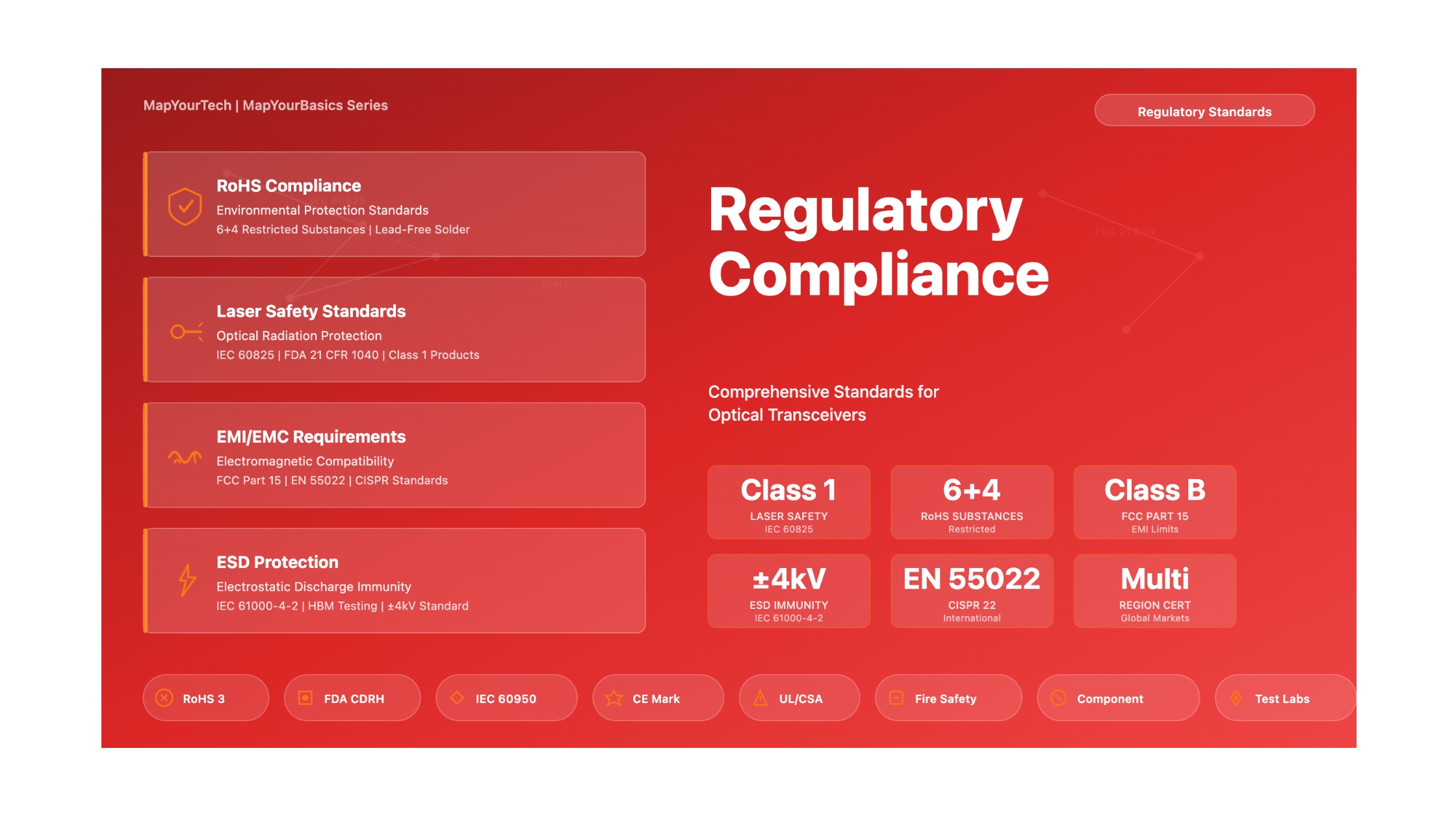
- RoHS Compliance: Restrict six hazardous substances (Pb, Hg, Cd, Cr6+, PBB, PBDE) plus four phthalates to specified maximum concentrations. Lead-free solder and halogen-free materials are industry standard. Testing via XRF screening and ICP-OES confirmation.
- Laser Safety: Class 1 or Class 1M classification typical for optical transceivers. Compliance with IEC 60825-1 (international) and FDA 21 CFR 1040 (US). Proper labeling and user documentation required. No special safety measures needed for Class 1 products.
- EMI/EMC: Class A limits standard for commercial equipment; Class B more stringent for residential use. FCC Part 15 (US) and EN 55022/CISPR 22 (international) define emission limits. ESD immunity per IEC 61000-4-2, typically Level 2 (±4 kV contact discharge) for data center equipment.
- Electrical Safety: IEC/EN 60950 or newer IEC 62368-1 standards. UL recognition for component-level safety. Fire safety through proper material selection (UL 94 V-0 rating typical).
- Documentation: Test reports from accredited laboratories, Declarations of Conformity, technical files with design documentation, material declarations from supply chain, and proper product labeling and user documentation.
The certification process typically requires 3-6 months from design finalization to market authorization, with costs ranging from $10,000 to $30,000 depending on product complexity and scope of testing. Parallel testing programs for different regulatory requirements can reduce time to market, while design-for-compliance approaches minimize the risk of failures requiring design iteration.
Successful compliance requires collaboration across multiple disciplines: electrical engineers ensuring EMC performance, optical engineers managing laser safety, materials engineers addressing RoHS requirements, quality engineers maintaining documentation and traceability, and regulatory specialists navigating the complex landscape of international requirements. The investment in comprehensive compliance programs protects manufacturers from liability, enables market access, and demonstrates commitment to safety and environmental responsibility.
Conclusion
Regulatory compliance for optical transceivers continues to evolve as technology advances and regulatory frameworks adapt to emerging challenges. The transition to higher data rates (400G, 800G, and beyond) introduces new EMC challenges from increased clock frequencies and faster signal edge rates. Environmental regulations continue to expand, with proposals for additional substance restrictions and extended producer responsibility requirements. Laser safety standards are being updated to address new wavelengths and power levels in coherent transmission systems and spatial division multiplexing.
Network engineers, system integrators, and transceiver manufacturers must remain vigilant in monitoring regulatory changes and industry trends. Participation in standards development organizations, industry associations, and technical forums provides early awareness of upcoming requirements and opportunities to influence standards development. Establishing relationships with accredited test laboratories and regulatory consultants supports efficient compliance while navigating the complex international regulatory landscape.
The fundamental goal of all these regulations—ensuring safe, reliable, environmentally responsible optical transceivers—aligns perfectly with the interests of manufacturers, network operators, and end users. By embracing compliance as an integral part of product development rather than a burdensome requirement, the optical transceiver industry continues to deliver innovative solutions that meet the world's growing need for high-speed, reliable telecommunications infrastructure while protecting human health and the environment for future generations.
References
Regulatory Standards and Directives:
- European Parliament and Council, "Directive 2011/65/EU on the restriction of the use of certain hazardous substances in electrical and electronic equipment (RoHS 2)."
- European Commission, "Directive 2015/863/EU amending Annex II to Directive 2011/65/EU (RoHS 3)."
- IEC 60825-1, "Safety of laser products - Part 1: Equipment classification and requirements."
- FDA, "21 CFR Part 1040 - Performance Standards for Light-Emitting Products."
- FCC, "47 CFR Part 15 - Radio Frequency Devices."
- IEC/EN 55022 (CISPR 22), "Information technology equipment - Radio disturbance characteristics - Limits and methods of measurement."
- IEC 61000-4-2, "Electromagnetic compatibility (EMC) - Part 4-2: Testing and measurement techniques - Electrostatic discharge immunity test."
- IEC 61000-4-3, "Electromagnetic compatibility (EMC) - Part 4-3: Testing and measurement techniques - Radiated, radio-frequency, electromagnetic field immunity test."
- IEC 60950-1, "Information technology equipment - Safety - Part 1: General requirements."
- IEC 62368-1, "Audio/video, information and communication technology equipment - Part 1: Safety requirements."
Industry Standards Organizations:
- International Electrotechnical Commission (IEC) - www.iec.ch
- Federal Communications Commission (FCC) - www.fcc.gov
- U.S. Food and Drug Administration (FDA) - www.fda.gov
- CISPR (International Special Committee on Radio Interference)
- Underwriters Laboratories (UL) - www.ul.com
Industry Reference Material:
- SFF Committee, "SFP MSA (Multi-Source Agreement)" - Defines form factor and electrical specifications.
- QSFP-DD MSA, "Quad Small Form Factor Pluggable Double Density Multi-Source Agreement."
- IEEE 802.3, "Ethernet Standards" - Defines physical layer specifications for optical transceivers.
- ITU-T G Series Recommendations - Optical transmission systems and equipment.
Recommended Reading:
Sanjay Yadav, "Optical Network Communications: An Engineer's Perspective" – Bridge the Gap Between Theory and Practice in Optical Networking.

Optical Communications & Network Automation Expert | Author of 3 Books for Optical Engineers | Founder, MapYourTech
Optical networking engineer with nearly two decades of experience across DWDM, OTN, coherent optics, submarine systems, and cloud infrastructure. Founder of MapYourTech. Read full bio →
Follow on LinkedIn