
Multi-Layer Encryption in Optical Fiber Networks
Pros, Cons, and Strategic Implementation
Introduction
Securing data as it traverses optical fiber networks has become a mission-critical requirement in an era where global communications infrastructure carries trillions of dollars in financial transactions, sensitive government intelligence, healthcare records, and the backbone traffic of the internet itself. The velocity and volume of data transmitted over modern optical networks—now routinely operating at 400 Gb/s, 800 Gb/s, and beyond—create an unprecedented concentration of valuable information within single fiber strands. This concentration makes optical infrastructure an attractive target for sophisticated adversaries ranging from nation-state actors to organized cybercriminal enterprises.
Unlike traditional copper-based networks that radiate electromagnetic signals susceptible to remote interception, optical fiber confines light signals within glass cores, creating an initial perception of inherent security. However, this assumption has been systematically dismantled by research demonstrating that fiber tapping can be executed with minimal signal loss, making detection extraordinarily difficult. The vulnerability is further compounded by the physical accessibility of fiber infrastructure—thousands of kilometers of submarine cables crossing ocean floors, metropolitan fiber rings running through publicly accessible ducts, and data center interconnects spanning multiple jurisdictions.
The industry's response to these threats has produced a sophisticated multi-layer security architecture where encryption can be implemented at different layers of the OSI model, each offering distinct advantages, limitations, and use cases. Understanding this layered approach requires examining not just the cryptographic mechanisms themselves, but the fundamental trade-offs between performance, security coverage, operational complexity, and cost. This guide provides a comprehensive analysis of encryption at Layer 1 (Physical/Optical Transport Layer), Layer 2 (Data Link Layer with MACsec), and Layer 3 (Network Layer with IPsec), enabling network architects and security professionals to make informed decisions about protecting their optical infrastructure.
Why Multi-Layer Encryption Matters
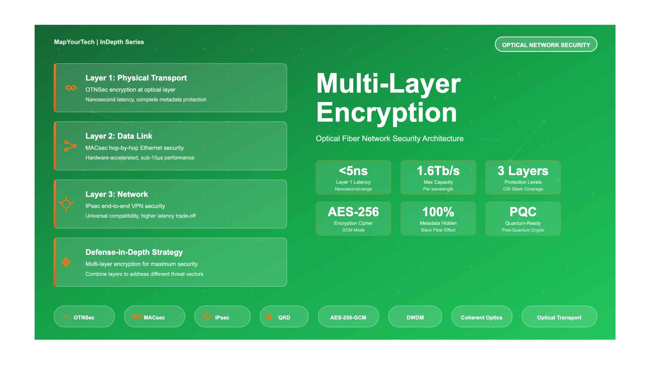
Modern optical networks require defense-in-depth strategies where different encryption layers address different threat models. Layer 1 encryption protects against physical fiber tapping and provides complete metadata obscurity. Layer 2 encryption secures hop-by-hop Ethernet connectivity with minimal performance impact. Layer 3 encryption enables end-to-end security over untrusted networks but introduces performance penalties. The optimal security architecture often combines multiple layers to address specific operational requirements and threat landscapes.
1. Overview of Encryption Layers in Optical Networks
1.1 The OSI Model and Security Placement
The Open Systems Interconnection (OSI) model provides a conceptual framework for understanding where security mechanisms can be implemented within network architectures. This seven-layer model separates network functions into distinct abstraction levels, from physical signal transmission at Layer 1 to application-specific protocols at Layer 7. For optical network encryption, the critical implementation points are Layer 1 (Physical/Transport), Layer 2 (Data Link), and Layer 3 (Network).
Each layer presents unique opportunities and constraints for encryption deployment. Lower layers offer broader protocol coverage and better performance characteristics but may require specialized hardware. Higher layers provide greater flexibility and easier integration with existing infrastructure but introduce processing overhead and latency. The strategic choice of encryption layer fundamentally shapes the security architecture, operational complexity, and performance profile of the entire network.
1.2 Why Encryption Stops at Layer 3: Understanding the Architecture
When examining the diagram showing encryption at Layers 1, 2, and 3, a natural question arises: why doesn't encryption extend to Layers 4 through 7? This is not an oversight but rather a carefully designed architectural decision based on fundamental principles of network security, operational requirements, and the distinct purposes served by different protocol layers. Understanding this design choice reveals the elegant logic underlying modern network security.
The foundational principle guiding encryption placement is simple yet powerful: encrypt data as close to the physical transmission medium as possible. This approach works because the OSI model is hierarchical—each layer builds upon and encapsulates the layers above it. When you encrypt at Layer 1, the physical transport layer, you are simultaneously protecting everything that rides on top of it: Layer 2 frames, Layer 3 packets, Layer 4 segments, and all the way up through Layer 7 application data. Think of this like Russian nesting dolls, where protecting the outermost doll automatically protects all the smaller dolls nested inside it.
To understand why this matters, imagine you are sending a confidential letter. You could seal the letter in an envelope, place that envelope in a locked box, and then transport the box in an armored truck. This is analogous to Layer 1 encryption—the armored truck (physical layer protection) secures everything inside it. Now imagine instead only sealing the letter but leaving it visible through a transparent envelope and carrying it openly in your hand. This is what happens when you encrypt only at higher layers—the content might be protected, but enormous amounts of information about the communication remains visible to anyone watching.
The Nested Protection Principle
Each layer in the OSI model wraps the layer above it with additional headers and processing. Layer 4 wraps Layer 5-7 data, Layer 3 wraps Layer 4, Layer 2 wraps Layer 3, and Layer 1 transmits the entire structure as optical signals. When encryption occurs at Layer 1, an adversary tapping the fiber sees only undecipherable light patterns. When encryption occurs at Layer 3, they can still see Layer 2 MAC addresses. When encryption occurs only at Layer 7, they can see IP addresses, port numbers, packet sizes, timing patterns, and routing information—a treasure trove of intelligence even without reading the encrypted content itself.
Layer 4: The Redundancy Problem
Layer 4, the Transport Layer, handles end-to-end connections between applications using protocols like TCP (Transmission Control Protocol) and UDP (User Datagram Protocol). At first glance, encrypting here might seem logical—after all, it provides end-to-end security between communicating applications. However, this would be redundant with Layer 3 IPsec encryption, which already provides end-to-end security for IP packets and everything they carry, including TCP and UDP segments.
More problematically, encrypting at Layer 4 as infrastructure encryption would break essential network services. Network equipment along the path needs to read TCP and UDP port numbers to perform critical functions. Routers use port numbers to make forwarding decisions and apply quality of service policies. Firewalls examine port numbers to enforce security policies. Load balancers read port numbers to distribute traffic across multiple servers. Network Address Translation devices modify port numbers to enable multiple devices to share a single public IP address. If Layer 4 headers were encrypted as part of network infrastructure protection, all of these essential services would cease to function.
Consider a practical example: when you make a Voice over IP phone call, your network needs to prioritize your voice packets over someone else's file download to ensure clear audio quality without delay or jitter. The network identifies voice traffic by examining the UDP port numbers that VoIP protocols use. If these port numbers were encrypted at Layer 4, the network would be blind to what type of traffic it was handling, treating your urgent voice packets with the same priority as bulk file transfers, resulting in choppy, unintelligible phone conversations.
Layers 5-6: The Vanishing Layers
Layers 5 and 6—the Session Layer and Presentation Layer—represent an interesting case because they have largely vanished from modern networking. When the OSI model was designed in the late 1970s and early 1980s, these layers seemed essential. Layer 5 was meant to handle session establishment, maintenance, and teardown. Layer 6 was designed to handle data format translation, character encoding, and compression.
In practice, however, modern networking protocols do not cleanly separate these functions into distinct layers. The Internet Protocol suite, which forms the foundation of today's networks, bundles session management and data presentation directly into application protocols. When you browse a website, session management happens within the HTTP protocol itself at Layer 7, not in a separate Layer 5 protocol. Data format negotiation and compression occur as features of TLS (Transport Layer Security) or within application protocols, not as standalone Layer 6 services.
Because Layers 5 and 6 do not exist as separate, distinct entities in modern networks, there is nothing to encrypt at these layers. They are conceptual divisions that made sense when the OSI model was designed but do not correspond to actual protocols or systems that could be encrypted in contemporary network architecture. It would be like trying to add a security lock to a door that was never built.
Layer 7: Application Security, Not Infrastructure Security
Layer 7, the Application Layer, does indeed use encryption extensively—but it serves a completely different purpose than the infrastructure encryption we have been discussing throughout this guide. This distinction is crucial to understand because confusion between these two types of encryption is common and leads to misunderstandings about network security architecture.
Infrastructure encryption at Layers 1 through 3 protects data as it moves through network equipment—optical transponders, switches, routers, and transmission systems owned and operated by network providers. This encryption protects against threats like fiber tapping, compromised network devices, rogue network administrators, and surveillance of telecommunications infrastructure. When data is encrypted at Layer 1, even the network operators themselves cannot see what information is being transmitted.
Application-layer encryption at Layer 7, by contrast, provides end-to-end security between applications, completely independent of the underlying network infrastructure. When you visit your bank's website using HTTPS, the TLS encryption protecting your session occurs at Layer 7. Your web browser encrypts data before sending it to the bank's server, and the server decrypts it after receiving it. This encryption protects your information from the application's perspective, ensuring that even if the data passes through dozens of networks, routers, and internet service providers, only the bank's server can decrypt and read it.
These two types of encryption complement rather than replace each other. To understand why both are necessary, imagine sending a sealed letter through the postal system. The seal on the envelope represents Layer 7 application encryption—only the intended recipient can open and read the letter. However, the envelope itself still has your return address and the recipient's address printed on the outside, along with stamps indicating when and where it was mailed. This metadata is visible to every postal worker, sorting machine, and delivery truck that handles the letter. If the government wanted to know who you communicate with, how often, and when, they could gather all of this intelligence without ever opening a single envelope.
Now imagine placing that sealed envelope inside an opaque security bag that also hides the addresses and routing information. This represents infrastructure encryption at Layers 1-3. Even though the letter inside was already sealed, the additional layer of protection prevents anyone from knowing who is communicating with whom, creating a much more robust security posture. This is why major banks, government agencies, and security-conscious organizations use both application-layer encryption for their services and infrastructure-layer encryption for their networks.
Real-World Example: Online Banking Transaction
When you log into your bank's mobile app and transfer money, multiple encryption layers protect different aspects of that transaction. At Layer 7, TLS encryption protects your username, password, account numbers, and transaction details from the moment they leave your phone until they reach the bank's application server. This ensures that even if your traffic passes through a coffee shop's WiFi, your internet service provider, and multiple backbone networks, the application data remains secure.
At Layer 3, your bank's network uses IPsec VPN tunnels to connect its data centers, branch offices, and processing systems across the internet. This protects the IP packets carrying your transaction from surveillance by internet backbone operators, foreign governments monitoring international links, or sophisticated adversaries with access to network infrastructure.
At Layer 1, within the bank's data center, optical fiber links connecting database servers, transaction processors, and security systems use hardware-based encryption operating at 400 gigabits per second. This protects against insider threats from data center technicians, physical tapping of fiber cables, or compromised network equipment within the secure facility.
Each layer addresses a different threat. Remove Layer 7 encryption, and application developers could see your passwords and account numbers. Remove Layer 3 encryption, and backbone operators could map your bank's network topology and traffic patterns. Remove Layer 1 encryption, and anyone with physical access to the data center could tap the fibers and intercept transaction data. The complete security architecture requires all three layers working together, each protecting against threats that the others do not address.
The Metadata Exposure Problem
One of the most compelling reasons why infrastructure encryption at Layers 1-3 remains essential even when application-layer encryption exists is the metadata exposure problem. Metadata—information about communication rather than the communication content itself—provides astonishingly valuable intelligence to adversaries, often more valuable than the encrypted content.
Even when your web traffic is encrypted with HTTPS, every router along the path can observe your source IP address, the destination IP address of the websites you visit, the size of data transfers, the timing and frequency of connections, and patterns in your network activity. Intelligence agencies have demonstrated repeatedly that this metadata can reveal who you communicate with, what services you use, your daily routines, your location, your associations, and your behavior patterns—all without ever breaking the encryption or reading a single byte of actual content.
For example, if an analyst sees that your IP address connects to a specific medical facility's server every Tuesday at 2 PM, they can infer you have a standing medical appointment without ever knowing what medical condition you are being treated for. If they see large file transfers between your company and a competitor's network, they can infer business negotiations are underway without knowing the terms being discussed. If they observe your connection patterns change suddenly, they can detect that something significant has occurred in your organization or personal life.
Layer 1 encryption eliminates this metadata leakage entirely by encrypting the complete payload including all IP headers, MAC addresses, port numbers, and protocol identifiers. This creates what security professionals call the "black fiber" effect—adversaries observing the physical link see nothing but undecipherable encrypted data with no information about what protocols are being used, who is communicating, or what services are being accessed. This complete metadata obscurity is impossible to achieve with application-layer encryption alone.
Performance and Scalability Considerations
Another practical reason why infrastructure encryption occurs at lower layers rather than at the application layer involves performance and scalability. When encryption happens at Layer 7 within applications, every web server, application server, and database system must perform cryptographic operations using their general-purpose CPUs. A busy website handling millions of HTTPS connections simultaneously must encrypt and decrypt each one using the server's processor, consuming significant computational resources that could otherwise be used for application logic.
Infrastructure encryption at Layer 1 or Layer 2, by contrast, uses specialized cryptographic hardware integrated directly into network equipment. Optical transponders contain dedicated Application-Specific Integrated Circuits designed specifically for high-speed encryption, operating at line rate with latency measured in nanoseconds. A single optical transponder can encrypt 800 gigabits per second of traffic while adding less than five nanoseconds of delay—performance that would be utterly impossible using software encryption on general-purpose servers.
This architectural separation allows applications to focus on application logic while network infrastructure handles transport-layer security, resulting in both better application performance and better security. Application servers are not burdened with encrypting every packet they send, and network operators can deploy cutting-edge encryption technologies without requiring any changes to the applications running on top of the infrastructure.
Why Higher-Layer Encryption Would Break the Internet
Perhaps the most practical reason why encryption does not occur at Layers 4-7 as infrastructure encryption is that doing so would fundamentally break how the internet operates. Modern networks depend on intermediate systems being able to read and act upon information in protocol headers at various layers.
Content Delivery Networks cache frequently accessed web pages and videos at servers located close to users, dramatically improving performance and reducing bandwidth costs. However, CDNs need to read HTTP headers to understand what content is being requested and whether it can be served from cache. If HTTP headers were encrypted end-to-end as infrastructure protection, CDNs could not function, and internet performance would degrade catastrophically.
Similarly, load balancers distribute incoming requests across pools of servers to prevent any single server from becoming overwhelmed. They make these distribution decisions by examining HTTP headers, session cookies, and URL paths. Proxy servers optimize bandwidth usage by compressing content and caching responses. Intrusion prevention systems examine packet contents to detect and block malicious traffic. All of these critical internet services require visibility into upper-layer protocols.
The current architecture—where infrastructure encryption protects lower layers while allowing intermediate services to operate at higher layers—represents a carefully balanced compromise. Applications that need end-to-end confidentiality use Layer 7 encryption via TLS. Networks that need to protect infrastructure and eliminate metadata leakage use Layer 1-3 encryption. Services that need to examine traffic for legitimate purposes can do so at layers where such examination is both necessary and appropriate.
Understanding the Distinction: Infrastructure vs. Application Encryption
Infrastructure Encryption (Layers 1-3): Protects data during transmission through network equipment. Performed by network devices (optical transponders, switches, routers). Protects against network-level threats like fiber tapping, compromised routers, and backbone surveillance. Operates transparently to applications. Uses hardware acceleration for maximum performance.
Application Encryption (Layer 7): Protects data end-to-end between applications. Performed by application software (web browsers, mobile apps, servers). Protects against application-level threats like compromised servers and man-in-the-middle attacks. Requires application awareness and support. Uses software libraries like OpenSSL or TLS stacks.
Both are necessary: Infrastructure encryption addresses threats that application encryption cannot, and vice versa. A complete security architecture requires both, deployed where each provides maximum benefit with minimum operational impact.
1.3 Data-in-Motion vs. Data-at-Rest
A fundamental distinction in network security architecture separates data-at-rest encryption from data-in-motion encryption. Data-at-rest encryption protects information stored on physical media such as solid-state drives, hard disk arrays, tape libraries, or database systems. These mechanisms ensure that if storage media is physically stolen or improperly decommissioned, the data remains cryptographically protected and inaccessible without proper keys.
Data-in-motion encryption, by contrast, addresses the vulnerability window when information traverses network infrastructure between secure endpoints. This is the domain where optical network encryption operates. The threat model assumes that adversaries have physical or logical access to network infrastructure and can intercept, copy, or manipulate data as it flows through fiber cables, optical amplifiers, wavelength switches, or cross-connect facilities. Multi-layer encryption in optical networks specifically targets this data-in-motion threat, creating cryptographic boundaries at different protocol layers to establish defense-in-depth.
2. Layer 1 Encryption: OTNSec (Optical Transport Network Security)
2.1 Technical Architecture
Layer 1 encryption, often implemented as OTNSec (Optical Transport Network Security), operates at the physical transport layer by encrypting the complete client payload before it is mapped into higher-layer network protocols. This approach represents the most fundamental level of network security, sitting beneath all protocol stacks and providing blanket protection regardless of the data types or applications being carried. The encryption occurs within the optical transponder or muxponder hardware itself, integrated directly into the Digital Signal Processor (DSP) or Application-Specific Integrated Circuit (ASIC) that handles optical signal modulation and demodulation.
The cryptographic foundation of modern Layer 1 encryption uses the Advanced Encryption Standard (AES) with 256-bit keys operating in Galois/Counter Mode (GCM). AES-256-GCM provides both confidentiality through encryption and integrity/authenticity through cryptographic checksums, creating authenticated encryption that detects any tampering attempts. The implementation leverages dedicated hardware encryption engines capable of processing data at line rates from 10 Gb/s to 800 Gb/s and beyond, with latency measured in nanoseconds rather than microseconds or milliseconds.
The encryption process operates on OTN frames at the ODU (Optical Data Unit) layer. The entire client payload—which may contain Ethernet, IP, Fibre Channel, SONET/SDH, or other protocols—is encrypted as an undifferentiated block of data. From the encryptor's perspective, the payload is simply a stream of bits requiring protection, making the solution inherently protocol-agnostic. Key exchange typically occurs through the OTN overhead bytes or through dedicated auxiliary channels, using mechanisms like Diffie-Hellman or Elliptic Curve Cryptography to establish shared secrets without transmitting keys in the clear.
2.2 Advantages of Layer 1 Encryption
Line-Rate Performance
Hardware-integrated encryption engines operate at full optical line rates from 10 Gb/s to 800 Gb/s and beyond, with nanosecond-range latency that is imperceptible to applications. Unlike software-based encryption that introduces measurable delays, Layer 1 encryption adds virtually no latency overhead.
Protocol Transparency
Encrypts the entire ODU payload regardless of content, simultaneously protecting Ethernet, IP, Fibre Channel, SONET, OTN, and any other protocols without requiring protocol-specific configuration or separate encryption appliances for each service type.
Complete Metadata Obscurity
Creates "black fiber" effect by encrypting all client headers and metadata including IP addresses, MAC addresses, protocol identifiers, and port numbers. This defeats traffic analysis and denies adversaries the reconnaissance intelligence needed for targeted attacks.
Zero Bandwidth Overhead
Unlike IPsec which adds additional packet headers, Layer 1 encryption consumes no additional bandwidth. The encrypted payload fits within the same OTN frame structure as unencrypted data, maximizing transport efficiency.
Operational Simplicity
Single encryption solution protects all traffic types, eliminating the complexity of managing multiple protocol-specific encryption systems. Integrated into transport equipment, reducing deployment and management overhead.
Future-Proof Scalability
Hardware encryption engines scale seamlessly with optical transmission speeds. As networks evolve from 400 Gb/s to 800 Gb/s to 1.6 Tb/s per wavelength, Layer 1 encryption maintains zero-latency performance characteristics.
2.3 Limitations and Considerations
Key Limitations to Consider
Point-to-Point Only: Layer 1 encryption is inherently a point-to-point solution between optical transponders. It cannot provide end-to-end security across multiple network domains with different operators or equipment vendors unless those domains have compatible encryption implementations and key management systems.
Equipment Dependency: Requires encryption-capable optical transport equipment at both ends of the link. Legacy or low-cost equipment without integrated encryption engines cannot participate in encrypted links, necessitating hardware upgrades or forklift replacements.
Key Management Complexity: While OTN provides auxiliary channels for key exchange, establishing and maintaining cryptographic keys across large networks with hundreds or thousands of encrypted links requires robust key management infrastructure and operational procedures.
Cost Premium: Encryption-capable transponders typically carry a 10-30% price premium over non-encrypted variants. For large-scale deployments, this incremental cost must be justified by security requirements and potential revenue from selling encrypted services.
Troubleshooting Visibility: Complete payload encryption eliminates the ability to perform in-flight packet inspection or deep packet analysis for troubleshooting purposes. This requires alternative diagnostic approaches and may complicate fault isolation.
3. Layer 2 Encryption: MACsec (IEEE 802.1AE)
3.1 Technical Architecture and Evolution
Media Access Control Security (MACsec), standardized as IEEE 802.1AE, operates at the Data Link Layer providing hop-by-hop encryption of Ethernet frames between adjacent network devices. The standard has evolved significantly since its 2006 introduction, expanding from the original GCM-AES-128 cipher to include GCM-AES-256 in the 2011 revision. The 2013 update introduced GCM-AES-XPN-128 and GCM-AES-XPN-256 variants with 64-bit packet numbers specifically designed for high-speed links above 40 Gb/s where traditional 32-bit sequence numbers would wrap too quickly.
MACsec's architectural advantage lies in its implementation at the Physical Layer (PHY) interface rather than as a centralized processing function. This per-port hardware acceleration enables line-rate encryption from 1 Gb/s to multi-hundred gigabit speeds with constant, predictable latency. Modern implementations like Cisco's ASR 9000 100GE line cards deliver 1 Tb/s of AES-256 encryption per port regardless of packet size, fully leveraging router forwarding capacity without introducing bottlenecks.
The encryption process operates on complete Ethernet frames including payload and Layer 3/4 headers, but leaves the Ethernet source and destination MAC addresses exposed to enable frame forwarding through Layer 2 infrastructure. This selective protection creates both an advantage—allowing switches to make forwarding decisions without decryption—and a limitation—exposing metadata that can reveal network topology and communication patterns to adversaries with physical access to network infrastructure.
3.2 Advantages of MACsec
Hardware-Accelerated Performance
PHY-layer implementation delivers line-rate encryption with consistent sub-10 microsecond latency across 1 Gb/s to multi-hundred gigabit speeds. Modern ASICs handle encryption without impacting forwarding capacity or introducing packet size dependencies.
Standards-Based Interoperability
IEEE 802.1AE standard ensures multi-vendor compatibility. Equipment from Cisco, Juniper, Arista, Nokia, and other vendors can establish encrypted links using standardized key exchange protocols and cipher suites.
Layer 2-7 Service Support
Hop-by-hop decryption allows intermediate switches and routers to perform QoS classification, traffic engineering, deep packet inspection, and other services on cleartext packets. This enables sophisticated network services while maintaining security between hops.
Simplified Key Management
Point-to-point nature of MACsec between adjacent devices simplifies key distribution compared to complex multi-hop scenarios. 802.1X authentication frameworks integrate naturally with enterprise identity management systems.
WAN Extension Support
WAN MACsec enhancements allow 802.1Q VLAN tags to remain visible for QoS prioritization, custom EAPoL MAC addressing for carrier Ethernet compatibility, and support for point-to-multipoint deployments over metro and wide-area networks.
Integrated Switch/Router Deployment
MACsec capabilities increasingly integrated into standard Ethernet switches and routers without requiring separate encryption appliances. This reduces capital costs and simplifies network architecture compared to overlay encryption solutions.
3.3 Limitations and Trade-offs
Key Limitations
- Protocol Specificity: MACsec only protects Ethernet frames. Networks carrying Fibre Channel storage traffic, SONET/SDH legacy circuits, or other non-Ethernet protocols require separate encryption solutions, increasing complexity and cost.
- Metadata Exposure: MAC addresses remain visible to enable Layer 2 forwarding. This leaks network topology information and communication patterns that sophisticated adversaries can exploit for reconnaissance and targeted attacks.
- Hop-by-Hop Vulnerability: Data decrypts at every intermediate switch or router, creating exposure points. A compromised device in the path can access cleartext traffic, unlike Layer 1 encryption where data remains protected throughout transit.
- Point-to-Point Scope: Encryption terminates at each network device rather than extending end-to-end. This requires trusting intermediate infrastructure and all network operators in the path.
- Key Management Complexity: Large networks with thousands of MACsec-enabled links require sophisticated key management infrastructure to handle key generation, distribution, rotation, and lifecycle management across all adjacencies.
- Limited Cross-Domain Support: MACsec typically operates within single administrative domains. Extending encryption across multiple operators or untrusted networks requires additional security layers like IPsec.
Strategic Advantages
- Campus/Metro Optimization: Ideal for securing Ethernet-based campus networks, metropolitan area networks, and data center interconnects where all traffic is Ethernet and intermediate services are required.
- Cost-Effective Deployment: Integrated into standard switching/routing hardware without requiring dedicated encryption appliances. Per-port encryption scales economically as network grows.
- Service Provider Flexibility: Enables carriers to offer encrypted Ethernet services while maintaining ability to perform traffic management, monitoring, and value-added services on customer traffic.
- Compliance Framework: Meets regulatory requirements for protecting data-in-motion in many industries including healthcare (HIPAA), finance (PCI-DSS), and government (FIPS 140-2 certified implementations).
- Incremental Deployment: Can be enabled selectively on specific links or network segments without requiring wholesale infrastructure changes. Supports phased migration to encrypted operations.
- Operations Integration: Fits naturally into existing network management workflows. Standard SNMP, NETCONF, and vendor management platforms provide visibility and control over MACsec links.
4. Layer 3 Encryption: IPsec (Internet Protocol Security)
4.1 Technical Architecture and Mode Operations
Internet Protocol Security (IPsec) operates at the Network Layer providing end-to-end encryption of IP packets across untrusted networks. Unlike Layer 1 and Layer 2 encryption which protect physical links or Layer 2 adjacencies, IPsec creates secure tunnels between endpoints that can traverse multiple network domains, operators, and technologies without requiring any cooperation or awareness from intermediate infrastructure. This end-to-end model makes IPsec the foundation of Virtual Private Networks (VPNs) used by remote workers, branch offices, and inter-organization communications over the public internet.
IPsec implements two primary modes of operation that serve different use cases. Transport Mode encrypts only the IP packet payload, leaving the original IP header intact to enable native routing. This mode is typically used for host-to-host communications where both endpoints support IPsec. Tunnel Mode, by contrast, encrypts the entire original IP packet including headers, then encapsulates the encrypted payload in a new IP packet with new source and destination addresses. This creates a secure tunnel between security gateways and is the standard approach for site-to-site VPNs connecting corporate networks across the internet.
The cryptographic foundation of IPsec uses a suite of protocols including Authentication Header (AH) for integrity and authentication, Encapsulating Security Payload (ESP) for confidentiality and optional authentication, and Internet Key Exchange (IKE) for automated key negotiation and security association establishment. Modern deployments predominantly use ESP with AES-256 encryption in either CBC or GCM modes, coupled with IKEv2 for streamlined connection establishment and rekeying operations.
4.2 Advantages of IPsec
End-to-End Security
Provides encryption between endpoints regardless of intermediate network infrastructure. Data remains protected across multiple operators, public internet segments, and untrusted networks without requiring any security awareness from intermediate devices.
Universal Compatibility
Works over any IP-capable network including internet, private MPLS networks, wireless links, and satellite connections. No special hardware or operator support required in the transport path.
Mature Ecosystem
Decades of deployment experience have produced robust implementations, extensive vendor support, proven security architectures, and comprehensive management tools. Nearly every firewall, router, and security appliance supports IPsec.
Remote Access Enablement
Native support for mobile and remote users accessing corporate resources from any location. VPN clients available for all operating systems and mobile devices enable secure workforce mobility.
Multi-Protocol Support
Protects any protocol carried over IP including TCP, UDP, ICMP, and application-specific protocols. Single IPsec tunnel can secure diverse traffic types without protocol-specific configuration.
Flexible Deployment Models
Supports host-to-host, host-to-network, and network-to-network architectures. Can be deployed on endpoints, security gateways, or as overlay on existing infrastructure without requiring changes to core network.
4.3 Performance Challenges and Limitations
IPsec Performance Considerations
IPsec typically runs as CPU-intensive single-threaded process on x86 machines rather than hardware-accelerated PHY-layer encryption. This architectural approach results in significantly higher latency (100-500+ microseconds) compared to MACsec (sub-10 microseconds) and Layer 1 encryption (nanosecond range). The performance impact becomes more pronounced as link speeds increase and with smaller packet sizes that characterize VoIP and IoT traffic.
Most commercial firewalls and routers implementing IPsec cap out at throughput levels well below 100 Gb/s even with hardware acceleration, making IPsec unsuitable for high-capacity optical backbone encryption. A 10 Gb/s IPsec gateway might handle only 3-5 Gb/s of actual encrypted throughput depending on packet size and cipher suite complexity. This performance ceiling creates a fundamental mismatch with modern optical networks operating at 400 Gb/s, 800 Gb/s, and beyond.
Critical IPsec Limitations
Metadata Exposure: In tunnel mode, IPsec encrypts the original IP packet but adds a new unencrypted IP header containing tunnel endpoint addresses. This outer header exposes source and destination information that adversaries can use for traffic analysis, network mapping, and targeted attacks even without breaking encryption.
Complex Key Management: Large-scale IPsec deployments with thousands of tunnels require sophisticated PKI infrastructure, certificate management, IKE policy coordination, and security association lifecycle management. Operational complexity increases dramatically with network size.
Bandwidth Overhead: IPsec adds 50-70 bytes of overhead per packet including new IP header, ESP header, padding, and authentication trailer. For small packets, this overhead can consume 10-15% of available bandwidth, reducing effective throughput.
Fragmentation Issues: IPsec tunnel mode increases packet size, potentially causing IP fragmentation if MTU is not properly configured. Fragmented IPsec packets can cause performance degradation and compatibility problems with network devices that don't handle fragments efficiently.
NAT Traversal Complexity: Network Address Translation breaks standard IPsec operation by modifying IP headers that are protected by IPsec authentication. NAT-T (NAT Traversal) provides workarounds but adds complexity and may not work in all network scenarios.
5. Comprehensive Layer Comparison and Decision Framework
5.1 Technical Specifications Comparison
| Characteristic | Layer 1 (OTNSec) | Layer 2 (MACsec) | Layer 3 (IPsec) |
|---|---|---|---|
| OSI Layer | Physical/Transport Layer | Data Link Layer | Network Layer |
| Encrypted Unit | Entire ODU payload (all protocols) | Ethernet frame payload | IP packet payload or entire packet |
| Protocol Support | Protocol agnostic: Ethernet, Fibre Channel, SONET, IP, OTN | Ethernet only | Any protocol over IP |
| Typical Latency | Nanosecond range (<5 ns) | Microseconds (<10 μs) | 100-500+ microseconds |
| Bandwidth Overhead | Zero (no additional headers) | Minimal (adds SecTAG + ICV) | Significant (adds ESP header + new IP header in tunnel mode) |
| Metadata Protection | Complete: All headers encrypted including IP, MAC, protocols | Partial: MAC addresses exposed, IP/upper layers encrypted | Partial: Outer IP header exposed in tunnel mode |
| Implementation | Integrated in optical transponder hardware (ASIC/DSP) | PHY-layer hardware in switches/routers | Software or dedicated crypto processor |
| Security Scope | Point-to-point between optical transponders | Hop-by-hop between adjacent devices | End-to-end across multiple networks |
| Maximum Practical Speed | 800 Gb/s to 1.6 Tb/s (proven) | Multi-hundred Gb/s per port | Typically <100 Gb/s (appliance-dependent) |
| Standards | ITU-T G.709 (OTN), proprietary vendor extensions | IEEE 802.1AE, 802.1X for authentication | IETF RFC 4301 (IPsec), RFC 7296 (IKEv2) |
| Key Cipher | AES-256-GCM | AES-128-GCM or AES-256-GCM | AES-256-CBC/GCM, 3DES (legacy) |
| Typical Deployment | High-speed DCI, financial networks, government/defense | Campus/metro networks, carrier Ethernet, data center | VPN over internet, remote access, site-to-site |
| Cost Model | 10-30% premium on optical transponders | Often integrated in modern switches at minimal cost | Separate VPN appliances or firewall features |
| Intermediate Device Visibility | Zero (complete black fiber) | MAC addresses visible; decrypts at each hop for services | Outer IP visible; payload encrypted end-to-end |
| Traffic Analysis Resistance | Excellent (no metadata leakage) | Moderate (MAC patterns visible) | Moderate (tunnel endpoints visible) |
5.2 Use Case Decision Matrix
Selecting the appropriate encryption layer requires careful analysis of network architecture, performance requirements, threat model, operational constraints, and budget. The following decision framework helps network architects and security professionals determine which encryption layer—or combination of layers—best addresses their specific requirements.
| Scenario | Recommended Layer | Rationale |
|---|---|---|
| High-frequency trading network requiring sub-microsecond latency | Layer 1 (OTNSec) | Nanosecond-range latency is critical; even MACsec's microsecond delays are unacceptable. Protocol agnosticism protects all proprietary trading protocols. |
| Campus network securing Ethernet-based communications | Layer 2 (MACsec) | All traffic is Ethernet; low latency with hardware acceleration; integrated into existing switches; enables QoS and traffic management. |
| Remote worker VPN access over internet | Layer 3 (IPsec) | Must traverse untrusted public internet; end-to-end security required; no control over intermediate infrastructure; acceptable latency for typical applications. |
| Data center interconnect carrying multi-protocol storage and IP traffic | Layer 1 (OTNSec) | Protocol agnosticism protects both Fibre Channel and Ethernet; terabit-scale capacity; zero latency critical for synchronous replication. |
| Metropolitan area network connecting branch offices | Layer 2 (MACsec) | Controlled infrastructure with trusted operator; all Ethernet traffic; benefits from carrier QoS and traffic engineering capabilities. |
| Government backbone requiring maximum security classification | Layer 1 (OTNSec) | Complete metadata obscurity defeats traffic analysis; NATO/EU approved solutions available; no exposure at intermediate points. |
| Multi-site enterprise network across different countries | Layer 3 (IPsec) | Multiple operators and jurisdictions; no ability to deploy Layer 1/2; end-to-end encryption over untrusted paths essential. |
| Healthcare provider connecting hospitals with patient data | Layer 1 or Layer 2 | HIPAA compliance requires encryption; if dedicated fiber infrastructure exists use Layer 1; if carrier Ethernet service use MACsec. |
| Financial institution interconnecting global trading centers | Layer 1 (OTNSec) | Ultra-low latency for competitive advantage; complete security for high-value transactions; dedicated optical infrastructure justifies investment. |
| Service provider offering encrypted WAN services to customers | Layer 2 (MACsec) | Standards-based solution with multi-vendor support; enables value-added services; hop-by-hop model allows provider network management. |
| Defense network carrying classified information | Layer 1 + Layer 2 or 3 | Defense-in-depth: Layer 1 for transport-level protection; additional layer for segmentation and end-to-end security across domains. |
| Cloud provider building regional data center network | Layer 1 (OTNSec) | Terabit-scale capacity required; controls entire infrastructure; protocol agnosticism supports diverse customer services; maximum performance. |
6. Strategic Advantages and Limitations Summary
6.1 Layer 1 (OTNSec): The Performance Champion
Strategic Advantages
- Ultimate performance: Line-rate encryption at 10G to 1.6T+ with nanosecond latency
- Protocol agnosticism: Simultaneously protects Ethernet, Fibre Channel, SONET, IP, OTN without configuration
- Complete metadata obscurity: "Black fiber" effect provides total traffic analysis resistance
- Zero bandwidth overhead: No additional headers or encapsulation required
- Future-proof scalability: Hardware encryption scales seamlessly with optical transmission speeds
- Operational simplicity: Single solution protects all traffic types
- Counter-intelligence capability: Denies adversaries reconnaissance information
- Compliance advantage: Meets highest security classifications (NATO/EU approved)
Key Limitations
- Point-to-point only: Cannot provide end-to-end security across multiple domains
- Equipment dependency: Requires encryption-capable optical transponders at both ends
- Capital cost: 10-30% premium on optical transport equipment
- Key management: Complex in large networks with thousands of encrypted wavelengths
- Vendor lock-in risk: Proprietary extensions may limit multi-vendor interoperability
- Troubleshooting challenges: Complete encryption eliminates in-flight packet inspection
- Geographic scope: Typically limited to single administrative domain or trusted partners
6.2 Layer 2 (MACsec): The Balanced Solution
Strategic Advantages
- Low latency: Hardware PHY-layer acceleration delivers sub-10 microsecond performance
- Standards-based: IEEE 802.1AE ensures multi-vendor interoperability
- Integrated deployment: Built into modern switches and routers at minimal incremental cost
- Service enablement: Hop-by-hop decryption allows QoS, traffic engineering, DPI
- WAN extension: Supports carrier Ethernet and metro network deployments
- Simplified key management: Point-to-point between adjacent devices reduces complexity
- Line-rate performance: Hardware acceleration up to multi-hundred Gbps per port
- Incremental deployment: Can be enabled selectively without infrastructure changes
Key Limitations
- Ethernet-only: Cannot protect Fibre Channel, SONET, or other non-Ethernet protocols
- Metadata exposure: MAC addresses remain visible, revealing network topology
- Hop-by-hop vulnerability: Data decrypts at each device, creating exposure points
- Limited scope: Point-to-point security between adjacent devices, not end-to-end
- Trust requirement: Must trust all intermediate network devices in the path
- Key management at scale: Thousands of MACsec links require sophisticated management
- Cross-domain challenges: Difficult to extend encryption across multiple operators
6.3 Layer 3 (IPsec): The Universal Option
Strategic Advantages
- End-to-end security: Protects data across multiple networks and operators
- Universal compatibility: Works over any IP network including internet
- Mature ecosystem: Decades of deployment with extensive vendor support
- Remote access: Native support for mobile workers and distributed workforce
- No infrastructure requirements: Operates as overlay without network changes
- Multi-protocol support: Protects any protocol running over IP
- Flexible deployment: Host-to-host, host-to-network, network-to-network models
- Cross-domain capability: Easily extends security across organizational boundaries
Key Limitations
- High latency: CPU-intensive processing adds 100-500+ microseconds
- Performance ceiling: Typically caps below 100 Gbps even with hardware acceleration
- Metadata exposure: Tunnel mode exposes outer IP headers for traffic analysis
- Bandwidth overhead: Adds 50-70 bytes per packet, reducing effective throughput
- Complex key management: PKI infrastructure required for large deployments
- Fragmentation issues: Increased packet size can cause MTU problems
- NAT traversal: Requires special handling when Network Address Translation present
- Operational complexity: Configuration and troubleshooting can be challenging
7. Defense-in-Depth: Combining Multiple Encryption Layers
7.1 Why Multi-Layer Encryption Makes Sense
The most robust optical network security architectures do not rely on a single encryption layer but instead implement defense-in-depth strategies that combine multiple layers to address different threat vectors and operational requirements. This approach recognizes that each encryption layer has specific strengths and limitations, and that layering them strategically creates resilience against a broader spectrum of attacks while maintaining operational flexibility.
A defense-in-depth encryption strategy might implement Layer 1 OTNSec to protect the optical transport infrastructure against physical fiber tapping and to ensure protocol-agnostic blanket security. On top of this foundation, Layer 2 MACsec could be deployed selectively at metro aggregation points to enable traffic engineering and QoS while maintaining hop-by-hop security. Finally, Layer 3 IPsec would provide end-to-end application security for specific high-value traffic flows that traverse multiple administrative domains or untrusted network segments.
Real-World Defense-in-Depth Example: Global Financial Institution
Layer 1 (OTNSec): Deployed on all inter-data-center links carrying trading systems, transaction processing, and storage replication. Provides maximum performance (sub-5 nanosecond latency) with complete metadata obscurity. Protects both Ethernet and Fibre Channel traffic with single solution.
Layer 2 (MACsec): Implemented on campus networks connecting trading floors, back-office systems, and branch offices. Hardware-accelerated with low latency, enables network monitoring and QoS for different traffic classes. Standards-based interoperability with multi-vendor infrastructure.
Layer 3 (IPsec): Used for remote worker access, third-party connectivity, and connections to cloud services over internet. Provides end-to-end encryption across untrusted networks where organization has no infrastructure control. Integrates with existing VPN infrastructure.
Result: Comprehensive security coverage addressing physical tapping threats, insider threats at network layer, and external threats from internet-based attacks. Each layer optimized for its specific role without compromising overall performance or operational flexibility.
7.2 Common Multi-Layer Architectures
Layer 1 + Layer 3 Combination
Architecture: OTNSec protects optical transport infrastructure while IPsec provides end-to-end security for specific applications traversing multiple domains.
Use Case: Government networks where Layer 1 protects classified backbone transport and IPsec enables secure connectivity to coalition partners or cloud services.
Benefit: Maximum transport security combined with flexible end-to-end protection across untrusted boundaries.
Layer 2 + Layer 3 Combination
Architecture: MACsec secures campus/metro Ethernet infrastructure while IPsec protects remote access and inter-site connectivity over internet.
Use Case: Enterprise networks with headquarters campus, branch offices connected via internet, and remote workforce requiring VPN access.
Benefit: Hardware-accelerated LAN security combined with universal remote access capability without requiring optical infrastructure investment.
All Three Layers Combined
Architecture: Layer 1 for optical backbone, Layer 2 for metro aggregation, Layer 3 for end-to-end application security and remote access.
Use Case: Critical infrastructure operators (power grid, telecommunications, financial systems) requiring maximum security depth.
Benefit: Defense-in-depth with each layer addressing specific threat vectors; redundancy ensures security even if one layer is compromised.
Layer 1 + Application-Layer Encryption
Architecture: OTNSec protects transport while applications implement TLS/SSL for end-to-end security independent of network infrastructure.
Use Case: Cloud service providers protecting both infrastructure (Layer 1) and customer data (application layer) with zero-trust architecture.
Benefit: Transport-level blanket security combined with fine-grained application control; customers maintain encryption keys independent of provider.
8. Future Directions: Post-Quantum Cryptography and Emerging Threats
8.1 The Quantum Computing Threat
The impending arrival of fault-tolerant quantum computers capable of running Shor's algorithm threatens to break the public-key cryptographic foundations that underpin current key exchange mechanisms in all three encryption layers. While symmetric encryption algorithms like AES-256 remain quantum-resistant (requiring only modest key length increases), the RSA and Elliptic Curve Cryptography used for key establishment and authentication in Layer 1, Layer 2, and Layer 3 encryption systems face existential threats from quantum computing advances expected within the next decade.
This quantum threat is not theoretical speculation but an active area of concern acknowledged by government agencies, standards bodies, and industry leaders. The U.S. National Institute of Standards and Technology (NIST) released the first three finalized Post-Quantum Cryptography (PQC) standards in August 2024, marking a critical milestone in the transition to quantum-safe cryptography. These standards—FIPS 203 (ML-KEM), FIPS 204 (ML-DSA), and FIPS 205 (SLH-DSA)—provide quantum-resistant alternatives for key encapsulation and digital signatures that will form the foundation of next-generation secure communications.
Industry Response to Quantum Threat
Ribbon Communications Apollo Platform (2020-Present): Field-proven quantum-safe optical networking deployed in production carrier and enterprise networks worldwide. The Apollo platform provides AES-256-GCM Layer 1 optical encryption supporting speeds from 100 Gb/s to 1.2 Tb/s with zero latency overhead and virtually no performance penalty. Apollo supports both Post-Quantum Cryptography (PQC) key exchange algorithms including KEM (Key Encapsulation Mechanism) for encryption and SIG (Digital Signature) for authentication, running in parallel with or as replacement for conventional Diffie-Hellman algorithms. The platform also supports Quantum Key Distribution (QKD) integration for maximum security assurance. External Key Management (EKM) capability enables enterprises leasing encrypted optical connections from service providers to manage all aspects of key administration themselves via secure web-based applications. Real-world validation came in September 2024 when Sparkle and Telsy successfully demonstrated QKD integration over Apollo's 400 Gbps links between data centers in Athens, Greece. In January 2025, Ribbon deployed Apollo's quantum-safe optical network for EENet, Estonia's Education and Research Network, enabling secure collaboration within the pan-European research community. At OFC 2025, Ribbon showcased the Apollo 9408 and 9458 Compact Modular Transport platforms achieving industry-highest 25.6 Tb/s line capacity in 2RU form factor with ultra-low power consumption for webscale operators.
Nokia Quantum-Safe Networks (2018-Present): Comprehensive defense-in-depth quantum-safe solution built around the 1830 Photonic Service Switch (PSS) family and 1830 Security Management Server (SMS) providing centralized symmetric key generation and distribution. In November 2024, Nokia achieved industry-first NIST FIPS 140-3 Security Level 2 Validation certification for Layer 1 optical transport covering 1830 PSS, PSI-M, and PSS-24x platforms including software, equipment controllers, management interfaces and encryptors. This two-year certification effort demonstrates Nokia's commitment to advancing security standards for mission-critical optical networks ready for the quantum age. The 1830 SMS generates high-quality quantum-safe keys from physical spawned entropy using powerful processors and security-enhanced operating systems. Production deployments span critical infrastructure globally. In January 2025, SK Broadband deployed Nokia's quantum-safe network protecting Korea Hydro and Nuclear Power (KHNP) IT infrastructure using advanced MACsec cryptographic technology. Portuguese operator IP Telecom deployed Nokia's encrypted 100 Gbps and 200 Gbps optical DCI solution in 2022 connecting Lisbon, Porto, and Viseu with quantum-safe key management. SK Telecom's 2020 Seoul deployment demonstrated QKD-integrated optical encryption on commercial production network. November 2025 trials with Proximus demonstrated hybrid quantum encryption keys in live Belgian optical networks. Nokia Bell Labs collaborates with Honeywell and Colt Technology Services on satellite-based QKD with 2026 testing and 2027 commercial launch targeted. The solution provides crypto-resilient multi-layered security across optical (OTNsec), Ethernet (MACsec), MPLS and IP (IPsec) layers with AES-256 encryption, complemented by optical intrusion detection using wavelength tracking and OTDR capabilities.
ADVA Network Security (2021): First vendor to implement post-quantum cryptography in Layer 1 optical encryption, demonstrating proactive approach to quantum threats before NIST standardization was complete.
Ciena WaveLogic 6 Extreme (2024-2025): Late 2024 availability with mass adoption surge throughout 2025. Shipping with industry-leading 1.6 Tb/s per wavelength encrypted capacity using advanced 3nm coherent DSP technology operating at 200 GBaud. By end of fiscal year 2025, 72 customers worldwide deployed WL6e achieving unprecedented performance records. Arelion achieved world's first live 1.6 Tb/s wave data transmission in 2025. Telstra set world-first speed and distance records. euNetworks became first European operator deploying 1.6 Tb/s wavelength. Colt Technology Services completed world's first terabit wavelength transmission across the Atlantic. December 2025 saw Constl achieve breakthrough 1 Tbps transmission over 1,450 km Mumbai-Chennai route. In 2025, Ciena confirmed the industry's only 1.6 Tb/s encryption offering supporting both Quantum Key Distribution (QKD) and Post-Quantum Cryptography (PQC) integration. Platform designed with upgrade path for quantum-safe key exchange mechanisms as standards continue to mature.
Chinese Research (2025): Demonstrated 1 Tbps secure optical transmission over 1,200 km using Integrated Encryption and Communication framework combining quantum noise stream cipher with deep learning. Achieves one-time-pad level security at terabit speeds with firmware-upgrade deployment path in existing coherent transponders.
Standards Evolution: ETSI released GS QKD 016 in April 2023 as world's first Protection Profile for Quantum Key Distribution. ITU-T and ISO/IEC established dedicated quantum technology committees accelerating international standardization of quantum-safe communications. NIST finalized first three PQC standards (FIPS 203, 204, 205) in August 2024, providing foundation for industry-wide quantum-safe transition with widespread implementation throughout 2025-2026.
8.2 Quantum Key Distribution (QKD): The Ultimate Secure Key Exchange
Quantum Key Distribution represents a fundamentally different approach to secure key establishment, leveraging the laws of quantum mechanics rather than mathematical complexity to guarantee security. Unlike classical cryptography where security depends on computational hardness assumptions that quantum computers can break, QKD's security derives from the Heisenberg Uncertainty Principle and the quantum no-cloning theorem—physical laws that cannot be circumvented by any amount of computational power.
QKD systems transmit cryptographic keys encoded in quantum states of single photons over optical fiber. Any attempt by an eavesdropper to intercept and measure these quantum states inevitably disturbs them, introducing detectable errors that alert the legitimate parties to the presence of the attacker. This intrinsic eavesdropping detection makes QKD information-theoretically secure, providing security guarantees that no classical cryptographic system can match.
8.3 Post-Quantum Migration Roadmap
The transition to quantum-safe optical network encryption will occur gradually over the next 5-10 years as standards mature, implementations are validated, and equipment upgrade cycles enable deployment. Network operators should begin planning now for this migration to ensure continued security in the post-quantum era. The following roadmap outlines recommended steps for organizations protecting optical infrastructure.
Phase 1: Assessment (2025-2026)
Inventory cryptographic assets: Document all encryption systems across Layer 1, 2, and 3 including algorithms, key lengths, and key exchange mechanisms currently deployed.
Identify quantum-vulnerable systems: Prioritize systems using RSA or ECC for key exchange that will require PQC upgrades.
Establish threat timeline: Determine organizational risk tolerance and acceptable migration timeline based on data sensitivity and threat model.
Phase 2: Hybrid Deployment (2026-2028)
Implement hybrid cryptography: Deploy systems supporting both classical (RSA/ECC) and post-quantum algorithms simultaneously to ensure backward compatibility while establishing quantum resistance.
Pilot PQC implementations: Test NIST-approved algorithms (ML-KEM, ML-DSA, SLH-DSA) in non-production environments to validate performance and interoperability.
Begin equipment refresh: Replace encryption equipment reaching end-of-life with PQC-capable alternatives where available.
Phase 3: QKD for Critical Links (2027-2030)
Deploy QKD on highest-value links: Install quantum key distribution systems on most critical connections including financial trading networks, government backbones, and primary data center interconnects.
Integrate QKD with Layer 1 encryption: Use quantum-generated keys to enhance OTNSec implementations providing information-theoretic security for transport encryption.
Establish quantum key management infrastructure: Build centralized or federated systems for managing, distributing, and rotating quantum-derived cryptographic keys across network.
Phase 4: Full PQC Migration (2029-2032)
Complete transition to PQC: Replace all remaining classical key exchange mechanisms with post-quantum alternatives as standards solidify and equipment becomes widely available.
Disable classical-only modes: Remove support for non-quantum-safe algorithms once all endpoints have been upgraded to prevent downgrade attacks.
Continuous monitoring and updates: Maintain vigilance as quantum computing capabilities evolve and cryptographic standards are refined based on real-world deployment experience.
9. Conclusion and Strategic Recommendations
The security of data traversing optical fiber networks has evolved from an afterthought to a mission-critical requirement driving infrastructure investment decisions and shaping network architectures. This comprehensive analysis of multi-layer encryption demonstrates that there is no single universal solution—rather, each encryption layer addresses specific requirements, threat models, and operational constraints. Layer 1 OTNSec provides unparalleled performance and complete metadata obscurity but requires specialized optical transport equipment. Layer 2 MACsec offers an excellent balance of low latency and standards-based interoperability for Ethernet networks but exposes MAC addresses and operates hop-by-hop. Layer 3 IPsec enables end-to-end security across untrusted networks but introduces significant latency and performance limitations unsuitable for high-speed optical backbones.
The strategic imperative for network architects is to understand these trade-offs deeply and implement appropriate encryption layers—or combinations of layers—aligned with specific use cases. High-frequency trading networks and government defense systems will gravitate toward Layer 1 for its nanosecond latency and complete traffic analysis resistance. Enterprise campus networks and metro Ethernet services find Layer 2 MACsec optimal for balancing security with network services enablement. Remote access and multi-domain connectivity rely on Layer 3 IPsec despite its performance penalties because it works universally over any IP network.
Looking forward, the quantum computing threat looms as a transformative challenge requiring proactive migration planning. The deployment of Post-Quantum Cryptography algorithms standardized by NIST in 2024, combined with strategic implementation of Quantum Key Distribution for the most sensitive links, will define the next generation of optical network security. Organizations must begin inventory and assessment now, implement hybrid classical/quantum cryptography during the 2026-2028 transition period, and complete full migration to quantum-safe systems by the early 2030s before fault-tolerant quantum computers become operational realities.
Key Strategic Recommendations
For High-Performance Networks: Prioritize Layer 1 (OTNSec) encryption on all high-capacity links (400G+) where sub-microsecond latency is critical. The 10-30% equipment premium is justified by complete security coverage and future-proof scalability to terabit speeds.
For Campus/Metro Networks: Deploy Layer 2 (MACsec) widely leveraging hardware acceleration integrated in modern switches and routers. The minimal incremental cost and standards-based interoperability make this the default choice for Ethernet-based infrastructure.
For Cross-Domain Connectivity: Use Layer 3 (IPsec) when connecting across untrusted networks, multiple operators, or where end-to-end application security is required independent of transport infrastructure.
For Defense-in-Depth: Combine multiple layers where security requirements justify the investment. Layer 1 for transport protection plus Layer 3 for application security provides redundant safeguards against different attack vectors.
For Quantum Readiness: Begin assessment phase immediately, implement hybrid PQC systems during equipment refresh cycles, and plan strategic QKD deployment on most critical links by 2028-2030 timeframe.
The convergence of increasing bandwidth demands, sophisticated threat actors, and the quantum computing timeline creates an unprecedented imperative for robust optical network encryption. Organizations that strategically implement appropriate multi-layer security architectures today—while planning proactively for the post-quantum transition tomorrow—will maintain secure, high-performance networks capable of protecting critical information assets throughout the coming decades of technological evolution.
References and Further Reading
Standards Bodies and Technical Organizations:
- ITU-T Recommendation G.709 – Interfaces for the optical transport network (OTN)
- IEEE 802.1AE-2018 – Media Access Control (MAC) Security
- IETF RFC 4301 – Security Architecture for the Internet Protocol (IPsec)
- IETF RFC 7296 – Internet Key Exchange Protocol Version 2 (IKEv2)
- NIST FIPS 203, 204, 205 – Post-Quantum Cryptography Standards
- ETSI GS QKD 002, 004, 005, 008, 011, 014, 016 – Quantum Key Distribution standards series
Vendor Technical Documentation:
- Ciena Corporation – WaveLogic Encryption technical specifications and deployment guides
- ADVA Network Security – ConnectGuard Layer 1 encryption solutions and post-quantum implementations
- Ribbon Communications – Optical networking security solutions and encryption implementations
- PacketLight Networks – Layer 1 Encryption over DWDM white papers
- Cisco Systems – MACsec deployment guides for ASR 9000 and Catalyst platforms
- Juniper Networks – WAN MACsec implementation and best practices
Essential Reading:
Sanjay Yadav, "Optical Network Communications: An Engineer's Perspective" – Bridge the Gap Between Theory and Practice in Optical Networking.
Book Link: Available on Amazon
Developed by MapYourTech Team
For educational purposes in Optical Networking Communications Technologies
Note: This guide is based on industry standards, best practices, and real-world implementation experiences. Specific implementations may vary based on equipment vendors, network topology, and regulatory requirements. Always consult with qualified network engineers and follow vendor documentation for actual deployments.
Feedback Welcome: If you have any suggestions, corrections, or improvements to propose, please feel free to write to us at:
[email protected]

Optical Communications & Network Automation Expert | Author of 3 Books for Optical Engineers | Founder, MapYourTech
Optical networking engineer with nearly two decades of experience across DWDM, OTN, coherent optics, submarine systems, and cloud infrastructure. Founder of MapYourTech. Read full bio →
Follow on LinkedIn