28 min read

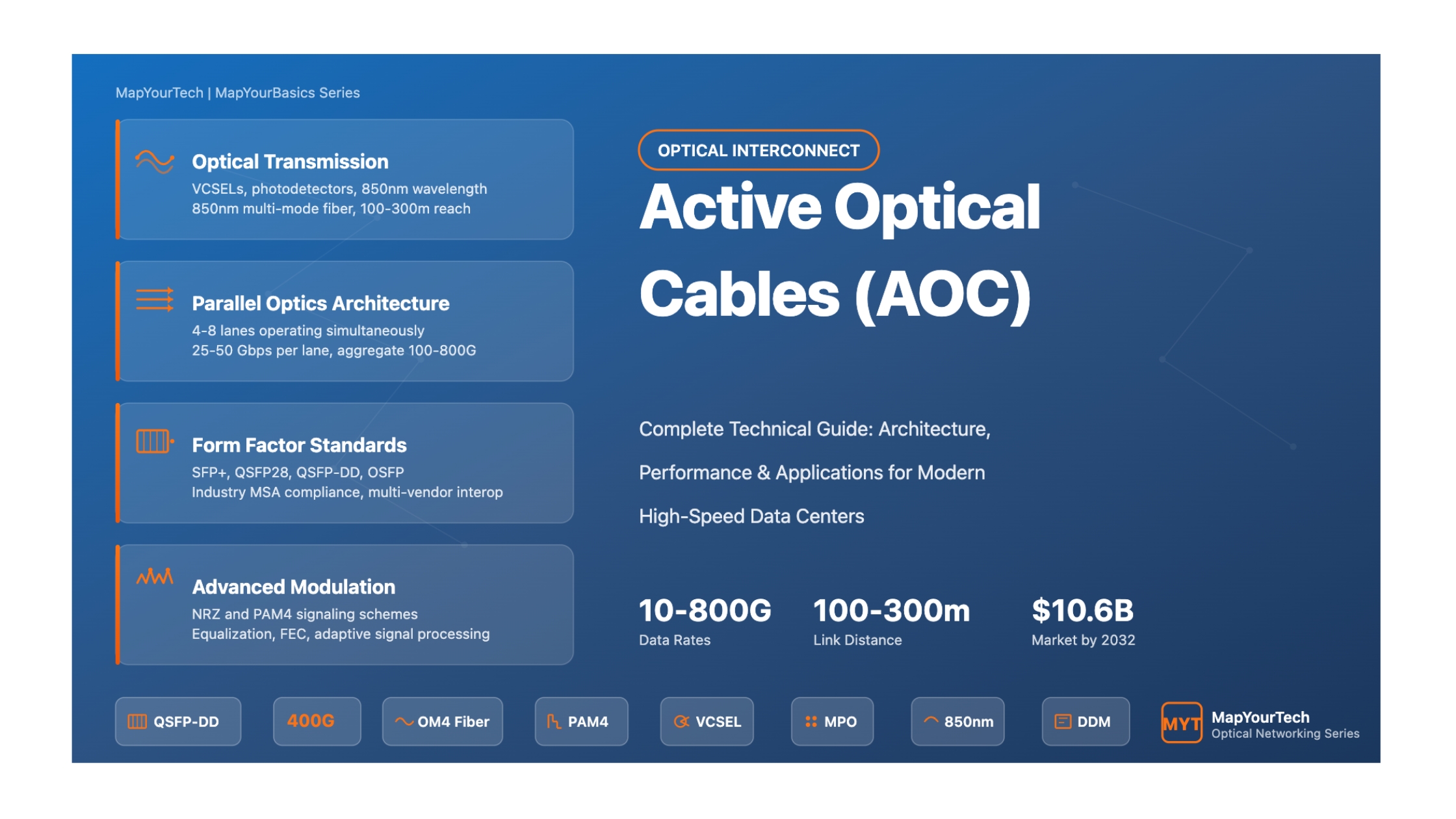
Active Optical Cables (AOC): Complete Educational Guide
Master the fundamentals, architecture, and applications of high-speed Active Optical Cable technology for modern data centers and telecommunications
Introduction to Active Optical Cables
In the rapidly evolving landscape of data communications and high-performance computing, Active Optical Cables (AOCs) have emerged as a transformative technology that bridges the gap between traditional copper cabling and standalone optical transceivers. As organizations worldwide grapple with exponentially growing bandwidth demands, limited data center space, and the need for longer interconnect distances, AOCs present an elegant solution that combines the best attributes of both copper and fiber optic technologies.
Active Optical Cables represent a paradigm shift in how we approach short to medium-range data transmission. Unlike traditional passive copper cables that transmit electrical signals directly through metal conductors, AOCs employ optical fiber technology with integrated electrical-to-optical (E-O) and optical-to-electrical (O-E) converters embedded within the cable connectors. This innovative design allows AOCs to accept standard electrical interfaces while leveraging the superior performance characteristics of optical fiber for data transmission, creating a plug-and-play solution that requires no additional transceivers or patch panels.
An Active Optical Cable is an advanced cabling assembly that integrates fiber optic technology with active electronic components to enable high-speed data transmission over distances that would be impractical or impossible with traditional copper cables. At its core, an AOC consists of optical transceivers permanently attached to both ends of a fiber optic cable, sealed within ruggedized connectors that match industry-standard form factors such as SFP+, QSFP+, QSFP28, QSFP-DD, and OSFP.
The fundamental architecture of an AOC includes several key components working in concert. At the transmit end, the electrical signals from the host device are converted into optical signals using laser diodes or VCSELs (Vertical-Cavity Surface-Emitting Lasers). These optical signals travel through the fiber optic cable—typically multi-mode fiber for data center applications—with minimal attenuation and zero electromagnetic interference. At the receive end, photodiodes detect the optical signals and convert them back into electrical signals that the receiving device can process.
AOCs support data rates from 10 Gbps to 800 Gbps and beyond, with newer generations reaching multi-terabit speeds. The optical fiber core provides virtually unlimited bandwidth compared to copper alternatives.
While copper cables are typically limited to 5-7 meters for high-speed applications, AOCs can reliably transmit data over distances of 100 meters or more, with some configurations reaching 300 meters.
Optical transmission is completely immune to electromagnetic interference (EMI) and radio frequency interference (RFI), ensuring signal integrity even in electrically noisy environments.
Optical signals cannot be tapped or intercepted without physically breaking the fiber, providing inherent security advantages over copper cables that can be susceptible to signal interception.
The importance of Active Optical Cables in contemporary data infrastructure cannot be overstated. As we witness the proliferation of bandwidth-intensive applications—from artificial intelligence and machine learning workloads to 8K video streaming and real-time big data analytics—the limitations of traditional copper interconnects become increasingly apparent. AOCs address these challenges while offering several compelling advantages that make them indispensable in modern network architectures.
First and foremost, AOCs enable data centers to achieve higher port densities and more efficient use of limited rack space. The lightweight, flexible nature of AOC cables—typically weighing only 25% of equivalent copper cables—facilitates easier cable management and improved airflow within equipment racks. This translates directly into better cooling efficiency and reduced power consumption for environmental control systems.
The cost-effectiveness of AOCs becomes particularly evident when considering total cost of ownership. While the initial per-unit cost of an AOC may exceed that of a short copper cable, the elimination of separate transceivers, reduced power consumption (AOCs typically use 30-40% less power than comparable copper solutions at high data rates), and simplified installation significantly lower the overall deployment and operational costs. Furthermore, the sealed design of AOCs eliminates the risk of fiber end-face contamination, a leading cause of optical network failures that can result in costly troubleshooting and downtime.
The versatility of Active Optical Cables has led to their adoption across a diverse range of applications and industries. In hyperscale data centers operated by cloud service providers, AOCs form the backbone of server-to-switch and switch-to-switch interconnects, handling massive volumes of east-west traffic between compute nodes. These environments demand the highest levels of reliability, performance, and scalability—requirements that AOCs fulfill admirably.
High-performance computing (HPC) clusters, which power scientific research, weather forecasting, and computational fluid dynamics simulations, rely heavily on AOC technology to achieve the ultra-low latency and high bandwidth necessary for parallel processing architectures. The ability to deploy AOCs in lengths up to 100 meters allows HPC facilities to design more flexible and scalable cluster topologies without being constrained by the distance limitations of copper cabling.
In the telecommunications sector, AOCs play a crucial role in 5G network infrastructure, connecting radio units to baseband processing equipment and enabling the massive MIMO (Multiple-Input Multiple-Output) antenna arrays that deliver enhanced capacity and coverage. The immunity to electromagnetic interference makes AOCs particularly valuable in cell site deployments where numerous radio frequency sources coexist in close proximity.
Consumer electronics have also embraced AOC technology, particularly in professional audio-visual applications. High-definition video production environments use AOCs to transmit uncompressed 4K and 8K video signals between cameras, switchers, and displays over distances that would be impossible with traditional HDMI or DisplayPort copper cables. The thin, flexible form factor of AOCs simplifies cable routing in complex studio setups and live event productions.
According to recent market analysis, the global Active Optical Cable market was valued at approximately $3.8-4.0 billion in 2024 and is projected to reach $8.8-10.6 billion by 2032, growing at a compound annual growth rate (CAGR) of 12-14%. This remarkable growth is driven by increasing data center investments, 5G network deployments, AI/ML workload demands, and the transition to 400G/800G network infrastructures. North America currently leads the market with over 37-40% share, followed by Asia-Pacific which represents the fastest-growing region due to massive infrastructure development in China, India, and Japan.
As we progress through this guide, several fundamental concepts will appear repeatedly, forming the foundation for more advanced topics. Understanding these key principles from the outset will enhance your ability to grasp complex technical details in later sections:
Optical-to-Electrical Conversion: The process by which AOCs transform electrical signals into photons for transmission through fiber, then reconvert them to electrical signals at the destination. This bidirectional conversion happens at nanosecond speeds with minimal latency penalty.
Multi-Mode vs. Single-Mode Fiber: Most data center AOCs utilize multi-mode fiber (MMF) with core diameters of 50 or 62.5 microns, optimized for 850nm wavelength transmission over distances up to 300 meters. Single-mode fiber (SMF), with its 9-micron core, is reserved for longer-reach applications exceeding 500 meters.
Parallel Optics Architecture: Modern high-speed AOCs employ multiple fiber pairs operating in parallel to achieve aggregate data rates. For example, a 100G QSFP28 AOC uses 4 lanes of 25 Gbps each, while 400G QSFP-DD AOCs utilize 8 lanes of 50 Gbps.
Form Factor Standards: Industry consortia including the SFF Committee, QSFP-DD MSA, and OSFP MSA have established standardized mechanical and electrical specifications that ensure interoperability between AOCs from different manufacturers and host equipment from various vendors.
Power Budget Analysis: The calculation of optical power from transmitter to receiver, accounting for fiber attenuation, connector losses, and required receiver sensitivity. Adequate power budget ensures reliable operation across the entire cable length with sufficient margin for aging and environmental variations.
With these foundational concepts established, you're now prepared to embark on a comprehensive exploration of Active Optical Cable technology. The journey ahead will equip you with the knowledge and practical skills needed to confidently specify, deploy, and troubleshoot AOC solutions in any environment. Let's begin our deep dive into the fascinating world of high-speed optical interconnects.
Historical Context & Evolution of AOC Technology
The development of Active Optical Cables represents a fascinating convergence of fiber optic technology, semiconductor innovation, and the relentless drive for higher bandwidth in computing and telecommunications. Understanding the historical trajectory of AOC technology provides valuable context for appreciating current capabilities and anticipating future developments. This evolution spans more than two decades, marked by critical breakthroughs in optoelectronics, manufacturing processes, and industry standardization efforts.
The genesis of Active Optical Cable technology can be traced to the early 2000s when the High-Performance Computing (HPC) community confronted a fundamental challenge: as InfiniBand data rates climbed toward 20 Gigabits per second (DDR InfiniBand), traditional copper interconnects became increasingly impractical. Copper cables operating at these speeds experienced severe signal degradation beyond 8-10 meters, limiting the physical layout options for large compute clusters and constraining system scalability.
In response to this limitation, pioneering companies Intel and Luxtera independently developed the first-generation AOC solutions in 2006-2007. Intel's design employed Vertical-Cavity Surface-Emitting Lasers (VCSELs) operating at 850nm wavelength, paired with discrete photodetectors and driver electronics. Luxtera took a revolutionary approach by leveraging CMOS photonics technology, integrating most transceiver functionality onto a silicon chip with only the lasers and photodetectors remaining as discrete components. This integration breakthrough, branded as the "Blazar" AOC product line, demonstrated that optical transceivers could be manufactured using modified semiconductor fabrication processes, pointing toward future cost reductions through economies of scale.
These early AOCs targeted the 10 Gigabit Ethernet and 10G InfiniBand markets, offering cable lengths up to 100 meters while maintaining compatibility with existing SFP+ electrical interfaces. The value proposition was immediately apparent: data center operators could extend interconnect distances fourfold compared to copper while simultaneously reducing cable weight and improving cable management. However, initial adoption was constrained by relatively high costs (2-3 times that of copper alternatives) and limited manufacturing volumes.
The period from 2009 to 2014 witnessed critical standardization efforts that accelerated AOC adoption across multiple market segments. The SFF (Small Form Factor) Committee published specifications for QSFP+ (Quad Small Form-Factor Pluggable) connectors in 2009, enabling the first 40 Gigabit Ethernet AOCs. This four-channel architecture, utilizing four parallel 10 Gbps lanes, became the foundation for subsequent multi-lane high-speed interconnects.
Simultaneously, the IEEE 802.3ba standard for 40G and 100G Ethernet, ratified in 2010, explicitly recognized AOC as a valid media type for data center interconnects. This formal recognition by the premier networking standards body provided the industry validation needed to justify large-scale deployments. Major equipment vendors began qualifying AOC products from multiple suppliers, breaking the market away from single-source dependencies and fostering healthy competition that drove down prices.
Manufacturing innovations during this era significantly improved AOC economics. The transition from discrete component assembly to integrated photonic circuits reduced per-unit costs by approximately 40%, making AOCs competitive with high-performance copper cables for distances beyond 5 meters. Major manufacturers established automated production lines capable of producing thousands of AOCs daily, ensuring supply could meet the exponentially growing demand from cloud service providers building massive data center campuses.
The introduction of breakout AOC configurations in 2012 represented another significant milestone. These cables feature a high-density connector on one end (e.g., QSFP+) that fans out to multiple lower-speed connectors on the other end (e.g., four SFP+ modules). Breakout AOCs enabled more flexible network topologies, allowing 40G switch ports to connect directly to four 10G servers without requiring external breakout modules or cassettes. This capability proved particularly valuable for enterprise data centers transitioning from 10G to 40G network infrastructure.
The escalation to 100 Gigabit Ethernet marked a pivotal moment in AOC evolution. The QSFP28 form factor, standardized in 2014 and deployed at scale from 2015 onward, utilized four lanes of 25 Gbps signaling—a significant jump from the 10 Gbps lanes of QSFP+. This transition necessitated advancements in both optical and electrical components to maintain signal integrity at these higher speeds.
VCSEL technology underwent substantial improvements during this period. Fourth-generation VCSELs achieved modulation bandwidths exceeding 25 GHz, enabling reliable 25 Gbps transmission with adequate power budget for 100-meter OM4 multi-mode fiber links. Photodetector responsivity and bandwidth also improved, while transimpedance amplifier (TIA) designs became more sophisticated to handle the challenging electrical characteristics of 25 Gbps signaling.
The market also witnessed the emergence of specialized AOC variants tailored for specific applications. Bidirectional AOCs, which transmit in both directions over a single fiber pair using different wavelengths, reduced fiber count and cable bulk. Temperature-hardened AOCs with extended operating ranges (-40°C to +85°C) addressed industrial and outdoor deployment requirements. Low-latency AOCs with optimized signal paths found favor in financial trading environments where every nanosecond matters.
Cloud service providers became the dominant force driving AOC innovation during this period. Companies building hyperscale data centers demanded AOCs that could operate reliably for 10+ years in challenging thermal environments, maintain bit error rates below 10^-15, and support remote management through digital diagnostic monitoring (DDM) interfaces. These stringent requirements pushed manufacturers to implement more rigorous testing protocols and quality control measures.
The current phase of AOC evolution is characterized by the rapid deployment of 400 Gigabit and 800 Gigabit Ethernet technologies, driven primarily by artificial intelligence, machine learning, and cloud computing workloads that demand unprecedented bandwidth. The QSFP-DD (Quad Small Form-Factor Pluggable Double Density) and OSFP (Octal Small Form-Factor Pluggable) form factors have emerged as the dominant standards for these ultra-high-speed applications.
QSFP-DD AOCs achieve 400G throughput using eight lanes of 50 Gbps PAM4 (Pulse Amplitude Modulation 4-level) signaling. This advanced modulation technique encodes two bits per symbol, effectively doubling the data rate without requiring proportional increases in bandwidth. PAM4 does introduce additional complexity in signal processing and requires more sophisticated equalization techniques, but the density and power efficiency benefits justify the engineering investment.
The progression to 800G has spawned innovative AOC architectures. Some implementations utilize the OSFP form factor with eight lanes of 100 Gbps PAM4, while others employ dual 400G configurations within a single QSFP-DD or OSFP footprint. These 800G AOCs represent the cutting edge of commercially available technology, supporting the voracious bandwidth appetite of AI training clusters and high-frequency trading systems.
Recent innovations have also addressed the challenge of breakout configurations at these extreme data rates. 400G-to-4x100G AOCs employ sophisticated gearbox ASICs within the high-speed connector to convert eight 50 Gbps PAM4 lanes into four 100 Gbps PAM4 lanes, enabling connections between 400G switch ports and 100G network interface cards. Similarly, 400G-to-2x200G breakout AOCs provide flexibility for networks transitioning between speed grades.
Power consumption has become a critical design consideration as data rates have increased. Modern 400G AOCs typically consume 5-7 watts per end, compared to 12-15 watts for copper alternatives at the same data rate and distance. This 50% power reduction translates directly into lower cooling requirements and reduced operational costs, a crucial advantage given the massive scale of contemporary data centers.
Several significant developments in 2023-2024 have shaped the current AOC landscape. In March 2023, major industry players demonstrated 800G AOC technology at the Optical Fiber Communication (OFC) Conference, showcasing integrated solutions that combine low latency, reduced power consumption, and enhanced bandwidth specifically optimized for AI and machine learning workloads. These demonstrations validated the technical feasibility of 800G AOCs and accelerated standardization efforts.
The launch of enhanced thermal management features in 2024 addressed one of the longstanding challenges in high-power AOC deployments. New designs incorporate improved heat dissipation through optimized connector housing materials and thermal interface materials, enabling reliable operation in dense switch environments where ambient temperatures can exceed 40°C.
Industry collaborations have also intensified, with partnerships between optical component manufacturers, semiconductor companies, and system integrators accelerating time-to-market for next-generation products. In February 2024, several major technology companies announced joint development initiatives focusing on 1.6 Terabit AOC technology using 16 lanes of 100 Gbps, targeting deployment in 2025-2026 timeframes.
The integration of artificial intelligence into AOC design and manufacturing processes represents an emerging trend. Machine learning algorithms now optimize VCSEL driving parameters for maximum output power and modulation efficiency, while AI-powered quality control systems inspect every manufactured cable for potential defects invisible to human inspectors. These technologies are improving yield rates and reducing defect densities to levels previously thought unattainable.
Looking ahead to 2025-2030, several technological trajectories appear likely to shape AOC evolution. The progression toward 1.6 Terabit and 3.2 Terabit data rates seems inevitable given current trends in data center bandwidth requirements. These ultra-high speeds will necessitate fundamental innovations in laser technology, potentially including the adoption of coherent optical transmission techniques traditionally reserved for long-haul telecommunications.
Silicon photonics integration is expected to advance significantly, with complete transceivers implemented on a single chip alongside electronic functions. This level of integration will dramatically reduce component counts, improve reliability, and enable cost reductions that make optical interconnects economically viable for even shorter distances currently served by copper.
The convergence of electrical and optical domains through co-packaged optics (CPO) represents a paradigm-shifting approach where optical transceivers are integrated directly onto switch ASICs rather than residing in edge-mounted modules. While this technology challenges the traditional AOC model, it's likely that hybrid architectures will emerge, combining CPO for the shortest connections with advanced AOCs for rack-to-rack and row-to-row interconnects.
Sustainability considerations are driving research into more environmentally friendly AOC designs. Efforts focus on reducing material usage, implementing recyclable components, and developing manufacturing processes with lower carbon footprints. The industry is also exploring biodegradable optical fiber jackets and connector housings made from recycled plastics, aligning with corporate sustainability initiatives.
The market outlook remains exceptionally strong, with multiple research firms projecting compound annual growth rates of 12-14% through 2032. This growth is fueled by data center expansion, 5G infrastructure buildout, AI/ML workload proliferation, and the ongoing digital transformation across all industry sectors. As bandwidth demands continue their exponential climb, Active Optical Cables will remain at the forefront of high-performance interconnect solutions, evolving to meet ever-more-demanding requirements while delivering increasing value to users worldwide.
Core Concepts & Fundamentals
Understanding Active Optical Cables at a fundamental level requires grasping several interconnected concepts that span optics, electronics, and telecommunications. This section provides a comprehensive foundation in the principles that govern AOC operation, explaining not just what AOCs do, but why and how they achieve their remarkable performance characteristics.
At the heart of every Active Optical Cable lies the phenomenon of total internal reflection, which enables light to propagate through optical fiber with minimal loss. When light traveling through a dense medium (the fiber core) encounters the boundary with a less dense medium (the fiber cladding) at an angle greater than the critical angle, it reflects back into the core rather than refracting through the boundary. This principle, governed by Snell's Law, allows optical signals to travel hundreds of meters with attenuation measured in tenths of decibels.
The fiber core in multi-mode AOCs typically measures 50 microns in diameter—roughly half the thickness of a human hair—surrounded by 125-micron diameter cladding. This relatively large core allows hundreds of optical modes (distinct propagation paths) to coexist, each reflecting at slightly different angles. While modal dispersion limits the bandwidth-distance product of multi-mode fiber compared to single-mode fiber, the 100-300 meter distances typical of AOC applications fall well within the capability envelope of modern laser-optimized multi-mode fiber (OM3 and OM4 grades).
The transmitter section of an AOC performs one of the most critical functions in the entire system: converting high-speed electrical data streams into optical signals suitable for fiber transmission. This process begins with the laser driver circuit, which receives differential electrical signals (typically LVDS or CML logic levels) from the host device and amplifies them to the current levels needed to modulate the laser source.
Modern AOCs predominantly employ Vertical-Cavity Surface-Emitting Lasers (VCSELs) as their optical sources. Unlike edge-emitting lasers that emit from the cleaved end of the semiconductor chip, VCSELs emit perpendicular to the chip surface through a circular aperture. This geometry offers several advantages: excellent coupling efficiency to multi-mode fiber (typically >50%), low threshold current (reducing power consumption), and compatibility with wafer-scale testing and high-volume manufacturing. VCSELs operate at 850nm wavelength, chosen for its optimal balance of low attenuation in multi-mode fiber, mature semiconductor technology, and availability of high-efficiency photodetectors.
The laser driver must precisely control the VCSEL's operating point to maintain optimal performance across varying environmental conditions. Most drivers implement both DC bias current (to maintain the laser above threshold) and AC modulation current (to encode the data). Advanced designs incorporate automatic power control (APC) loops that continuously monitor optical output power and adjust drive current to compensate for temperature drift and aging effects.
At the receiving end of an AOC, the photode tector converts incoming optical signals back into electrical form. PIN (Positive-Intrinsic-Negative) photodiodes are the dominant detector technology, offering excellent responsivity at 850nm wavelength, high bandwidth (typically >20 GHz), and reliability over billions of operating hours. When photons strike the photodiode's active region, they generate electron-hole pairs that contribute to the photocurrent proportional to the optical power incident on the detector.
The weak photocurrent (typically tens to hundreds of microamperes) must be amplified and converted to voltage signals compatible with digital logic. This function is performed by the transimpedance amplifier (TIA), a specialized analog circuit that combines high gain, wide bandwidth, and low noise. The TIA output feeds into a limiting amplifier that regenerates clean digital signals with standard LVDS or CML logic levels, removing amplitude variations and jitter accumulated during transmission.
Receiver sensitivity—the minimum optical power required to achieve a specified bit error rate (typically 10^-12 or better)—represents a critical performance parameter. Modern 25 Gbps receivers achieve sensitivities around -10 dBm, providing substantial margin over the -2 to -4 dBm transmitter output power. This 6-8 dB link budget accommodates fiber attenuation (typically 2-2.5 dB/km at 850nm), connector losses (0.5 dB per connection), and aging effects over the product lifetime.
High-speed AOCs employ parallel optics architecture to achieve aggregate data rates that would be impractical or impossible with single-channel transmission. This approach distributes the data across multiple independent optical channels, each operating at a moderate speed that mature transceiver technology can reliably handle. For example, a 100G QSFP28 AOC utilizes four optical lanes, each transmitting 25 Gbps, rather than attempting to transmit 100 Gbps on a single lane.
The parallel architecture offers several compelling advantages beyond technological feasibility. Power consumption scales favorably because four 25 Gbps lanes typically consume less total power than a single 100 Gbps lane would require (if such technology existed). Manufacturing yields improve because the relaxed per-lane speed requirements reduce the statistical probability of defects. System reliability increases through redundancy—if one lane develops issues, the link can potentially continue operating at reduced capacity rather than failing completely.
Inside the AOC connector, a sophisticated interposer or flex circuit fans out the high-density electrical interface to individual laser and photodetector sites. This routing must maintain controlled impedance (typically 100 ohms differential) and minimize crosstalk between adjacent lanes. At the fiber interface, a precision-molded MPO (Multi-fiber Push-On) connector simultaneously aligns all fiber cores to their respective transceivers with submicron accuracy.
Maintaining signal integrity across the entire transmission path—from host device through electrical interface through optical transmission through electrical interface to receiving device—requires careful attention to numerous factors that can degrade signal quality. On the electrical side, impedance matching, via inductance, trace inductance, and return path discontinuities all contribute to intersymbol interference (ISI) that smears signal edges and reduces timing margin.
The optical transmission path introduces its own impairments. Modal dispersion occurs because different optical modes travel at slightly different velocities through the fiber, causing pulse spreading that limits bandwidth. Chromatic dispersion, arising from the wavelength-dependent refractive index of the fiber material, further contributes to pulse spreading though it's less significant at 850nm than at longer wavelengths used in long-haul transmission. Polarization mode dispersion (PMD), caused by birefringence in the fiber, becomes relevant only at very high speeds or long distances, remaining negligible in typical AOC applications.
To combat these impairments, modern AOCs incorporate sophisticated equalization techniques. Feed-forward equalizers (FFE) apply pre-emphasis to the transmit signal, boosting high-frequency content to compensate for predictable bandwidth limitations. Decision feedback equalizers (DFE) at the receiver use feedback from previous bit decisions to remove postcursor ISI. For the most demanding applications operating at 50+ Gbps per lane, continuous-time linear equalizers (CTLE) provide adaptive frequency-domain compensation that tracks slowly varying channel characteristics.
As data rates have climbed beyond 25 Gbps per lane, the industry has adopted PAM4 (4-level Pulse Amplitude Modulation) signaling to overcome bandwidth limitations in both electrical and optical domains. Unlike traditional NRZ (Non-Return to Zero) signaling which encodes one bit per symbol using two amplitude levels, PAM4 encodes two bits per symbol using four distinct amplitude levels. This effectively doubles the data rate for a given baud rate, or equivalently, halves the required bandwidth for a given data rate.
For example, a 50 Gbps PAM4 signal operates at 25 Gbaud—the same symbol rate as a 25 Gbps NRZ signal—but conveys twice as much information. This allows existing 25 GHz laser and photodetector technology to support 50 Gbps data rates, enabling 400G AOCs with eight 50 Gbps PAM4 lanes to be manufactured using proven components.
The trade-off for this efficiency comes in the form of reduced signal-to-noise ratio (SNR). Because PAM4 must distinguish between four amplitude levels rather than two, it requires approximately 9.5 dB better SNR than NRZ to achieve the same bit error rate. This necessitates more powerful transmitters, more sensitive receivers, better equalization, and often forward error correction (FEC) to maintain acceptable link margins. The standard IEEE 802.3 KP4 FEC commonly employed in 400G AOCs adds approximately 7% overhead but provides substantial coding gain that makes PAM4 transmission practical over multi-mode fiber.
While most AOCs utilize separate fibers for transmit and receive directions, some specialized configurations employ wavelength division multiplexing (WDM) to transmit bidirectionally over a single fiber pair. Bidirectional AOCs typically use 850nm for one direction and 900nm or 950nm for the opposite direction, with WDM filters in each transceiver separating the incoming and outgoing signals.
The primary advantage of bidirectional AOCs is the 50% reduction in fiber count, which translates to smaller cable diameter, improved flexibility, and simplified cable management. This becomes particularly valuable in space-constrained installations or when retrofitting AOCs into conduits with limited capacity. The trade-off includes slightly higher component cost (due to the WDM filters), marginally increased insertion loss (typically 0.5-1 dB for the filters), and the need for careful inventory management to ensure transmit and receive wavelengths are properly paired.
Several standardized metrics quantify AOC performance and enable meaningful comparisons between products from different manufacturers. Understanding these metrics is essential for proper system design and specification:
The ratio of incorrectly received bits to total transmitted bits. Modern AOCs typically guarantee BER better than 10^-12 (one error per trillion bits) without FEC, or 10^-15 with FEC. Lower BER indicates higher reliability and is critical for error-sensitive applications.
The time delay between signal input and output. AOC latency typically ranges from 100-300 nanoseconds depending on cable length and internal processing. Fiber propagation contributes approximately 5 nanoseconds per meter, while transceiver electronics add 50-150 nanoseconds per end.
Total electrical power drawn by the AOC transceivers. Ranges from 1.5W per end (10G SFP+) to 7W per end (400G QSFP-DD). Lower power reduces cooling requirements and operational costs, particularly important in large-scale deployments with thousands of ports.
The difference between transmitter output power and receiver sensitivity, representing available margin to overcome losses. A 6-8 dB link budget typically accommodates 100-meter OM4 fiber (2.5 dB loss), connectors (1-1.5 dB), and aging/thermal effects (2-3 dB), with 1-2 dB remaining margin.
These fundamental concepts provide the foundation for understanding more advanced topics in subsequent sections. The interplay between optical physics, semiconductor technology, and system-level design creates the remarkable capabilities of modern Active Optical Cables. As we progress through this guide, we'll build upon these principles to explore detailed architecture, practical applications, and deployment strategies that leverage AOC technology to solve real-world interconnect challenges.
Technical Architecture & Components
The architecture of an Active Optical Cable represents a sophisticated integration of optical, electrical, and mechanical engineering disciplines. Understanding the detailed construction and interoperation of AOC components provides essential insight into how these devices achieve their impressive performance characteristics while maintaining reliability across demanding operating conditions.
An AOC consists of five primary functional blocks: the host-side electrical interface, the transmit-side electrical-to-optical converter, the fiber optic cable assembly, the receive-side optical-to-electrical converter, and the remote-side electrical interface. Each block must meet strict specifications for signal integrity, power consumption, and environmental robustness.
The host-side electrical interface presents industry-standard contacts matching the form factor specification—SFP+, QSFP28, QSFP-DD, OSFP, etc. These contacts carry high-speed differential pairs (TX and RX data lanes), low-speed control signals (I2C management, ModSelL, ResetL), and power supply pins (VCC and Ground). The physical connector design must withstand hundreds of insertion-extraction cycles while maintaining electrical performance specifications across the full frequency spectrum from DC to 30+ GHz.
Inside the connector housing, a precision-engineered interposer or flexible printed circuit board (flex PCB) routes signals from the edge contacts to the transceiver components. This routing demands extraordin ary attention to transmission line theory—every trace must maintain controlled impedance (typically 100 ohms differential), minimize discontinuities at vias and layer transitions, and provide adequate spacing to prevent crosstalk between adjacent lanes. Advanced designs employ back-drilling of vias to eliminate stubs that would otherwise reflect high-frequency signal energy.
The transmitter section contains the most complex active circuitry within an AOC. At its input, the design must interface with host-side electrical signals that may range from <1 Vpp to >2 Vpp differential, accommodate significant common-mode noise, and tolerate wide timing variations due to spread-spectrum clocking in the host device. The first stage typically incorporates a high-bandwidth differential receiver with adaptive equalization to compensate for channel losses in the host PCB and connector.
Following the input receiver, a phase-locked loop (PLL) circuit performs clock recovery, extracting a clean clock signal from the incoming data stream and generating the precise timing required for VCSEL modulation. Modern PLLs employ fractional-N architectures that support wide frequency ranges (10G to 56G PAM4) with low jitter (<500 femtoseconds RMS) critical for maintaining timing budget.
The laser driver represents the critical link between electronics and photonics. This circuit must deliver precisely controlled current to the VCSEL with rise and fall times matching the bit period (25-40 picoseconds for 25G NRZ). The driver typically implements separate bias and modulation current paths—bias current maintains the VCSEL above threshold continuously, while modulation current switches rapidly to encode the data. For PAM4 signals, the driver must generate four distinct current levels with tight spacing (typically 15-25% of peak current) and excellent amplitude accuracy to maintain symbol error budget.
The VCSEL itself, while seemingly simple as a semiconductor laser, incorporates sophisticated physics. The vertical-cavity structure provides optical feedback through distributed Bragg reflector (DBR) mirrors—multilayer stacks of alternating refractive index that create interference patterns concentrating optical energy in the active region. The active region contains multiple quantum wells where electron-hole recombination produces coherent 850nm photons. Careful thermal design ensures junction temperature remains below 85°C under worst-case drive conditions to maintain output power and wavelength stability.
The optical fiber forms the transmission highway at the heart of every AOC. Most data center AOCs utilize graded-index multi-mode fiber with laser-optimized bandwidth characteristics. The graded index—a radial variation in core refractive index—partially compensates for modal dispersion by causing rays propagating at different angles to travel at different velocities, arriving simultaneously at the fiber end.
OM3 fiber provides effective modal bandwidth of 2000 MHz·km at 850nm, sufficient for 25 Gbps transmission over 100 meters with adequate margin. OM4 fiber increases this to 4700 MHz·km, extending reach to 150 meters at 25 Gbps or enabling 100 meters at 50 Gbps. The newest OM5 fiber, optimized for short-wavelength division multiplexing (SWDM), maintains OM4 performance at 850nm while adding specified performance at 880, 910, and 940nm wavelengths.
The fiber cable assembly includes protective buffering and jacketing layers. Primary buffer coating (typically acr ylate polymer) provides mechanical protection directly on the 125-micron cladding. Secondary buffering (often tight-buffered with PVC or LSZH materials) brings diameter to 900 microns, providing crush resistance and bend radius control. The outer jacket, constructed from flame-retardant thermoplastic materials, protects the internal fibers from abrasion, chemical exposure, and environmental stress. For maximum flexibility and small bend radius, modern AOCs often employ "bend-insensitive" or "bend-optimized" fibers with specialized trench-assisted designs that maintain low loss even when bent to 7.5mm radius—critical for dense cable routing.
The receiving end of an AOC must detect weak optical signals (as low as -14 dBm in some specifications) and convert them to clean electrical signals suitable for host device consumption. The photodetector, typically a PIN structure optimized for 850nm response, generates photocurrent proportional to incident optical power. Responsivity (the ratio of photocurrent to optical power) typically reaches 0.5-0.6 A/W at 850nm for optimized designs.
The transimpedance amplifier (TIA) performs current-to-voltage conversion with extraordinarily high gain (1-10 kΩ transimpedance) while maintaining bandwidth exceeding 20 GHz. This combination of high gain and wide bandwidth represents a significant technical challenge—standard amplifier theory predicts gain-bandwidth tradeoff that would seem to preclude this performance. The solution involves careful feedback network design, often using inductive peaking or active feedback compensation to extend bandwidth while maintaining stability.
Following the TIA, a limiting amplifier (LA) provides additional voltage gain and converts the analog signal to full-swing logic levels. The LA incorporates high-pass filtering to remove low-frequency baseline wander while preserving data transitions. Modern designs achieve >40 dB gain with >30 GHz bandwidth and precisely controlled output swing (800-1200 mV differential) to match host device receiver specifications. The LA often includes offset compensation circuitry that automatically corrects for DC imbalances arising from component mismatch.
For PAM4 reception, the architecture becomes more sophisticated, requiring multi-level slicing and sophisticated equalization. Three comparators establish four decision regions, with decision thresholds dynamically adjusted based on measured signal statistics. Continuous-time linear equalization (CTLE) applies frequency-domain compensation before the comparators, while decision feedback equalization (DFE) removes postcursor intersymbol interference using digital feedback from previous symbol decisions.
Power distribution within an AOC must meet multiple conflicting requirements: high efficiency to minimize heat generation, low noise to prevent interference with sensitive analog circuitry, and fast transient response to support low-power modes. The design typically incorporates multiple voltage domains: 3.3V supply from the host (occasionally 12V for high-power modules), internal buck converters generating 1.8V or 1.2V supplies for digital logic, separate low-noise linear regulators powering PLL and analog circuits, and dedicated laser driver supplies providing precise current control.
Heat removal poses particular challenges given the sealed connector design. Modern high-power AOCs (400G QSFP-DD, 800G OSFP) may dissipate 12-14 watts total. The mechanical design incorporates thermal interface materials (TIMs) that conduct heat from critical components to the connector shell, which serves as a heat sink when plugged into a cooled cage assembly. Internal thermal sensors monitor junction temperatures, triggering alarms if thermal runaway threatens. Some advanced designs implement dynamic thermal management, reducing transmitter output power slightly when temperatures exceed safe thresholds—trading modest performance degradation for continued operation.
Modern AOCs incorporate comprehensive diagnostic capabilities accessible through the I2C management interface. Per the SFF-8436 and CMIS specifications, the AOC presents memory-mapped registers containing real-time operating parameters: temperature at multiple sensor locations, supply voltage levels, transmit bias current for each channel, transmit optical power, receive optical power, and pre-forward error correction bit error rate.
These diagnostics enable proactive maintenance strategies. By trending temperature data over time, network operators can identify cooling system degradation before failures occur. Monitoring transmit optical power helps detect VCSEL aging, while receive power measurements identify fiber damage or contamination. The BER monitor provides early warning of marginal links that may soon cross error thresholds. CMIS extends these capabilities with sophisticated threshold management, allowing user-defined alarm levels for all monitored parameters.
Vertical-cavity surface-emitting lasers operating at 850nm with modulation bandwidth >25 GHz. Typical output power: -2 to +4 dBm per channel. Threshold current: 0.5-2 mA. Temperature coefficient: ~0.06 nm/°C wavelength shift.
PIN photodiodes with 850nm responsivity of 0.5-0.6 A/W. Bandwidth >25 GHz. Typical capacitance: 0.1-0.3 pF. Dark current: <1 nA. Active area: 30-80 microns diameter for optimal coupling to 50-micron fiber core.
OM3/OM4 grade 50-micron core fiber. OM3: 2000 MHz·km @ 850nm. OM4: 4700 MHz·km @ 850nm. Attenuation: 2.3-2.5 dB/km. Numerical aperture: 0.2±0.015. Supports 100m at 25G, 70m at 50G with OM4.
Multi-fiber push-on connectors align 8-24 fibers simultaneously. Typical insertion loss: <0.35 dB. Return loss: >20 dB. Key types: male (with pins) and female (without pins). Ferrule material: precision-molded polymer or ceramic.
The sophisticated integration of these components—optical, electrical, mechanical, and thermal—demonstrates the engineering maturity of modern AOC technology. Each element has been optimized through decades of development, yielding products that reliably deliver multi-hundred-gigabit performance in challenging data center environments. Understanding this architecture provides the foundation for making informed decisions about AOC selection, deployment, and troubleshooting.
Mathematical Models & Formulas
Quantitative analysis of Active Optical Cable performance requires understanding the mathematical relationships governing optical transmission, signal degradation, and link budget allocation. This section presents the key formulas with detailed explanations and practical examples that demonstrate their application in real-world AOC system design.
The link power budget represents the fundamental equation governing optical transmission feasibility. It accounts for all power gains and losses between transmitter and receiver:
- PRX,min: Minimum received power at photodetector (dBm)
- PTX: Transmitter output power (dBm), typically -2 to +4 dBm for VCSELs
- Lfiber: Total fiber attenuation (dB) = α × L, where α is loss coefficient (dB/km) and L is cable length (km)
- Lconnectors: Connector insertion loss (dB), typically 0.35-0.75 dB per mated pair
- Msystem: System margin (dB) accounting for aging, temperature effects, typically 2-4 dB
Example Calculation: For a 100m AOC with VCSEL TX power of +2 dBm, OM4 fiber (2.4 dB/km at 850nm), two connector pairs (0.5 dB each), and 3 dB system margin:
With typical receiver sensitivity of -10 dBm, this link provides 7.76 dB excess margin—well within acceptable limits.
The bit error rate (BER) quantifies transmission quality as the probability of incorrect bit detection. It relates directly to the Q-factor, which measures signal-to-noise ratio in the optical receiver:
- Q: Quality factor (dimensionless), higher values indicate better SNR
- I1: Mean photocurrent for logic '1' level (A)
- I0: Mean photocurrent for logic '0' level (A)
- σ1: RMS noise current for '1' level (A)
- σ0: RMS noise current for '0' level (A)
- erfc: Complementary error function
Typical Values:
- Q = 6.0 → BER ≈ 10-9
- Q = 7.0 → BER ≈ 10-12 (typical requirement)
- Q = 8.0 → BER ≈ 10-15 (stringent requirement)
Each unit increase in Q-factor improves BER by approximately 2-3 orders of magnitude, highlighting the importance of noise reduction in receiver design.
The fiber bandwidth-distance product characterizes multi-mode fiber's information-carrying capacity as a function of link length. Modal dispersion causes this product to remain approximately constant:
- BW: 3-dB optical bandwidth (MHz)
- L: Link length (km)
- BWL: Bandwidth-distance product (MHz·km), fiber specification parameter
Standard Values:
- OM3 fiber: BWL = 2000 MHz·km at 850nm
- OM4 fiber: BWL = 4700 MHz·km at 850nm
- OM5 fiber: BWL = 4700 MHz·km at 850nm (similar to OM4)
Example: For 100m (0.1km) of OM4 fiber:
This 47 GHz bandwidth easily accommodates 25G NRZ (requiring ~18 GHz) or even 50G PAM4 (requiring ~25 GHz) signaling.
System rise time determines the shortest distinguishable pulse width and thus maximum data rate. Individual component rise times combine according to the root-sum-of-squares rule:
- tsys: System 10-90% rise time (seconds)
- tTX: Transmitter rise time (s), typically 15-25 ps for 25G VCSELs
- tfiber: Fiber modal dispersion rise time (s) ≈ L/BW × 0.44
- tRX: Receiver rise time (s), typically 12-20 ps for 25G PIN+TIA
- Bmax: Maximum data rate (bps) for NRZ signaling
Example Calculation: For 100m OM4 AOC with 20 ps TX, 8 ps fiber, and 15 ps RX rise times:
This indicates the system can support approximately 13.4 Gbps per lane—adequate for 10G with margin, but requiring equalization for 25G operation.
Thermal management requires accurate prediction of power dissipation based on operating conditions:
- Ptotal: Total power consumption per AOC end (W)
- Plaser: Laser array power (W)
- nlanes: Number of parallel lanes (4 for QSFP28, 8 for QSFP-DD)
- Ibias: VCSEL bias current (mA), typically 2-4 mA
- Imod: Modulation current (mA), typically 6-10 mA for 25G
- VF: VCSEL forward voltage (V), typically 1.8-2.2V
- η: Wall-plug efficiency (%), typically 30-40% for VCSELs
Example for 100G QSFP28:
Adding driver (500mW), receiver (400mW), and digital (200mW) circuits: Ptotal ≈ 1.26W per end, or 2.5W for complete 100G AOC—well within typical specifications.
PAM4 modulation imposes stricter SNR requirements than NRZ due to reduced spacing between amplitude levels:
- SNRPAM4: Required signal-to-noise ratio for PAM4 (dB)
- SNRNRZ: Required SNR for NRZ at same BER (dB)
- Vsignal: Peak-to-peak signal voltage (V)
- Vnoise: RMS noise voltage (V)
The 9.5 dB penalty arises because PAM4 eye height is 1/3 the total swing (versus 1/2 for NRZ), reducing noise margin by approximately √3 or 4.8 dB, plus additional penalties for decision threshold accuracy.
Practical Implication: Achieving BER = 10-12 with NRZ requires SNR ≈ 15.6 dB. The same BER with PAM4 requires SNR ≈ 25.1 dB. This necessitates better transmitters, receivers, and often FEC coding to achieve acceptable performance.
These mathematical models provide the quantitative foundation for AOC link design, enabling engineers to predict performance, identify margins, and troubleshoot issues based on measured parameters. Mastery of these formulas transforms AOC deployment from empirical trial-and-error into predictable, engineered solutions that consistently meet specifications across diverse operating conditions.
Unlock Premium Content
Join over 400K+ optical network professionals worldwide. Access premium courses, advanced engineering tools, and exclusive industry insights.
Already have an account? Log in here