
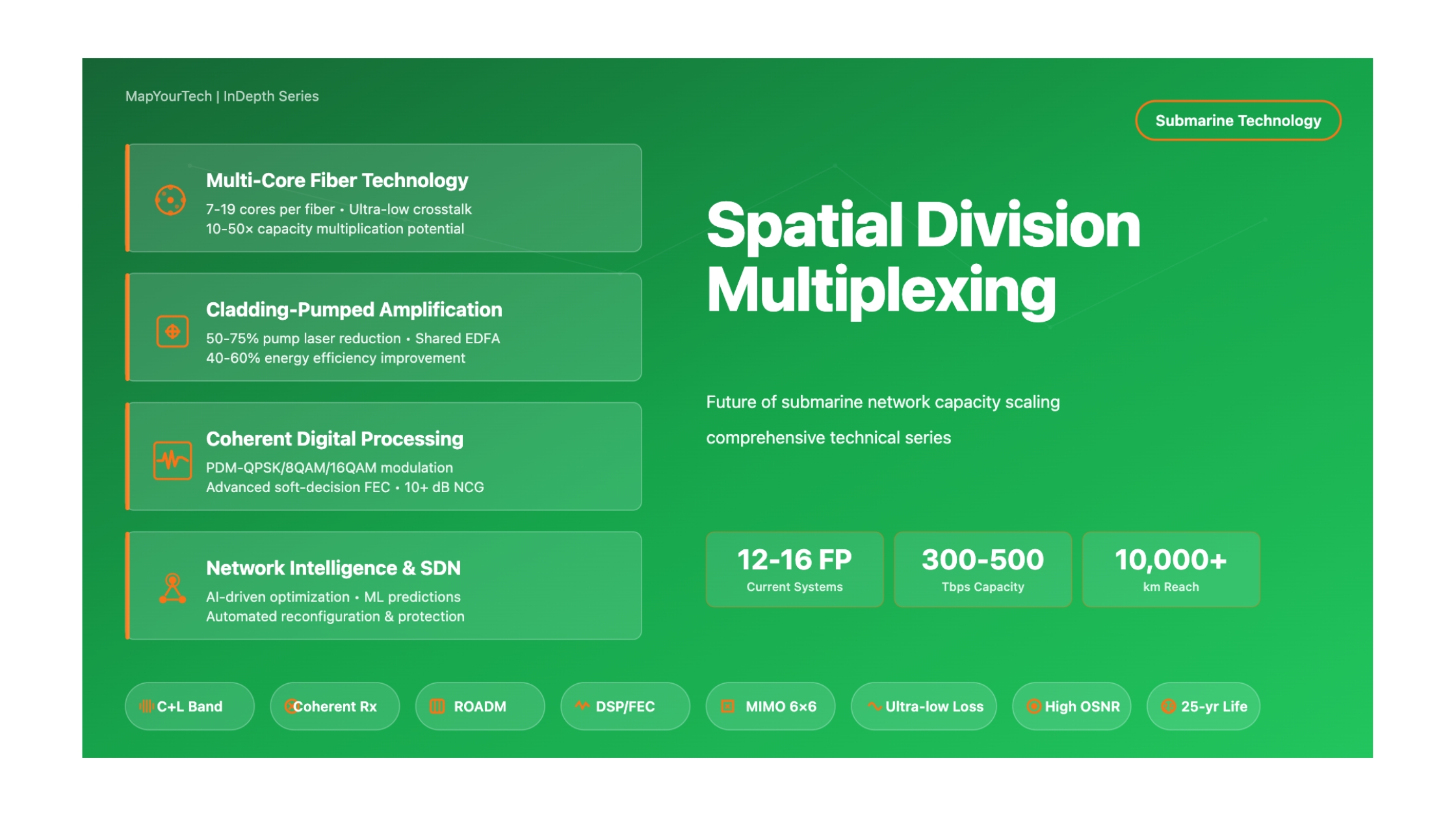
Spatial Division Multiplexing: Future of Submarine Network Capacity
Exploring the Next Generation of Transoceanic Communications Infrastructure
Introduction
The global internet infrastructure depends fundamentally on submarine fiber optic cables that traverse the world's oceans, connecting continents and enabling the seamless flow of information that defines modern society. These undersea systems carry approximately 99% of all intercontinental data traffic, supporting everything from financial transactions and cloud computing to video streaming and social media. As of 2025, nearly 1.5 million kilometers of submarine cables form the backbone of global telecommunications, with capacity demands growing exponentially year over year.
For decades, the submarine cable industry has addressed capacity growth through two primary approaches: wavelength division multiplexing (WDM) to increase the number of optical channels per fiber, and advanced modulation formats to pack more bits per second into each channel. The introduction of coherent detection technology around 2010 marked a revolutionary advancement, enabling capacity per wavelength to grow from 10 Gbps to 100 Gbps and eventually reaching 800 Gbps per wavelength in modern systems. However, despite these remarkable achievements, the industry now faces a fundamental challenge: the Shannon Limit, which defines the maximum information-carrying capacity of an optical fiber in the presence of noise and nonlinear impairments.
Spatial Division Multiplexing (SDM) represents a transformative approach to bypass these capacity constraints by expanding the spatial dimension of optical transmission. Rather than attempting to extract more capacity from individual optical fibers through increasingly complex modulation schemes, SDM increases the aggregate bandwidth of submarine cables by deploying significantly more fiber pairs within the same cable infrastructure. This seemingly straightforward solution introduces profound changes to submarine cable design, amplification systems, power distribution, and operational practices.
Key Insight
SDM submarine cables with 12 to 24 fiber pairs represent a fundamental shift from traditional 4 to 8 fiber pair systems, effectively multiplying total cable capacity by 2× to 4× while maintaining compatibility with existing coherent transceiver technology. This approach provides immediate capacity scaling without requiring revolutionary new optical transmission techniques.
The first commercial deployment of SDM technology in submarine systems occurred with Google's Dunant cable in 2020, which connected Virginia Beach in the United States to France across 6,600 kilometers of the Atlantic Ocean. This system demonstrated the viability of 12 fiber pair (FP) designs, achieving 250 Tbps total capacity (approximately 21 Tbps per fiber pair). Since then, multiple SDM submarine cables have been announced and deployed, including systems with 16 and 24 fiber pairs, marking the beginning of a new era in transoceanic communications.
Historical Context and Evolution
The Pre-SDM Era: From Single Wavelength to Dense WDM
The history of submarine cable capacity scaling provides essential context for understanding why SDM has emerged as the next evolutionary step. The first transoceanic optical fiber cable, TAT-8, began operation in 1988 connecting the United States and Europe. This pioneering system utilized intensity modulation with direct detection (IM-DD) technology, operating at 280 Mbps with two active fiber pairs plus one protection pair. While revolutionary for its time, TAT-8's capacity of approximately 40,000 simultaneous telephone circuits pales in comparison to modern submarine systems that can support millions of concurrent high-definition video streams.
The 1990s witnessed the introduction of optical amplification based on Erbium-Doped Fiber Amplifiers (EDFAs), which eliminated the need for expensive electronic regenerators and enabled much longer transmission distances. Early optically amplified systems operated at 5 Gbps per wavelength, representing a significant improvement over previous electronic regeneration systems. The predictable and stable gain characteristics of EDFAs, combined with their ability to amplify multiple wavelengths simultaneously, set the stage for the next major advancement: Wavelength Division Multiplexing.
The late 1990s and early 2000s saw rapid adoption of WDM technology in submarine systems. The SEA-ME-WE 3 cable, deployed in 1999, became one of the first major submarine systems to implement WDM with eight wavelengths at 2.5 Gbps each, providing approximately 20 Gbps of capacity per fiber pair. This system connected 33 countries across 39 landing stations, spanning approximately 40,000 kilometers from Northern Europe to Southeast Asia and extending to Australia. The economic efficiency of WDM technology proved compelling: rather than deploying entirely new submarine cables, operators could significantly increase capacity by upgrading terminal equipment while reusing the existing undersea infrastructure.
As WDM technology matured, both the number of wavelengths and the bit rate per wavelength increased dramatically. By the mid-2000s, submarine systems commonly deployed 40 to 80 wavelengths at 10 Gbps per channel, delivering aggregate capacities approaching 1 Tbps per fiber pair. These systems utilized sophisticated dispersion management techniques, combining positive dispersion fiber (PDF) with dispersion compensating fiber (DCF) to control chromatic dispersion effects that would otherwise limit transmission performance. The optical bandwidth of C-band EDFAs expanded from approximately 34 nanometers to 40 nanometers through improved gain flattening filter designs, enabling more wavelengths within the available spectrum.
The Coherent Revolution: Approaching the Shannon Limit
The introduction of coherent detection technology around 2010 marked the most significant advancement in submarine communications since the invention of the optical amplifier. Unlike direct detection systems that could only recover signal intensity information, coherent receivers capture the full optical field including amplitude, phase, and polarization components. This comprehensive signal reception enables sophisticated digital signal processing (DSP) algorithms to compensate for transmission impairments that previously required optical-domain solutions.
Coherent technology enabled multiple breakthrough capabilities simultaneously. First, polarization-division multiplexing (PDM) effectively doubled spectral efficiency by transmitting independent data streams on orthogonal polarization states. Second, phase modulation formats such as Quadrature Phase Shift Keying (QPSK) and Quadrature Amplitude Modulation (QAM) allowed encoding of multiple bits per symbol, dramatically increasing information density. Third, electronic dispersion compensation eliminated the need for dispersion compensating fiber in the undersea plant, simplifying cable design and reducing optical losses. These advances combined to increase spectral efficiency from approximately 0.2 bits/s/Hz with IM-DD technology to 4-6 bits/s/Hz with modern coherent systems.
The rapid evolution of coherent modem technology followed Moore's Law improvements in CMOS process technology. Advanced DSP implementations in 65nm, 45nm, and eventually 28nm CMOS enabled increasingly sophisticated algorithms including soft-decision forward error correction (SD-FEC), nonlinear compensation, and probabilistic constellation shaping (PCS). Commercial submarine systems deployed in the 2010s typically operated at 100 Gbps per wavelength using PDM-QPSK modulation, with more recent systems achieving 200 Gbps or higher using advanced modulation formats and coding schemes.
However, as coherent technology pushed spectral efficiencies ever closer to the theoretical Shannon Limit, the rate of capacity improvement began to slow. The Shannon Limit defines the maximum information rate that can be reliably transmitted through a communication channel with a given bandwidth and signal-to-noise ratio. For submarine optical fiber systems, this limit is influenced by fiber attenuation, amplifier noise, and nonlinear effects that occur at high optical power levels. Practical systems have achieved spectral efficiencies approaching 6-7 bits/s/Hz in laboratory experiments, but diminishing returns become evident: each incremental improvement requires exponentially more complex and power-hungry DSP implementations.
Shannon Capacity Formula for Submarine Cables
The theoretical capacity limit for optical fiber transmission can be expressed as: C = B × log₂(1 + SNR), where C is the channel capacity, B is the bandwidth (optical spectrum), and SNR is the signal-to-noise ratio. SDM addresses capacity growth by expanding B (the total available bandwidth) rather than attempting to further optimize SNR, which faces fundamental physical limitations.
Emergence of Spatial Division Multiplexing
The concept of Spatial Division Multiplexing emerged in the late 2000s as researchers recognized that continued capacity growth would require exploiting spatial dimensions in addition to wavelength and polarization. Professor Alan Chraplyvy of Bell Laboratories highlighted the approaching "capacity crunch" in a seminal 2009 presentation at the European Conference on Optical Communications, arguing that traditional scaling approaches would soon exhaust available options. This presentation catalyzed intensive research into SDM technologies, spawning numerous academic and industrial research programs worldwide.
Initial SDM research explored two primary technological approaches: multi-core fibers (MCF) and few-mode fibers (FMF). Multi-core fibers contain multiple independent light-guiding cores within a single 125-micrometer cladding diameter, similar to placing several conventional single-mode fibers side by side within a common glass structure. Few-mode fibers support multiple spatial modes within a single core, allowing transmission of independent data streams on different modes. Both approaches promised significant capacity multiplication, but they also introduced substantial technical challenges including inter-core crosstalk, mode coupling, and the need for complex multiple-input multiple-output (MIMO) signal processing.
For submarine applications, a more pragmatic form of SDM emerged: simply increasing the number of conventional single-mode fiber pairs within the submarine cable. This approach, sometimes called "bundled SDM" or "uncoupled SDM," offered several compelling advantages. It required no changes to existing coherent transceiver technology, avoided the complexity of MIMO processing, and leveraged mature fiber manufacturing processes. The primary challenges related to cable engineering (accommodating more fibers in limited cable cross-section), amplifier design (powering more fiber pairs with limited electrical power), and operational procedures (managing higher fiber counts during installation and maintenance).
Google's Dunant cable, completed in 2020, validated the bundled SDM approach for transoceanic applications. With 12 fiber pairs spanning 6,600 kilometers, the system achieved 250 Tbps total capacity while maintaining compatibility with standard coherent transceivers. The success of Dunant prompted rapid industry adoption, with numerous subsequent submarine cable projects specifying 12, 16, or even 24 fiber pairs. The 2Africa cable system, completed in 2025, deployed 16 fiber pairs across one of the world's longest submarine networks, connecting Africa, Europe, and the Middle East with unprecedented capacity.
Fundamental Concepts of Spatial Division Multiplexing
Defining Spatial Division Multiplexing
Spatial Division Multiplexing refers to techniques that increase optical transmission capacity by exploiting spatial dimensions beyond the single-core, single-mode paradigm that has dominated fiber optics for decades. In the submarine cable context, SDM most commonly means deploying cables with significantly more fiber pairs than traditional designs. Where conventional submarine cables typically contained 4 to 8 fiber pairs (with each pair consisting of one transmit fiber and one receive fiber), modern SDM cables incorporate 12 to 24 fiber pairs, with research exploring even higher counts.
The fundamental principle underlying SDM is straightforward: if individual optical fibers are approaching their theoretical capacity limits, aggregate cable capacity can continue to scale by deploying more parallel fibers. This approach sidesteps the Shannon Limit constraints that affect single-fiber transmission by expanding the total available optical bandwidth in the cable. Each additional fiber pair provides another independent optical transmission channel, with its own set of wavelengths and its own capacity potential. The total cable capacity becomes the sum of capacities across all fiber pairs.
Three distinct technological approaches fall under the SDM umbrella, each with different characteristics and maturity levels. Uncoupled multi-core fiber (MCF) integrates multiple independent cores within a single fiber cladding, typically maintaining sufficient core spacing (greater than 40 micrometers) to minimize crosstalk below -40 dB over transoceanic distances. Coupled multi-core fiber uses closer core spacing, accepting higher crosstalk levels but requiring complex MIMO signal processing to separate the coupled signals at the receiver. Few-mode fiber (FMF) supports multiple spatial modes within a single core, again requiring MIMO processing to demultiplex mode-multiplexed signals. For submarine applications deployed through 2025, the bundled fiber approach (simply using more conventional single-mode fibers) has proven most practical.
Key Enabling Technologies
Several technological developments have made SDM viable for submarine cable applications. Advances in fiber manufacturing have enabled production of ultra-low-loss fibers with attenuation approaching 0.150 dB/km at 1550 nm wavelength, compared to typical values of 0.185-0.190 dB/km for standard single-mode fiber. These pure-silica-core fibers (PSCF) also feature large effective areas (Aeff) of 110-150 square micrometers, which reduces nonlinear effects and enables higher optical power per channel. The combination of low loss and large effective area allows longer amplifier spacing and improved system margins, partially offsetting the challenges of powering more amplifiers in SDM systems.
Cable engineering innovations have been crucial for accommodating increased fiber counts within constrained cable diameters. Submarine cables face strict mechanical requirements including strength for deployment and recovery operations, flexibility for handling on cable ships, and protection against external hazards in the shallow water zone. Traditional submarine cables with 8 fiber pairs typically have diameters of 17-21 millimeters depending on the cable segment (lightweight, single-armored, or double-armored). SDM cables with 12-16 fiber pairs maintain similar external dimensions through several approaches: reducing fiber coating thickness from 200 micrometers to 200 micrometers or less, optimizing fiber stranding and tube designs, and improving cable strength member configurations. Some designs explore going to 250 micrometer diameter coated fibers to accommodate more fibers in limited space.
Power system design represents another critical enabler. Submarine cables include a copper or aluminum conductor that carries DC current from shore power feeding equipment (PFE) to power optical amplifiers in submerged repeaters. The available electrical power constrains the number of fiber pairs that can be supported, since each additional fiber pair typically requires an additional optical amplifier at each repeater location. Modern repeater designs have improved power efficiency through several mechanisms: cladding-pumped amplifier architectures that share pump lasers across multiple fibers, more efficient pump diodes and power converters, and optimized amplifier spacing that balances electrical power consumption against optical performance requirements.
Amplification Architecture for SDM Systems
Optical amplification in SDM submarine cables requires careful architectural consideration to balance performance, power consumption, and reliability. In traditional submarine repeaters, each fiber typically has a dedicated erbium-doped fiber amplifier (EDFA) with its own pump lasers. The pump lasers, operating at 980 nm or 1480 nm wavelength, excite erbium ions in the doped fiber to create optical gain. For an 8 fiber pair system, a repeater might contain 16 individual EDFAs (one per fiber direction), each with 2-4 pump diodes, resulting in 32-64 pump lasers per repeater.
SDM systems with 12-24 fiber pairs would require proportionally more amplifiers and pump lasers if designed using conventional single-fiber amplification. However, this approach would exceed power budgets and create excessive component count. Instead, advanced amplification architectures leverage pump sharing and cladding-pumped designs. In a cladding-pumped multi-fiber amplifier, a single high-power pump laser couples into the common inner cladding surrounding multiple erbium-doped fiber cores. The pump light propagates in the cladding and is gradually absorbed by the doped cores, providing gain to multiple signal fibers simultaneously. This architecture dramatically reduces the number of required pump lasers and associated power consumption.
Pump farming techniques further optimize power efficiency by allowing pump resources to be shared dynamically across fiber pairs based on actual traffic loading. Rather than dedicating fixed pump power to each fiber, a pool of pumps can be allocated where needed, improving overall efficiency when not all fiber pairs operate at maximum capacity simultaneously. This flexibility proves valuable during phased capacity growth, where initial traffic may use only a subset of available fiber pairs, with additional fiber pairs activated as demand grows.
Read the Full Analysis with Premium
The remaining 89% of this article — the design numbers, trade-offs and field guidance — is part of MapYourTech Premium, along with the full premium library, courses and professional tools.
You May Also Like

-
Free
-
September 4, 2026

-
Premium
-
September 4, 2026

-
Premium
-
September 4, 2026