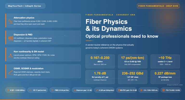
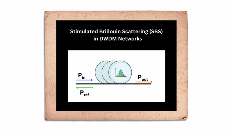
Tag

Optical fiber

Browsing

Optical networks are the backbone of the internet, carrying vast amounts of data over great distances at the speed of light. However, maintaining signal quality over long fiber runs is a challenge due to a phenomenon known as noise concatenation. Let’s delve into how amplified spontaneous emission (ASE) noise affects Optical Signal-to-Noise Ratio (OSNR) and the performance of optical amplifier chains.

The Challenge of ASE Noise

ASE noise is an inherent byproduct of optical amplification, generated by the spontaneous emission of photons within an optical amplifier. As an optical signal traverses through a chain of amplifiers, ASE noise accumulates, degrading the OSNR with each subsequent amplifier in the chain. This degradation is a crucial consideration in designing long-haul optical transmission systems.

Understanding OSNR

OSNR measures the ratio of signal power to ASE noise power and is a critical parameter for assessing the performance of optical amplifiers. A high OSNR indicates a clean signal with low noise levels, which is vital for ensuring data integrity.

Reference System for OSNR Estimation

As depicted in Figure below), a typical multichannel N span system includes a booster amplifier, N−1 line amplifiers, and a preamplifier. To simplify the estimation of OSNR at the receiver’s input, we make a few assumptions:

Representation of optical line system interfaces (a multichannel N-span system)
  • All optical amplifiers, including the booster and preamplifier, have the same noise figure.
  • The losses of all spans are equal, and thus, the gain of the line amplifiers compensates exactly for the loss.
  • The output powers of the booster and line amplifiers are identical.

Estimating OSNR in a Cascaded System

E1: Master Equation For OSNR

E1: Master Equation For OSNR

Pout is the output power (per channel) of the booster and line amplifiers in dBm, L is the span loss in dB (which is assumed to be equal to the gain of the line amplifiers), GBA is the gain of the optical booster amplifier in dB, NFis the signal-spontaneous noise figure of the optical amplifier in dB, h is Planck’s constant (in mJ·s to be consistent with Pout in dBm), ν is the optical frequency in Hz, νr is the reference bandwidth in Hz (corresponding to c/Br ), N–1 is the total number of line amplifiers.

The OSNR at the receivers can be approximated by considering the output power of the amplifiers, the span loss, the gain of the optical booster amplifier, and the noise figure of the amplifiers. Using constants such as Planck’s constant and the optical frequency, we can derive an equation that sums the ASE noise contributions from all N+1 amplifiers in the chain.

Simplifying the Equation

Under certain conditions, the OSNR equation can be simplified. If the booster amplifier’s gain is similar to that of the line amplifiers, or if the span loss greatly exceeds the booster gain, the equation can be modified to reflect these scenarios. These simplifications help network designers estimate OSNR without complex calculations.

1)          If the gain of the booster amplifier is approximately the same as that of the line amplifiers, i.e., GBA » L, above Equation E1 can be simplified to:

osnr_2

E1-1

2)          The ASE noise from the booster amplifier can be ignored only if the span loss L (resp. the gain of the line amplifier) is much greater than the booster gain GBA. In this case Equation E1-1 can be simplified to:

E1-2

3)          Equation E1-1 is also valid in the case of a single span with only a booster amplifier, e.g., short‑haul multichannel IrDI in Figure 5-5 of [ITU-T G.959.1], in which case it can be modified to:

E1-3

4)          In case of a single span with only a preamplifier, Equation E1 can be modified to:

Practical Implications for Network Design

Understanding the accumulation of ASE noise and its impact on OSNR is crucial for designing reliable optical networks. It informs decisions on amplifier placement, the necessity of signal regeneration, and the overall system architecture. For instance, in a system where the span loss is significantly high, the impact of the booster amplifier on ASE noise may be negligible, allowing for a different design approach.

Conclusion

Noise concatenation is a critical factor in the design and operation of optical networks. By accurately estimating and managing OSNR, network operators can ensure signal quality, minimize error rates, and extend the reach of their optical networks.

In a landscape where data demands are ever-increasing, mastering the intricacies of noise concatenation and OSNR is essential for anyone involved in the design and deployment of optical communication systems.

References

https://www.itu.int/rec/T-REC-G/e

In the realm of telecommunications, the precision and reliability of optical fibers and cables are paramount. The International Telecommunication Union (ITU) plays a crucial role in this by providing a series of recommendations that serve as global standards. The ITU-T G.650.x and G.65x series of recommendations are especially significant for professionals in the field. In this article, we delve into these recommendations and their interrelationships, as illustrated in Figure 1 .

ITU-T G.650.x Series: Definitions and Test Methods

#opticalfiber

The ITU-T G.650.x series is foundational for understanding single-mode fibers and cables. ITU-T G.650.1 is the cornerstone, offering definitions and test methods for linear and deterministic parameters of single-mode fibers. This includes key measurements like attenuation and chromatic dispersion, which are critical for ensuring fiber performance over long distances.

Moving forward, ITU-T G.650.2 expands on the initial parameters by providing definitions and test methods for statistical and non-linear parameters. These are essential for predicting fiber behavior under varying signal powers and during different transmission phenomena.

For those involved in assessing installed fiber links, ITU-T G.650.3 offers valuable test methods. It’s tailored to the needs of field technicians and engineers who analyze the performance of installed single-mode fiber cable links, ensuring that they meet the necessary standards for data transmission.

ITU-T G.65x Series: Specifications for Fibers and Cables

The ITU-T G.65x series recommendations provide specifications for different types of optical fibers and cables. ITU-T G.651.1 targets the optical access network with specifications for 50/125 µm multimode fiber and cable, which are widely used in local area networks and data centers due to their ability to support high data rates over short distances.

The series then progresses through various single-mode fiber specifications:

  • ITU-T G.652: The standard single-mode fiber, suitable for a wide range of applications.
  • ITU-T G.653: Dispersion-shifted fibers optimized for minimizing chromatic dispersion.
  • ITU-T G.654: Features a cut-off shifted fiber, often used for submarine cable systems.
  • ITU-T G.655: Non-zero dispersion-shifted fibers, which are ideal for long-haul transmissions.
  • ITU-T G.656: Fibers designed for a broader range of wavelengths, expanding the capabilities of dense wavelength division multiplexing systems.
  • ITU-T G.657: Bending loss insensitive fibers, offering robust performance in tight bends and corners.

Historical Context and Current References

It’s noteworthy to mention that the multimode fiber test methods were initially described in ITU-T G.651. However, this recommendation was deleted in 2008, and now the test methods for multimode fibers are referenced in existing IEC documents. Professionals seeking current standards for multimode fiber testing should refer to these IEC documents for the latest guidelines.

Conclusion

The ITU-T recommendations play a critical role in the standardization and performance optimization of optical fibers and cables. By adhering to these standards, industry professionals can ensure compatibility, efficiency, and reliability in fiber optic networks. Whether you are a network designer, a field technician, or an optical fiber manufacturer, understanding these recommendations is crucial for maintaining the high standards expected in today’s telecommunication landscape.

Reference

https://www.itu.int/rec/T-REC-G/e

Optical Fiber technology is a game-changer in the world of telecommunication. It has revolutionized the way we communicate and share information. Fiber optic cables are used in most high-speed internet connections, telephone networks, and cable television systems.


What is Fiber Optic Technology?

Fiber optic technology is the use of thin, transparent fibers of glass or plastic to transmit light signals over long distances. These fibers are used in telecommunications to transmit data, video, and voice signals at high speeds and over long distances.

What are Fiber Optic Cables Made Of?

Fiber optic cables are made of thin strands of glass or plastic called fibers. These fibers are surrounded by protective coatings, which make them resistant to moisture, heat, and other environmental factors.

How Does Fiber Optic Technology Work?

Fiber optic technology works by sending pulses of light through the fibers in a cable. These light signals travel through the cable at very high speeds, allowing data to be transmitted quickly and efficiently.

What is an Optical Network?

An optical network is a communication network that uses optical fibers as the primary transmission medium. Optical networks are used for high-speed internet connections, telephone networks, and cable television systems.

What are the Benefits of Fiber Optic Technology?

Fiber optic technology offers several benefits over traditional copper wire technology, including:

  • Faster data transfer speeds
  • Greater bandwidth capacity
  • Less signal loss
  • Resistance to interference from electromagnetic sources
  • Greater reliability
  • Longer lifespan

How Fast is Fiber Optic Internet?

Fiber optic internet can provide download speeds of up to 1 gigabit per second (Gbps) and upload speeds of up to 1 Gbps. This is much faster than traditional copper wire internet connections.

How is Fiber Optic Internet Installed?

Fiber optic internet is installed by running fiber optic cables from a central hub to the homes or businesses that need internet access. The installation process involves digging trenches to bury the cables or running the cables overhead on utility poles.

What are the Different Types of Fiber Optic Cables?

There are two main types of fiber optic cables:

Single-Mode Fiber

Single-mode fiber has a smaller core diameter than multi-mode fiber, which allows it to transmit light signals over longer distances with less attenuation.

Multi-Mode Fiber

Multi-mode fiber has a larger core diameter than single-mode fiber, which allows it to transmit light signals over shorter distances at a lower cost.

What is the Difference Between Single-Mode and Multi-Mode Fiber?

The main difference between single-mode and multi-mode fiber is the size of the core diameter. Single-mode fiber has a smaller core diameter, which allows it to transmit light signals over longer distances with less attenuation. Multi-mode fiber has a larger core diameter, which allows it to transmit light signals over shorter distances at a lower cost.

What is the Maximum Distance for Fiber Optic Cables?

The maximum distance for fiber optic cables depends on the type of cable and the transmission technology used. In general, single-mode fiber can transmit light signals over distances of up to 10 kilometers without the need for signal regeneration, while multi-mode fiber is limited to distances of up to 2 kilometers.

What is Fiber Optic Attenuation?

Fiber optic attenuation refers to the loss of light signal intensity as it travels through a fiber optic cable. Attenuation is caused by factors such as absorption, scattering, and bending of the light signal.

What is Fiber Optic Dispersion?

Fiber optic dispersion refers to the spreading of a light signal as it travels through a fiber optic cable. Dispersion is caused by factors such as the wavelength of the light signal and the length of the cable.

What is Fiber Optic Splicing?

Fiber optic splicing is the process of joining two fiber optic cables together. Splicing is necessary when extending the length of a fiber optic cable or when repairing a damaged cable.

What is the Difference Between Fusion Splicing and Mechanical Splicing?

Fusion splicing is a process in which the two fibers to be joined are fused together using heat. Mechanical splicing is a process in which the two fibers to be joined are aligned and held together using a mechanical splice.

What is Fiber Optic Termination?

Fiber optic termination is the process of connecting a fiber optic cable to a device or equipment. Termination involves attaching a connector to the end of the cable so that it can be plugged into a device or equipment.

What is an Optical Coupler?

An optical coupler is a device that splits or combines light signals in a fiber optic network. Couplers are used to distribute signals from a single source to multiple destinations or to combine signals from multiple sources into a single fiber.

What is an Optical Splitter?

optical splitter is a type of optical coupler that splits a single fiber into multiple fibers. Splitters are used to distribute signals from a single source to multiple destinations.

What is Wavelength-Division Multiplexing?

Wavelength-division multiplexing is a technology that allows multiple signals of different wavelengths to be transmitted over a single fiber. Each signal is assigned a different wavelength, and a multiplexer is used to combine the signals into a single fiber.

What is Dense Wavelength-Division Multiplexing?

Dense wavelength-division multiplexing is a technology that allows multiple signals to be transmitted over a single fiber using very closely spaced wavelengths. DWDM is used to increase the capacity of fiber optic networks.

What is Coarse Wavelength-Division Multiplexing?

Coarse wavelength-division multiplexing is a technology that allows multiple signals to be transmitted over a single fiber using wider-spaced wavelengths than DWDM. CWDM is used for shorter distance applications and lower bandwidth requirements.

What is Bidirectional Wavelength-Division Multiplexing?

Bidirectional wavelength-division multiplexing is a technology that allows signals to be transmitted in both directions over a single fiber. BIDWDM is used to increase the capacity of fiber optic networks.

What is Fiber Optic Testing?

Fiber optic testing is the process of testing the performance of fiber optic cables and components. Testing is done to ensure that the cables and components meet industry standards and to troubleshoot problems in the network.

What is Optical Time-Domain Reflectometer?

An optical time-domain reflectometer is a device used to test fiber optic cables by sending a light signal into the cable and measuring the reflections. OTDRs are used to locate breaks, bends, and other faults in fiber optic cables.

What is Optical Spectrum Analyzer?

An optical spectrum analyzer is a device used to measure the spectral characteristics of a light signal. OSAs are used to analyze the output of fiber optic transmitters and to measure the characteristics of fiber optic components.

What is Optical Power Meter?

An optical power meter is a device used to measure the power of a light signal in a fiber optic cable. Power meters are used to measure the output of fiber optic transmitters and to test the performance of fiber optic cables and components.

What is Fiber Optic Connector?

A fiber optic connector is a device used to attach a fiber optic cable to a device or equipment. Connectors are designed to be easily plugged and unplugged, allowing for easy installation and maintenance.

What is Fiber Optic Adapter?

A fiber optic adapter is a device used to connect two fiber optic connectors together. Adapters are used to extend the length of a fiber optic cable or to connect different types of fiber optic connectors.

What is Fiber Optic Patch Cord?

A fiber optic patch cord is a cable with connectors on both ends used to connect devices or equipment in a fiber optic network. Patch cords are available in different lengths and connector types to meet different network requirements.

What is Fiber Optic Pigtail?

A fiber optic pigtail is a short length of fiber optic cable with a connector on one end and a length of exposed fiber on the other. Pigtails are used to connect fiber optic cables to devices or equipment that require a different type of connector.

What is Fiber Optic Coupler?

A fiber optic coupler is a device used to split or combine light signals in a fiber optic network. Couplers are used to distribute signals from a single source to multiple destinations or to combine signals from multiple sources into a single fiber.

What is Fiber Optic Attenuator?

A fiber optic attenuator is a device used to reduce the power of a light signal in a fiber optic network. Attenuators are used to prevent

signal overload or to match the power levels of different components in the network.

What is Fiber Optic Isolator?

A fiber optic isolator is a device used to prevent light signals from reflecting back into the source. Isolators are used to protect sensitive components in the network from damage caused by reflected light.

What is Fiber Optic Circulator?

A fiber optic circulator is a device used to route light signals in a specific direction in a fiber optic network. Circulators are used to route signals between multiple devices in a network.

What is Fiber Optic Amplifier?

A fiber optic amplifier is a device used to boost the power of a light signal in a fiber optic network. Amplifiers are used to extend the distance that a signal can travel without the need for regeneration.

What is Fiber Optic Modulator?

A fiber optic modulator is a device used to modulate the amplitude or phase of a light signal in a fiber optic network. Modulators are used in applications such as fiber optic communication and sensing.

What is Fiber Optic Switch?

A fiber optic switch is a device used to switch light signals between different fibers in a fiber optic network. Switches are used to route signals between multiple devices in a network.

What is Fiber Optic Demultiplexer?

A fiber optic demultiplexer is a device used to separate multiple signals of different wavelengths that are combined in a single fiber. Demultiplexers are used in wavelength-division multiplexing applications.

What is Fiber Optic Multiplexer?

A fiber optic multiplexer is a device used to combine multiple signals of different wavelengths into a single fiber. Multiplexers are used in wavelength-division multiplexing applications.

What is Fiber Optic Transceiver?

A fiber optic transceiver is a device that combines a transmitter and a receiver into a single module. Transceivers are used to transmit and receive data over a fiber optic network.

What is Fiber Optic Media Converter?

A fiber optic media converter is a device used to convert a fiber optic signal to a different format, such as copper or wireless. Media converters are used to connect fiber optic networks to other types of networks.

What is Fiber Optic Splice Closure?

A fiber optic splice closure is a device used to protect fiber optic splices from environmental factors such as moisture and dust. Splice closures are used in outdoor fiber optic applications.

What is Fiber Optic Distribution Box?

A fiber optic distribution box is a device used to distribute fiber optic signals to multiple devices or equipment. Distribution boxes are used in fiber optic networks to route signals between multiple devices.

What is Fiber Optic Patch Panel?

A fiber optic patch panel is a device used to connect multiple fiber optic cables to a network. Patch panels are used to organize and manage fiber optic connections in a network.

What is Fiber Optic Cable Tray?

A fiber optic cable tray is a device used to support and protect fiber optic cables in a network. Cable trays are used to organize and route fiber optic cables in a network.

What is Fiber Optic Duct?

A fiber optic duct is a device used to protect fiber optic cables from environmental factors such as moisture and dust. Ducts are used in outdoor fiber optic applications.

What is Fiber Optic Raceway?

A fiber optic raceway is a device used to route and protect fiber optic cables in a network. Raceways are used to organize and manage fiber optic connections in a network.

What is Fiber Optic Conduit?

A fiber optic conduit is a protective tube used to house fiber optic cables in a network. Conduits are used in outdoor fiber optic applications to protect cables from environmental factors.

Non-linear interactions between the signal and the silica fibre transmission medium begin to appear as optical signal powers are increased to achieve longer span lengths at high bit rates. Consequently, non-linear fibre behaviour has emerged as an important consideration both in high capacity systems and in long unregenerated routes. These non-linearities can be generally categorized as either scattering effects (stimulated Brillouin scattering and stimulated Raman scattering) or effects related to the fibre’s intensity dependent index of refraction (self-phase modulation, cross-phase modulation, modulation instability, soliton formation and four-wave mixing). A variety of parameters influence the severity of these non-linear effects, including line code (modulation format), transmission rate, fibre dispersion characteristics, the effective area and non-linear refractive index of the fibre, the number and spacing of channels in multiple channel systems, overall unregenerated system length, as well as signal intensity and source line-width. Since the implementation of transmission systems with higher bit rates than 10 Gbit/s and alternative line codes (modulation formats) than NRZ-ASK or RZ-ASK, described in [b-ITU-T G-Sup.39], non‑linear fibre effects previously not considered can have a significant influence, e.g., intra‑channel cross-phase modulation (IXPM), intra-channel four-wave mixing (IFWM) and non‑linear phase noise (NPN).