
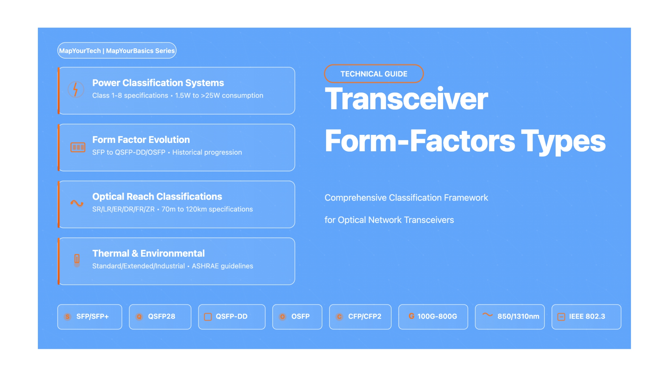

Comprehensive Guide to Transceiver Form-Factors Types in Optical Networking
A Technical Deep Dive into Power Classifications, Form Factors, Optical Specifications, and Industry Standards for High-Performance Fiber Optic Communication Systems
Introduction
The optical networking landscape has undergone a remarkable transformation over the past two decades, driven by exponentially increasing bandwidth demands from cloud computing, artificial intelligence, 5G networks, and streaming services. At the heart of this evolution lies the optical transceiver—a sophisticated electro-optical device that converts electrical signals to optical signals for transmission over fiber optic cables, and vice versa. Understanding transceiver classifications has become essential for network architects, telecommunications engineers, and data center operators who must design, deploy, and maintain high-performance optical communication systems.
Optical transceivers are classified according to multiple interdependent criteria that reflect their operational characteristics, physical attributes, and application domains. These classification systems have evolved alongside technological advancements, creating a complex taxonomy that encompasses form factors, power consumption classes, transmission distances, data rates, wavelength specifications, and fiber compatibility. The standardization of these classifications through Multi-Source Agreements and industry bodies such as IEEE, the Optical Internetworking Forum, and various MSA groups has enabled interoperability across equipment from different manufacturers while fostering competitive markets that drive innovation and cost reduction.
This comprehensive technical guide examines the multifaceted classification systems that define modern optical transceivers. From the compact Small Form-factor Pluggable modules that revolutionized 1G and 10G networks to the high-density QSFP-DD and OSFP form factors enabling 400G and 800G data center interconnects, each transceiver class represents careful engineering trade-offs between power consumption, thermal management, port density, reach capabilities, and cost. The guide explores how power class designations—ranging from Class 1 modules consuming 1.5 watts to Class 8 modules exceeding 14 watts—directly influence system design considerations including cooling infrastructure, power supply specifications, and host board capabilities.
Beyond form factors and power classifications, optical transceivers are distinguished by their transmission characteristics. The industry-standard reach designations—SR (Short Range), LR (Long Range), ER (Extended Range), DR (Data center Range), FR (Fast Range), and ZR (extended ZR)—define operational parameters that determine appropriate deployment scenarios. These classifications correlate with specific wavelength allocations, typically 850nm for multimode fiber applications and 1310nm or 1550nm for single-mode fiber deployments, each optimized for particular fiber attenuation characteristics and dispersion profiles. Modern coherent transceivers implementing 400ZR and 800ZR standards represent the cutting edge, enabling metro and long-haul transmission exceeding 120 kilometers through advanced digital signal processing techniques.
Key Classification Dimensions
Form Factor Families: The physical packaging determines port density and thermal characteristics, ranging from SFP/SFP+ for lower-speed applications through QSFP variants for 40G-400G deployments to emerging standards for 800G and 1.6T.
Power Classifications: Hierarchical power classes from 1.5W to beyond 14W enable system designers to match transceiver capabilities with cooling infrastructure and power budget constraints while supporting diverse reach and performance requirements.
Transmission Distance Categories: Standardized reach designations align with specific application requirements, from intra-rack connectivity to campus, metro, and long-haul telecommunications networks.
Data Rate Evolution: Classifications span from legacy 1G interfaces through contemporary 100G, 200G, and 400G standards to emerging 800G and 1.6T specifications that will define next-generation network architectures.
The intersection of these classification dimensions creates a rich design space where network engineers must evaluate multiple parameters simultaneously. A data center architect selecting transceivers for a spine-leaf topology must consider not only bandwidth requirements and reach capabilities but also power density limitations, airflow characteristics, port density objectives, and interoperability with existing infrastructure. Similarly, telecommunications operators deploying metro networks must balance cost-per-bit economics against reliability requirements, environmental specifications, and compatibility with wavelength division multiplexing systems.
Contemporary transceiver evolution reflects broader trends in optical networking including the transition from non-return-to-zero modulation schemes to pulse amplitude modulation PAM4 encoding, enabling doubled symbol rates for given electrical bandwidths. The emergence of coherent detection technologies in pluggable form factors has democratized sophisticated DSP-based transmission techniques previously reserved for line-side equipment. Linear Pluggable Optics represent another inflection point, relocating signal processing from transceivers to host application-specific integrated circuits to reduce power consumption and latency for datacenter applications where reach requirements are modest.
This guide provides network professionals with comprehensive technical knowledge necessary to navigate the complex landscape of transceiver classifications. Through detailed examination of industry standards, power consumption characteristics, optical specifications, and practical deployment considerations, readers will develop the expertise to select appropriate transceiver classes for diverse application requirements. The material addresses both established technologies deployed in production networks and emerging standards that will shape future optical communication systems, providing a foundation for informed decision-making in network design, procurement, and operations.
Understanding transceiver classifications extends beyond technical specifications to encompass supply chain considerations, vendor qualification processes, and lifecycle management strategies. The standardization achieved through MSA agreements enables robust multi-vendor ecosystems where operators can source compatible modules from numerous suppliers, mitigating supply chain risks while enabling competitive procurement. However, this interoperability requires careful attention to compatibility matrices, firmware management, and qualification testing to ensure reliable operations across diverse equipment combinations.
The rise of Pluggable Optical Transceivers
The history of optical transceiver classification is intrinsically linked to the evolution of pluggable form factors—a technological progression driven by relentless demands for higher bandwidth, greater port density, and reduced power consumption. The narrative begins in the mid-1990s when optical networking equipment required permanent soldered optical interfaces, creating significant maintenance challenges and limiting deployment flexibility. The introduction of the first standardized hot-pluggable transceiver marked a watershed moment, establishing principles that would govern optical interface design for decades to come.
The Gigabit Interface Converter, introduced in the late 1990s, represented the first widely adopted pluggable optical transceiver standard. Developed through collaboration among multiple equipment manufacturers, GBIC modules enabled 1 Gigabit per second transmission over fiber optic cables using SC optical connectors. The GBIC form factor measured approximately 31mm wide by 94mm deep, accommodating both multimode and single-mode fiber interfaces with reach capabilities spanning 550 meters to 100 kilometers depending on wavelength and fiber type. This standardization achieved through Multi-Source Agreement methodologies established critical precedents including hot-pluggability, standardized electrical interfaces, and vendor interoperability that would characterize subsequent transceiver generations.
Read the Full Analysis with Premium
The remaining 89% of this article — the design numbers, trade-offs and field guidance — is part of MapYourTech Premium, along with the full premium library, courses and professional tools.



Course Title
Course description and key highlights