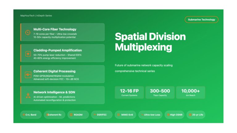
Spatial Division Multiplexing: Future of Submarine Network Capacity Spatial Division Multiplexing: Future of Submarine Network Capacity Exploring the Next Generation...
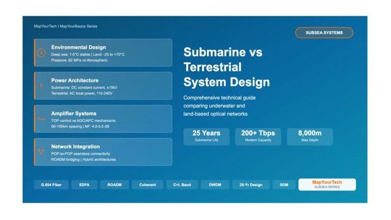
Submarine vs Terrestrial System Design Differences – Comprehensive Visual Guide Submarine vs Terrestrial System Design Differences Practical Information Based on...
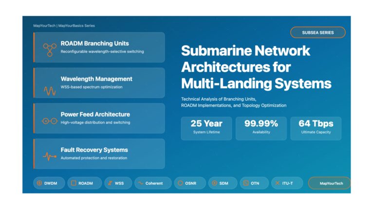
Advanced Deep Dive: Submarine Network Architectures for Multi-Landing Systems Advanced Deep Dive: Submarine Network Architectures for Multi-Landing Systems Technical Analysis...
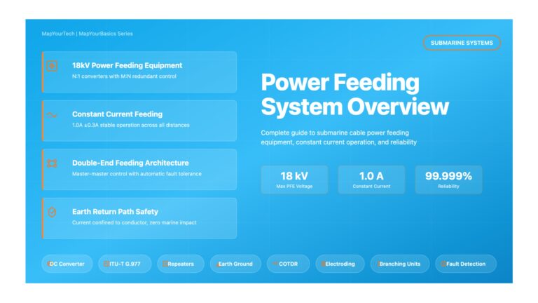
Power Feeding System Overview – Comprehensive Visual Guide Power Feeding System Overview Power Feeding Equipment (PFE) Practical Information Based on...