28 min read

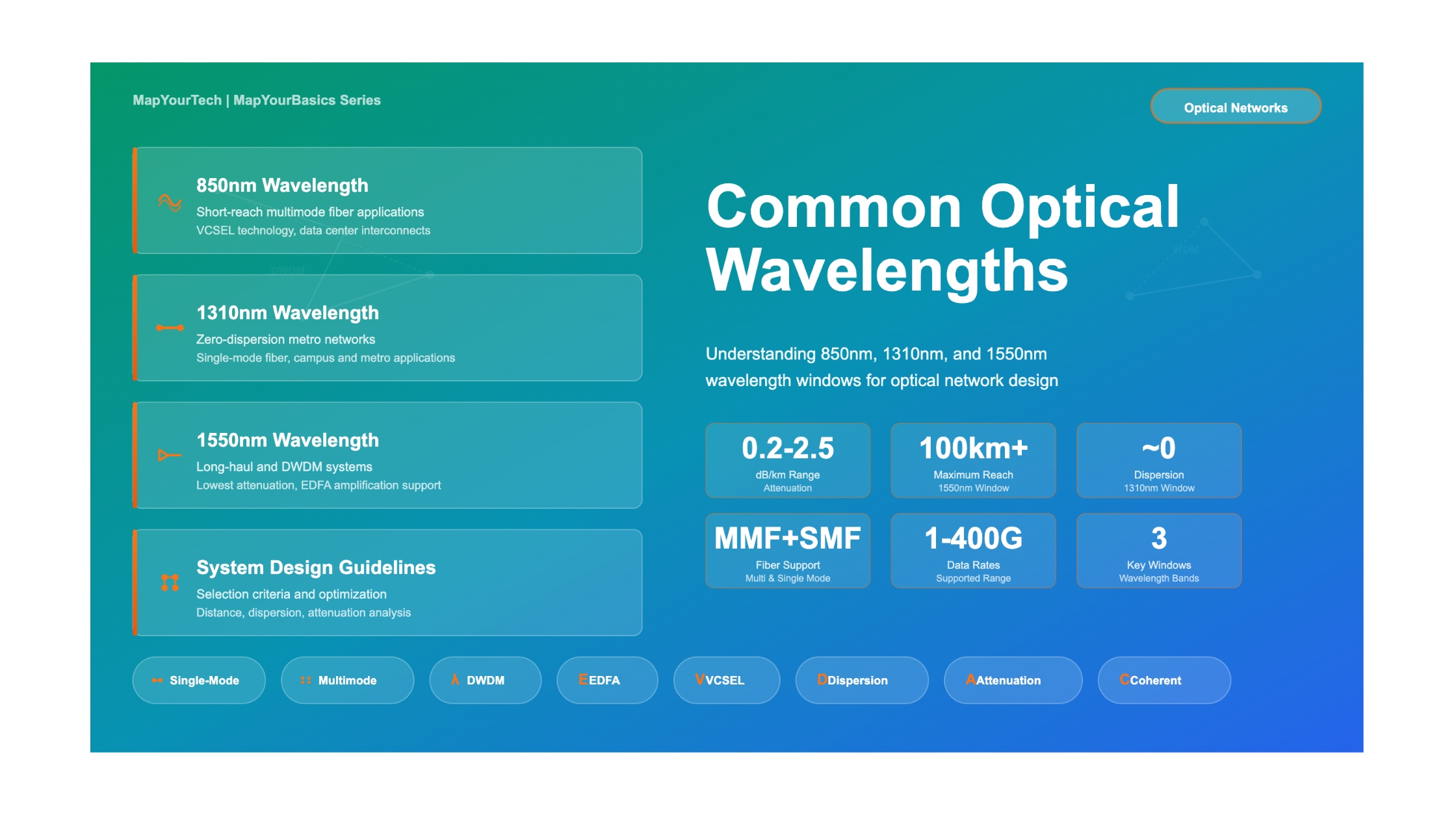
Common Optical Wavelengths: 850nm, 1310nm, 1550nm
Introduction
Optical fiber communication systems use specific wavelength windows in the electromagnetic spectrum to transmit data over fiber optic cables. These wavelengths are not chosen randomly – they represent carefully selected regions where optical fibers have optimal transmission characteristics. The three most common wavelengths used in modern optical networks are 850 nanometers (nm), 1310nm, and 1550nm. Each wavelength window has distinct physical properties, advantages, limitations, and ideal use cases that make it suitable for particular applications.
Understanding these wavelength windows is critical for network engineers, system architects, and technical professionals involved in designing, deploying, or maintaining optical networks. The choice of wavelength affects transmission distance, data rate, fiber type, equipment cost, power budget, and overall system performance. A wrong wavelength choice can result in poor signal quality, limited reach, higher costs, or incompatibility with existing infrastructure.
This guide provides a comprehensive analysis of the three primary optical wavelengths, examining their physical properties, technical specifications, attenuation characteristics, dispersion behavior, practical applications, and deployment scenarios. Whether you are planning a data center interconnect, designing a metropolitan area network, or engineering a long-haul transmission system, understanding these wavelength windows will help you make better technical decisions.
Key Takeaways
- 850nm is primarily used for short-reach multimode fiber applications in data centers and campus networks, supporting distances up to 550 meters with cost-effective VCSEL technology
- 1310nm operates at the zero-dispersion point of standard single-mode fiber, making it ideal for metro applications covering 2-40 kilometers without dispersion compensation
- 1550nm offers the lowest attenuation in optical fiber and enables long-haul transmission beyond 80 kilometers, supporting DWDM systems and optical amplification
- Wavelength selection depends on multiple factors including required distance, fiber type, data rate, cost constraints, and existing infrastructure
- Each wavelength window has specific technical characteristics that make it optimal for particular network segments and applications
1. Understanding Optical Wavelength Fundamentals
What is Optical Wavelength?
Wavelength represents the distance between consecutive peaks or troughs of a light wave, typically measured in nanometers (nm) for optical communications. In optical fiber systems, wavelength determines how light propagates through the fiber core, how much it attenuates over distance, and how various impairments affect signal quality. The wavelength of light is inversely related to its frequency through the relationship: wavelength = speed of light / frequency.
Optical fiber communication uses near-infrared wavelengths because these regions offer favorable transmission characteristics in silica glass fiber. The electromagnetic spectrum contains many wavelengths, but only specific windows in the near-infrared region (700nm to 1700nm) are practical for fiber optic transmission due to material properties of silica glass.
Why These Specific Wavelengths?
The selection of 850nm, 1310nm, and 1550nm as the primary wavelengths for optical communications is not arbitrary. These wavelengths correspond to regions where silica optical fiber exhibits favorable transmission characteristics, specifically low attenuation and manageable dispersion. The development of practical laser sources and photodetectors at these wavelengths, combined with standardization efforts by IEEE and ITU-T, has established these as the dominant wavelengths in commercial optical systems.
The 850nm wavelength window was the first to be commercially exploited because early semiconductor lasers and LEDs could operate at this wavelength with reasonable efficiency. The 1310nm window became popular when it was discovered that standard single-mode fiber has zero chromatic dispersion at this wavelength, enabling higher data rates without dispersion compensation. The 1550nm window gained prominence when it was found to have the lowest attenuation in optical fiber, making it ideal for long-distance transmission.
Fiber Optic Transmission Windows
Optical fiber has several transmission windows where light can propagate with acceptable loss characteristics. These windows are defined by regions of low attenuation in the optical fiber. The original three windows are:
- First Window (850nm): The earliest window used for fiber optic communications, centered around 850nm. This window has higher attenuation compared to longer wavelengths but was the first to have commercially available laser sources. It remains popular for short-distance multimode fiber applications.
- Second Window (1310nm): Discovered to have lower attenuation than the first window and, more importantly, to be the zero-dispersion wavelength for standard single-mode fiber. This makes it ideal for metro-distance applications where dispersion would otherwise limit performance.
- Third Window (1550nm): Has the lowest attenuation of all wavelengths in silica fiber, approximately 0.2 dB/km. This window enables ultra-long-haul transmission and is the preferred wavelength for DWDM systems. It also coincides with the gain region of Erbium-Doped Fiber Amplifiers (EDFAs).
Additional windows at 1260-1360nm (E-band) and extended C-band and L-band regions around 1550nm have been developed to increase capacity in DWDM systems, but the three primary windows remain the foundation of optical networking.
2. The 850nm Window: Short Reach and Data Centers
Physical Properties and Technology
The 850nm wavelength window represents the shortest wavelength commonly used in fiber optic communications. This window operates in the near-infrared region and was the first to be commercially developed for optical communications. The physical properties of 850nm light and its interaction with optical fiber make it well-suited for short-distance, high-speed data transmission in controlled environments like data centers.
Light sources at 850nm typically use Vertical-Cavity Surface-Emitting Lasers (VCSELs), which are semiconductor lasers that emit light perpendicular to the chip surface. VCSELs are much less expensive to manufacture than edge-emitting lasers, consume less power, and can be easily packaged into arrays for parallel optics. These characteristics make 850nm transceivers the most cost-effective option for short-reach applications.
Fiber Type and Propagation Characteristics
The 850nm window is almost exclusively used with multimode fiber (MMF), which has a larger core diameter (50 or 62.5 micrometers) compared to single-mode fiber. Multimode fiber allows multiple light modes (paths) to propagate simultaneously through the fiber core. While this larger core makes alignment and connection easier and more forgiving of manufacturing tolerances, it also introduces modal dispersion.
Modal dispersion occurs because different light modes travel different path lengths through the fiber, causing them to arrive at the receiver at different times. This effect limits the maximum transmission distance and data rate. However, for short distances typical in data centers (up to 550 meters on OM3 fiber), modal dispersion is manageable and the cost advantages of multimode fiber and VCSEL technology outweigh the distance limitations.
Attenuation Characteristics
Attenuation at 850nm is significantly higher than at longer wavelengths, typically around 2.5 dB/km for OM3 multimode fiber and approximately 2.3 dB/km for OM4 fiber. This higher loss is due to increased Rayleigh scattering at shorter wavelengths, which follows a 1/λ⁴ relationship. While this limits transmission distance, the impact is minimal for data center applications where distances rarely exceed a few hundred meters.
Attenuation Calculation for 850nm Systems:

Total_Loss = (Fiber_Loss × Distance) + Connector_Loss + Splice_Loss

Where:
Fiber_Loss = 2.5 dB/km for OM3 fiber at 850nm
Connector_Loss = 0.5 dB per connector pair (typical)
Splice_Loss = 0.3 dB per splice (if present)

Example for 300m link with 2 connectors:
Total_Loss = (2.5 × 0.3) + 1.0 + 0 = 1.75 dB
Distance and Data Rate Capabilities
The 850nm window supports different maximum distances depending on the fiber type and data rate. Modern OM3 and OM4 multimode fibers have been optimized for 850nm transmission with laser light sources, offering improved modal bandwidth compared to older OM1 and OM2 fibers.
| Fiber Type | Core Size | Modal Bandwidth | 1 Gb/s Distance | 10 Gb/s Distance | 40 Gb/s Distance | 100 Gb/s Distance |
|---|---|---|---|---|---|---|
| OM1 | 62.5 µm | 200 MHz·km | 275m | 33m | N/A | N/A |
| OM2 | 50 µm | 500 MHz·km | 550m | 82m | N/A | N/A |
| OM3 | 50 µm | 2000 MHz·km | 550m | 300m | 100m | 70m |
| OM4 | 50 µm | 4700 MHz·km | 550m | 550m | 150m | 150m |
| OM5 | 50 µm | 4700 MHz·km | 550m | 550m | 150m | 150m |
Typical Applications
Primary Use Cases for 850nm Systems
- Data Center Interconnects: Connecting servers, storage systems, and switches within data centers where distances are typically under 300 meters
- Campus Networks: Building-to-building connections in enterprise campuses, universities, and hospital complexes
- Storage Area Networks (SANs): High-speed Fibre Channel connections at 4, 8, 16, and 32 Gb/s
- Gigabit Ethernet: 1000Base-SX links for local area networks
- 10/40/100 Gigabit Ethernet: High-speed data center fabric connections using parallel optics
Advantages and Limitations
Advantages of 850nm Systems:
- Lowest cost per port due to inexpensive VCSEL technology and multimode fiber
- Lower power consumption compared to longer-wavelength systems
- Easy installation and termination due to larger multimode fiber core
- Mature technology with extensive industry support and component availability
- Ideal for parallel optics with VCSEL arrays for 40G and 100G applications
Limitations of 850nm Systems:
- Distance limited to approximately 550 meters maximum on best-quality fiber
- Higher attenuation (2.5 dB/km) compared to longer wavelengths
- Modal dispersion limits bandwidth-distance product
- Not suitable for outdoor or long-distance applications
- Cannot use optical amplification for extended reach
- Sensitive to fiber quality and installation practices
3. The 1310nm Window: Metro and Zero Dispersion
Physical Properties and Significance
The 1310nm wavelength window is known as the "zero-dispersion" window for standard single-mode fiber (SMF). This means that chromatic dispersion, which normally limits transmission distance at high data rates, is minimal at this wavelength. This unique property makes 1310nm ideal for metro-distance applications where cost-effective transmission without dispersion compensation is required.
At 1310nm, the material dispersion (caused by the wavelength-dependent refractive index of silica glass) and the waveguide dispersion (caused by the geometric structure of the fiber) cancel each other out, resulting in near-zero total chromatic dispersion. This allows high-speed signals to travel tens of kilometers without significant pulse spreading.
Technology and Light Sources
Light sources for 1310nm systems include Fabry-Perot (FP) lasers, Distributed Feedback (DFB) lasers, and more recently, Silicon Photonics devices. FP lasers are lower cost but have wider spectral width, making them suitable for shorter metro distances. DFB lasers offer narrow spectral width and better performance for longer distances and higher data rates.
The 1310nm window uses exclusively single-mode fiber (SMF), which has a much smaller core diameter (9 micrometers) compared to multimode fiber. This small core allows only one mode of light to propagate, eliminating modal dispersion and enabling much longer transmission distances than multimode systems.
Attenuation and Loss Characteristics
Attenuation at 1310nm is approximately 0.35-0.40 dB/km in standard single-mode fiber, significantly lower than the 850nm window. This lower attenuation, combined with zero dispersion, enables transmission distances of 40 kilometers or more without optical amplification or dispersion compensation.
Link Budget Calculation for 1310nm Metro Link:

Max_Distance = (TX_Power - RX_Sensitivity - System_Margin) / Fiber_Loss

Where:
TX_Power = 0 dBm (typical for 1310nm DFB laser)
RX_Sensitivity = -24 dBm (typical for 1G/10G receiver)
System_Margin = 3 dB (for aging, repair, temperature)
Fiber_Loss = 0.35 dB/km

Example Calculation:
Available_Loss_Budget = 0 - (-24) - 3 = 21 dB
Max_Distance = 21 / 0.35 = 60 km

Practical distance after accounting for connectors and splices: ~40 km
Dispersion Characteristics
The key advantage of 1310nm is its zero-dispersion property in standard SMF. Chromatic dispersion at 1310nm is typically less than 1 ps/(nm·km), compared to approximately 17 ps/(nm·km) at 1550nm. This dramatically reduces pulse spreading and enables higher data rates over longer distances without expensive dispersion compensation modules.
For a 10 Gb/s signal with a spectral width of 1nm traveling 40km at 1310nm, the dispersion penalty is negligible. The same signal at 1550nm would accumulate approximately 680 picoseconds of dispersion, causing severe signal degradation without compensation.
Applications and Deployment Scenarios
Typical Applications for 1310nm Systems
- Metro Ethernet: 1G/10G Ethernet connections across metropolitan areas covering 2-40 kilometers
- Enterprise Networks: Campus interconnects and WAN connections requiring moderate distances
- Mobile Backhaul: Connecting cell towers to central offices in urban and suburban areas
- Passive Optical Networks (PON): GPON and XG-PON systems use 1310nm for upstream transmission
- Industrial Networks: Factory and facility connections requiring reliable, moderate-distance transmission
- Storage Extension: Inter-site data replication and disaster recovery links up to 40km
Technical Specifications
| Parameter | Specification | Notes |
|---|---|---|
| Wavelength Range | 1270-1360 nm | Center at 1310nm |
| Fiber Type | Single-Mode (9/125 µm) | OS2 or OS1 |
| Attenuation | 0.35-0.40 dB/km | Standard SMF |
| Chromatic Dispersion | 0-2 ps/(nm·km) | Near-zero at 1310nm |
| Typical TX Power | -5 to 0 dBm | Depends on reach |
| Typical RX Sensitivity | -18 to -24 dBm | At 10^-12 BER |
| Maximum Distance | 2-40 km | Without amplification |
| Data Rates | 1G to 10G typical | 25G/100G possible |
Advantages and Limitations
Advantages of 1310nm Systems:
- Zero chromatic dispersion in standard SMF, eliminating need for dispersion compensation
- Lower cost than 1550nm systems while supporting metro distances
- Excellent choice for 10G transmission up to 40 kilometers
- Compatible with existing single-mode fiber infrastructure
- Mature technology with wide availability of transceivers and components
- Lower sensitivity to fiber nonlinearities compared to 1550nm
Limitations of 1310nm Systems:
- Higher attenuation (0.35 dB/km) compared to 1550nm (0.20 dB/km)
- No practical optical amplification available (EDFAs work at 1550nm)
- Distance limited to approximately 40-80 kilometers maximum
- Not suitable for DWDM systems with hundreds of channels
- Cannot leverage the extended reach possible with 1550nm amplified systems
4. The 1550nm Window: Long Haul and DWDM
Physical Properties and Advantages
The 1550nm wavelength window has the lowest attenuation of any wavelength in silica optical fiber, typically around 0.20 dB/km. This fundamental physical property makes 1550nm the wavelength of choice for long-haul transmission systems where signals must travel hundreds or thousands of kilometers. The low attenuation means that signals can travel much farther before requiring regeneration or amplification.
The 1550nm window coincides with the gain spectrum of Erbium-Doped Fiber Amplifiers (EDFAs), which revolutionized long-distance optical communications. EDFAs can amplify signals in the 1530-1565nm range (C-band) without optoelectronic conversion, enabling ultra-long-haul systems and making Dense Wavelength Division Multiplexing (DWDM) practical.
Technology and Light Sources
Light sources for 1550nm systems are exclusively Distributed Feedback (DFB) lasers or External Cavity Lasers (ECL) with very narrow spectral width. The narrow linewidth is necessary because, although 1550nm has the lowest attenuation, it experiences significant chromatic dispersion in standard SMF (approximately 17 ps/(nm·km)). Narrow-linewidth sources minimize dispersion penalties over long distances.
Advanced 1550nm systems use sophisticated modulation formats beyond simple on-off keying, including QPSK (Quadrature Phase Shift Keying), 16-QAM, and even 64-QAM to maximize spectral efficiency. Digital Signal Processing (DSP) and coherent detection are commonly employed to achieve data rates of 100G, 400G, and beyond on a single wavelength.
Attenuation and Link Budget
With attenuation of only 0.20 dB/km, the 1550nm window enables transmission distances that would be impossible at shorter wavelengths. For unamplified links, distances of 80-120 kilometers are achievable. With EDFAs placed every 80-100 kilometers, signals can traverse thousands of kilometers with appropriate dispersion compensation and amplifier chain management.
Long-Haul Link Budget for 1550nm System:

Span_Loss = (Fiber_Loss × Distance) + Connector_Loss + Splice_Loss

For 80km amplifier span:
Fiber_Loss = 0.20 dB/km × 80 km = 16.0 dB
Connector_Loss = 0.5 dB × 2 connectors = 1.0 dB
Splice_Loss = 0.05 dB × 4 splices = 0.2 dB
Total_Span_Loss = 17.2 dB

Required EDFA Gain: 17-20 dB (with margin)
Number of spans for 1000km link: 1000/80 = 12-13 amplifiers
Dispersion Management
While 1550nm has the lowest attenuation, it experiences the highest chromatic dispersion in standard SMF, approximately 17 ps/(nm·km). For high-speed systems over long distances, this dispersion must be managed through various techniques:
- Dispersion Compensation Fiber (DCF): Special fiber with negative dispersion coefficient used to cancel accumulated dispersion
- Dispersion Compensation Modules (DCM): Pre-packaged DCF units installed at amplifier sites
- Electronic Dispersion Compensation (EDC): DSP techniques at the receiver to compensate for dispersion
- Coherent Detection: Advanced receiver technology that enables complete recovery of phase and amplitude information, allowing DSP-based dispersion compensation
DWDM and Channel Capacity
The 1550nm window is the foundation of Dense Wavelength Division Multiplexing (DWDM) systems, which transmit multiple wavelengths (channels) simultaneously over a single fiber. Modern DWDM systems can carry 80, 96, or even 120 channels in the C-band (1530-1565nm) and L-band (1565-1625nm) with channel spacing of 50 GHz or 100 GHz.
Each channel can carry 100G or 400G of data using advanced modulation formats, resulting in aggregate fiber capacities exceeding 10-40 Terabits per second. This massive capacity makes 1550nm DWDM the backbone technology for long-haul telecommunications, submarine cables, and high-capacity metro networks.
Primary Applications for 1550nm Systems
- Long-Haul Networks: Inter-city and regional networks spanning 200-2000 kilometers with EDFA amplification
- Ultra-Long-Haul: Transoceanic submarine cables exceeding 10,000 kilometers with advanced coherent technology
- DWDM Metro: High-capacity metropolitan networks with 40-80 wavelengths on a single fiber pair
- Data Center Interconnect (DCI): 80km+ DCI links using coherent pluggable optics
- 5G Fronthaul/Midhaul: Long-distance mobile network aggregation and transport
- Enterprise WAN: High-capacity corporate networks requiring extended reach
Technical Specifications
| Parameter | Specification | Notes |
|---|---|---|
| Wavelength Range | 1530-1625 nm | C-band + L-band |
| Fiber Type | Single-Mode (9/125 µm) | OS2, LEAF, NZDSF |
| Attenuation | 0.18-0.22 dB/km | Lowest of all windows |
| Chromatic Dispersion | ~17 ps/(nm·km) | In standard SMF |
| Typical TX Power | 0 to +5 dBm | Higher for long haul |
| Typical RX Sensitivity | -24 to -28 dBm | Coherent: -18 dBm |
| Unamplified Distance | 80-120 km | Without EDFA |
| Amplified Distance | 1000-10000+ km | With EDFAs |
| DWDM Channels | 40-120 typical | 50/100 GHz spacing |
| Data Rates per Channel | 10G to 800G | Coherent systems |
Advantages and Limitations
Advantages of 1550nm Systems:
- Lowest attenuation (0.20 dB/km) enables maximum transmission distance
- Compatible with EDFA optical amplification for extended reach without regeneration
- Foundation for DWDM systems with massive aggregate capacity
- Mature ecosystem of components, test equipment, and expertise
- Supports advanced modulation formats and coherent detection
- Enables submarine cables and ultra-long-haul terrestrial systems
Limitations of 1550nm Systems:
- Highest chromatic dispersion (17 ps/(nm·km)) requires compensation for high-speed systems
- More expensive transceivers and system components compared to shorter wavelengths
- Higher power consumption for high-performance transceivers
- More sensitive to fiber nonlinear effects at high power levels
- Requires more sophisticated system design and management
- Temperature sensitivity of DFB lasers requires precise control
5. Comparative Analysis: Choosing the Right Wavelength
Side-by-Side Comparison
Selecting the appropriate wavelength for an optical link requires careful consideration of multiple factors including distance requirements, data rate, fiber type, cost constraints, and future expansion needs. No single wavelength is optimal for all applications – each has specific advantages that make it the best choice for particular scenarios.
Selection Decision Tree
When choosing a wavelength for a new optical link or system, consider these decision factors in order:
- Required Distance:
- Under 550 meters → Consider 850nm (if multimode fiber available)
- 2-40 kilometers → 1310nm is typically optimal
- 40-80 kilometers → 1550nm unamplified or 1310nm with higher power budget
- Beyond 80 kilometers → 1550nm with amplification required
- Fiber Type Available:
- Multimode fiber only → 850nm (maximum 550m)
- Single-mode fiber → 1310nm or 1550nm based on distance
- New installation → Consider future needs and distance requirements
- Data Rate Requirements:
- 1-10 Gb/s → All wavelengths support this range
- 40-100 Gb/s → 850nm limited to short reach; 1310nm/1550nm for longer
- 400 Gb/s+ → Typically requires 1550nm coherent technology
- Cost Constraints:
- Lowest cost per port → 850nm (VCSEL + multimode)
- Moderate cost → 1310nm (DFB + single-mode)
- Higher cost but longest reach → 1550nm (advanced lasers, possible coherent)
- Future Expansion:
- Capacity growth needs → 1550nm enables DWDM expansion
- Distance extension → 1550nm allows amplification
- Fixed application → Optimize for current requirements
Cost Comparison
Cost is often a primary driver in wavelength selection, but it must be balanced against technical requirements. Here is a general cost comparison across the three wavelengths:
| Component | 850nm Cost | 1310nm Cost | 1550nm Cost |
|---|---|---|---|
| Transceiver (1G) | Low ($) | Medium ($$) | Medium-High ($$$) |
| Transceiver (10G) | Medium ($) | Medium-High ($$) | High ($$$) |
| Transceiver (100G) | Medium ($$) | High ($$$) | Very High ($$$$) |
| Fiber Cable | Low (MMF) | Medium (SMF) | Medium (SMF) |
| Connectors | Low | Medium | Medium |
| Installation | Easy/Low | Moderate | Moderate |
| Amplifiers | N/A | N/A | High (EDFA) |
| Dispersion Comp. | N/A | Minimal | Medium-High |
Performance Trade-offs
Each wavelength involves specific performance trade-offs that must be understood:
- 850nm: Sacrifices distance for cost and power efficiency. Ideal when maximum reach is under 550 meters and minimizing cost per port is critical.
- 1310nm: Balances moderate cost with metro-scale distances. The zero-dispersion characteristic eliminates the need for expensive dispersion compensation at 10G speeds.
- 1550nm: Optimizes for maximum distance and capacity expansion at the expense of higher component costs and system complexity. Essential for long-haul and ultra-long-haul applications.
6. Attenuation and Loss Characteristics
Understanding Optical Attenuation
Attenuation is the reduction in optical power as light propagates through fiber. It is caused by absorption and scattering mechanisms within the fiber material. Attenuation is measured in decibels per kilometer (dB/km) and is one of the most important parameters determining maximum transmission distance.
The primary contributors to attenuation in optical fiber are:
- Rayleigh Scattering: Caused by microscopic variations in glass density and composition. This is wavelength-dependent and follows a 1/λ⁴ relationship, meaning shorter wavelengths experience much higher scattering.
- Absorption: Caused by impurities in the fiber (particularly OH- ions) and intrinsic material absorption. Modern fibers have very low impurity levels, but water peak absorption around 1380nm still affects some fiber types.
- Bending Losses: Occur when fiber is bent beyond its minimum bend radius, causing light to escape from the core. More significant at longer wavelengths.
- Splice and Connector Losses: Mechanical connections introduce loss due to misalignment, air gaps, or contamination.
Wavelength-Dependent Attenuation
The attenuation spectrum of optical fiber shows clear wavelength dependence:
- 850nm: Approximately 2.5 dB/km in modern OM3/OM4 multimode fiber. The higher attenuation at this wavelength is primarily due to increased Rayleigh scattering.
- 1310nm: Approximately 0.35-0.40 dB/km in standard single-mode fiber. The reduction from 850nm is substantial due to the 1/λ⁴ scattering relationship.
- 1550nm: Approximately 0.18-0.22 dB/km in standard single-mode fiber. This represents the minimum attenuation window in silica fiber and enables ultra-long transmission distances.
Power Budget Calculation:

Available_Power_Budget = TX_Power - RX_Sensitivity

Required_Budget = (Fiber_Attenuation × Distance) + Connector_Loss + Splice_Loss + System_Margin

System must satisfy: Available_Power_Budget ≥ Required_Budget

Example: 10G link at 1310nm over 20km
TX_Power = 0 dBm
RX_Sensitivity = -18 dBm
Fiber_Attenuation = 0.35 dB/km × 20 km = 7.0 dB
Connector_Loss = 0.5 dB × 4 connectors = 2.0 dB
System_Margin = 3.0 dB

Available_Budget = 0 - (-18) = 18.0 dB
Required_Budget = 7.0 + 2.0 + 3.0 = 12.0 dB

Link Margin = 18.0 - 12.0 = 6.0 dB (Acceptable)
System Margin and Design Considerations
When designing optical links, engineers must include system margin to account for:
- Component Aging: Laser output power decreases over time (typical 1-2 dB over 20 years)
- Temperature Variations: Performance changes with temperature (0.5-1.0 dB)
- Repair Margin: Additional connectors or splices from future repairs (1-2 dB)
- Measurement Uncertainty: Test equipment accuracy and connector variability (0.5-1.0 dB)
A typical system margin is 3 dB for short links and 5-6 dB for long-haul systems. Conservative designs use higher margins to ensure long-term reliability.
7. Dispersion Properties and Management
Types of Dispersion
Dispersion causes optical pulses to spread as they travel through fiber, limiting the maximum data rate and distance. Different types of dispersion affect the three wavelength windows differently:
Modal Dispersion (850nm)
Modal dispersion occurs in multimode fiber because different light modes travel different path lengths through the fiber core. Lower-order modes travel nearly straight down the fiber axis, while higher-order modes bounce off the core-cladding boundary at steep angles, traveling a longer path. This causes pulses to spread in time.
Modal dispersion is the primary limiting factor for 850nm multimode systems. Modern OM3 and OM4 fibers use graded-index profiles to minimize modal dispersion, but it still limits bandwidth-distance product to approximately 4700 MHz·km for OM4 fiber at 850nm.
Chromatic Dispersion (1310nm and 1550nm)
Chromatic dispersion occurs because different wavelengths of light travel at slightly different speeds through the fiber. Even a "single" wavelength source has finite spectral width (typically 0.1-1 nm for lasers), and each wavelength component experiences different group velocity.
Chromatic dispersion has two components:
- Material Dispersion: Caused by wavelength-dependent refractive index of silica glass
- Waveguide Dispersion: Caused by wavelength-dependent mode confinement in the fiber core
At 1310nm, these two effects cancel each other, resulting in near-zero total chromatic dispersion (0-2 ps/(nm·km)). At 1550nm, dispersion is approximately 17 ps/(nm·km), requiring management for high-speed systems over long distances.
Dispersion Impact on System Performance
Dispersion limits the maximum data rate and distance according to the relationship:
Dispersion-Limited Distance:

Max_Distance = Dispersion_Tolerance / (D × Spectral_Width)

Where:
D = Dispersion coefficient [ps/(nm·km)]
Spectral_Width = Source spectral width [nm]
Dispersion_Tolerance ≈ Bit_Period / 4

Example: 10 Gb/s at 1550nm with 0.1nm DFB laser
Bit_Period = 1 / 10 Gb/s = 100 ps
Dispersion_Tolerance = 100 / 4 = 25 ps
D = 17 ps/(nm·km)
Spectral_Width = 0.1 nm

Max_Distance = 25 / (17 × 0.1) = 14.7 km

Practical maximum: ~15km without dispersion compensation
Dispersion Compensation Techniques
For 1550nm systems operating at 10 Gb/s and beyond over long distances, dispersion compensation is required:
- Dispersion Compensating Fiber (DCF): Special fiber with negative dispersion coefficient (-80 to -120 ps/(nm·km)) used to cancel accumulated dispersion from transmission fiber. Typically installed at amplifier sites.
- Chirped Fiber Bragg Gratings (FBG): Compact devices that provide dispersion compensation through wavelength-dependent reflection. Lower loss than DCF but expensive.
- Electronic Dispersion Compensation (EDC): Digital signal processing at the receiver to reverse dispersion effects. Common in 10G systems, standard in coherent systems.
- Coherent Detection: Advanced receiver technology that recovers complete amplitude and phase information, enabling full digital compensation of chromatic dispersion and PMD in the electrical domain.
8. Practical Applications and Use Cases
Data Center Applications (850nm)
Data centers represent the largest deployment of 850nm optical systems. The short distances (typically under 300 meters), high port density requirements, and cost sensitivity make 850nm multimode systems ideal for this environment.
Typical Data Center Use Cases:
- Top-of-Rack to End-of-Row: 10G/25G connections between access switches and aggregation switches (50-100m)
- End-of-Row to Core: 40G/100G uplinks to spine switches (100-300m)
- Server to Storage: Fibre Channel connections at 16/32 Gb/s for SANs (up to 200m)
- Parallel Optics: 40G/100G using multiple VCSEL channels over MPO connectors (up to 150m on OM4)
Modern data centers increasingly use OM4 fiber rated for 550m at 10G, allowing flexibility in data center layout and future expansion. The combination of low-cost VCSEL transceivers (50-70% less than single-mode equivalents) and multimode fiber makes 850nm the overwhelming choice for intra-data-center connections.
Metropolitan Networks (1310nm)
Metropolitan area networks connect sites within a city or region, typically spanning 2-40 kilometers. The 1310nm window is ideal for this application range because it offers the zero-dispersion benefit without the cost of 1550nm systems.
Common Metro Use Cases:
- Enterprise Campus Networks: Building-to-building connections across corporate or university campuses (2-10km)
- Metro Ethernet: Point-to-point and ring topologies connecting customer sites to central offices (5-40km)
- Mobile Backhaul: Connecting cell towers and small cells to aggregation sites in dense urban areas (2-20km)
- Passive Optical Networks: GPON and XG-PON use 1310nm for upstream (customer-to-office) transmission with 20-40km reach
- Storage Area Networks: Inter-site data replication and disaster recovery links (10-40km)
The 1310nm window provides excellent cost-performance balance for metro applications, avoiding the complexity of dispersion compensation while supporting distances well beyond multimode capabilities.
Long-Haul Networks (1550nm)
Long-haul networks connect cities and regions, often spanning hundreds to thousands of kilometers. The 1550nm window is essential for these applications due to its lowest attenuation and compatibility with EDFA amplification.
Long-Haul Applications:
- Regional Networks: Connecting metropolitan areas within a region (80-600km with EDFA amplification)
- Backbone Networks: National telecommunications infrastructure connecting major cities (200-2000km)
- Submarine Cables: Transoceanic fiber systems spanning 5000-15000km using coherent technology and multiple amplifier stages
- DWDM Systems: High-capacity systems carrying 40-120 wavelengths at 100G/200G/400G per channel (any distance > 80km)
- Inter-Data-Center: Long-distance DCI links connecting geographically distributed cloud regions (80-500km)
Hybrid and Multi-Wavelength Applications
Some applications use multiple wavelengths on the same fiber to leverage the advantages of each:
- Bidirectional (BiDi) Systems: Use different wavelengths for upstream and downstream on a single fiber (common: 1310nm downstream, 1490nm or 1550nm upstream)
- PON Systems: GPON uses 1490nm downstream, 1310nm upstream, and 1550nm for video overlay, all on one fiber
- CWDM Systems: Use 8-18 wavelengths across the 1270-1610nm range for moderate-capacity metro applications
- DWDM Systems: Dense packing of 40-120 channels in the 1550nm C-band and L-band for maximum capacity
9. Conclusion and Best Practices
Summary of Key Points
The three primary optical wavelengths – 850nm, 1310nm, and 1550nm – each serve specific roles in modern optical networks based on their unique physical properties and economic considerations. Successful network design requires matching wavelength characteristics to application requirements.
850nm systems excel in short-reach, cost-sensitive environments like data centers where distances are under 550 meters. The combination of inexpensive VCSEL technology and multimode fiber provides the lowest cost per port, making it ideal for high-density switching fabrics and server interconnects.
1310nm systems fill the critical metro-distance role from 2 to 40 kilometers, offering zero chromatic dispersion in standard single-mode fiber. This eliminates the need for dispersion compensation while supporting 10G and 25G transmission at moderate cost, making it the preferred choice for campus networks, metro Ethernet, and mobile backhaul.
1550nm systems enable long-haul transmission beyond 80 kilometers with their lowest attenuation characteristics and compatibility with EDFA amplification. The ability to support DWDM systems with hundreds of wavelengths makes 1550nm the foundation of high-capacity backbone networks, submarine cables, and ultra-long-haul telecommunications infrastructure.
Selection Guidelines
When selecting a wavelength for a new deployment, follow these guidelines:
- Assess Distance Requirements: This is the primary determining factor. Choose 850nm for under 550m, 1310nm for 2-40km, and 1550nm for longer distances.
- Evaluate Existing Infrastructure: If multimode fiber is already installed, 850nm may be the most economical choice for compatible distances. Single-mode fiber supports both 1310nm and 1550nm.
- Consider Future Expansion: If capacity growth through DWDM is anticipated, install 1550nm-capable systems even for medium distances to enable future wavelength addition.
- Balance Cost Against Requirements: Don't over-engineer solutions. Use the least expensive wavelength that meets technical requirements with appropriate margin.
- Account for System Complexity: 850nm systems are simplest to deploy and maintain. 1550nm systems require more sophisticated installation, testing, and troubleshooting procedures.
Industry Standards and Compliance
Optical systems must comply with relevant industry standards:
- IEEE 802.3: Ethernet standards defining physical layer specifications for 850nm (SX), 1310nm (LX, LR), and 1550nm (ER, ZR, ZR+) systems
- ITU-T G.652-G.657: Single-mode fiber specifications including attenuation and dispersion characteristics
- ITU-T G.694.1: DWDM wavelength grid specifications for 1550nm systems
- TIA/EIA-492: Multimode fiber specifications for 850nm systems (AAAA/AAAB for OM3/OM4)
- MSA (Multi-Source Agreements): Form factor specifications for SFP, QSFP, QSFP28, QSFP-DD transceivers
Future Outlook
The optical wavelength landscape continues to evolve with technology advancement:
- 850nm: Remains dominant for short-reach applications with ongoing development of higher-speed VCSEL technology for 200G and 400G per wavelength using PAM4 modulation
- 1310nm: Seeing renewed interest for 25G and 100G applications using silicon photonics, offering cost reduction for metro applications
- 1550nm: Continuous improvement in coherent technology enabling 800G and 1.6T per wavelength, pushing the boundaries of what's possible in fiber capacity
- New Bands: Expansion into L-band (1565-1625nm) and potentially S-band (1460-1530nm) to increase DWDM capacity
Final Recommendations
- Match wavelength selection to actual distance requirements – don't over-engineer or under-estimate future needs
- Consider total cost of ownership including transceivers, fiber, installation, and operational complexity
- Plan for future capacity expansion when deploying new infrastructure
- Use industry-standard transceivers and fiber types to maintain flexibility and vendor choice
- Implement proper power budget calculations with adequate system margin for long-term reliability
References
- IEEE 802.3 – Ethernet Standards for Optical Interfaces
- ITU-T Recommendation G.652 – Characteristics of a single-mode optical fiber and cable
- ITU-T Recommendation G.694.1 – Spectral grids for WDM applications: DWDM frequency grid
- TIA/EIA-492 – Detail Specification for Class Ia Multimode, Graded-Index Optical Fibers
- Agrawal, G.P., "Fiber-Optic Communication Systems," Wiley
- Cisco White Paper, "Data Center Multimode Fiber Cabling Best Practices"
- OIF (Optical Internetworking Forum), "Common Electrical I/O Implementation Agreement"
- Sanjay Yadav, "Optical Network Communications: An Engineer's Perspective" – Bridge the Gap Between Theory and Practice in Optical Networking
Developed by MapYourTech Team
For educational purposes in Optical Networking Communications Technologies
Unlock Premium Content
Join over 400K+ optical network professionals worldwide. Access premium courses, advanced engineering tools, and exclusive industry insights.
Already have an account? Log in here