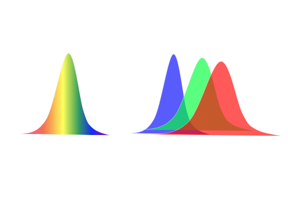
Chromatic dispersion affects all optical transmissions to some degree.These effects become more pronounced as the transmission rate increases and fiber length increases.
Factors contributing to increasing chromatic dispersion signal distortion include the following:
1. Laser spectral width, modulation method, and frequency chirp. Lasers with wider spectral widths and chirp have shorter dispersion limits. It is important to refer to manufacturer specifications to determine the total amount of dispersion that can be tolerated by the lightwave equipment.
2. The wavelength of the optical signal. Chromatic dispersion varies with wavelength in a fiber. In a standard non-dispersion shifted fiber (NDSF G.652), chromatic dispersion is near or at zero at 1310 nm. It increases positively with increasing wavelength and increases negatively for wavelengths less than 1310 nm.
3. The optical bit rate of the transmission laser. The higher the fiber bit rate, the greater the signal distortion effect.
4. The chromatic dispersion characteristics of fiber used in the link. Different types of fiber have different dispersion characteristics.
5. The total fiber link length, since the effect is cumulative along the length of the fiber.
6. Any other devices in the link that can change the link’s total chromatic dispersion including chromatic dispersion compensation modules.
7. Temperature changes of the fiber or fiber cable can cause small changes to chromatic dispersion. Refer to the manufacturer’s fiber cable specifications for values.
Methods to Combat Link Chromatic Dispersion
1. Change the equipment laser with a laser that has a specified longer dispersion limit. This is typically a laser with a more narrow spectral width or a laser that has some form of precompensation. As laser spectral width decreases, chromatic dispersion limit increases.
2. For new construction, deploy NZ-DSF instead of SSMF fiber.NZ-DSF has a lower chromatic dispersion specification.
3. Insert chromatic dispersion compensation modules (DCM) into the fiber link to compensate for the excessive dispersion. The optical loss of the DCM must be added to the link optical loss budget and optical amplifiers may be required to compensate.
4. Deploy a 3R optical repeater (re-amplify, reshape, and retime the signal) once a link reaches chromatic dispersion equipment limit.
5. For long haul undersea fiber deployment, splicing in alternating lengths of dispersion compensating fiber can be considered.
6. To reduce chromatic dispersion variance due to temperature, buried cable is preferred over exposed aerial cable.
Unlock Premium Content
Join over 400K+ optical network professionals worldwide. Access premium courses, advanced engineering tools, and exclusive industry insights.
Already have an account? Log in here


