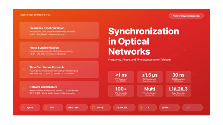
Recently I came across a non-optical background candidate who asked me what are OTU, OCH, ODU, etc in optical. So I came up with this diagram which helped him to understand in the simplest form and hope it will help many others too.
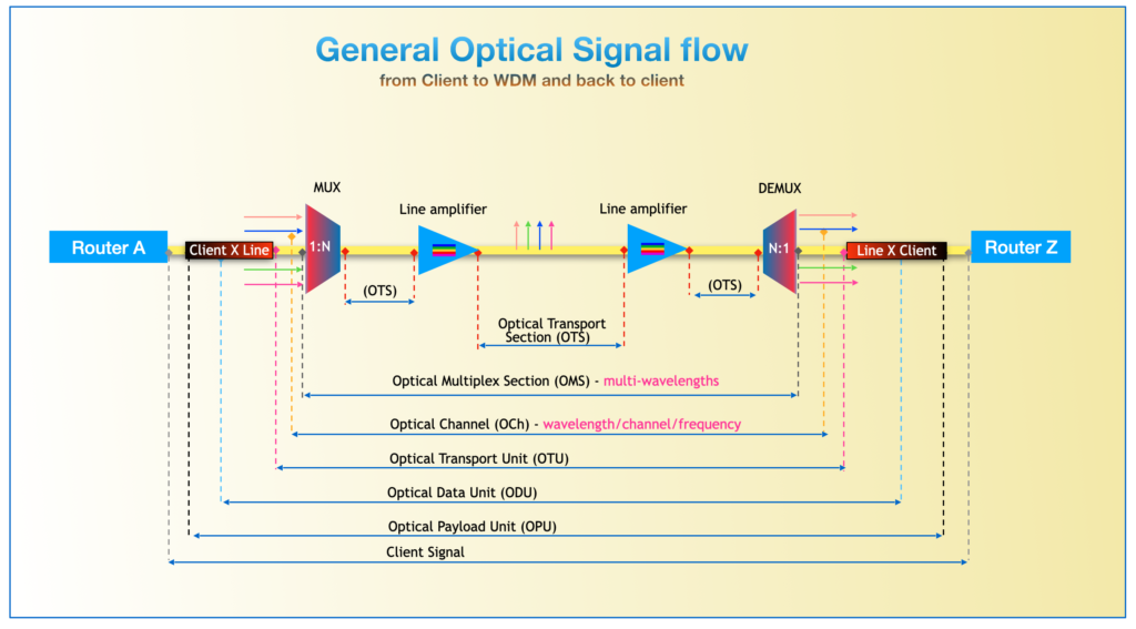
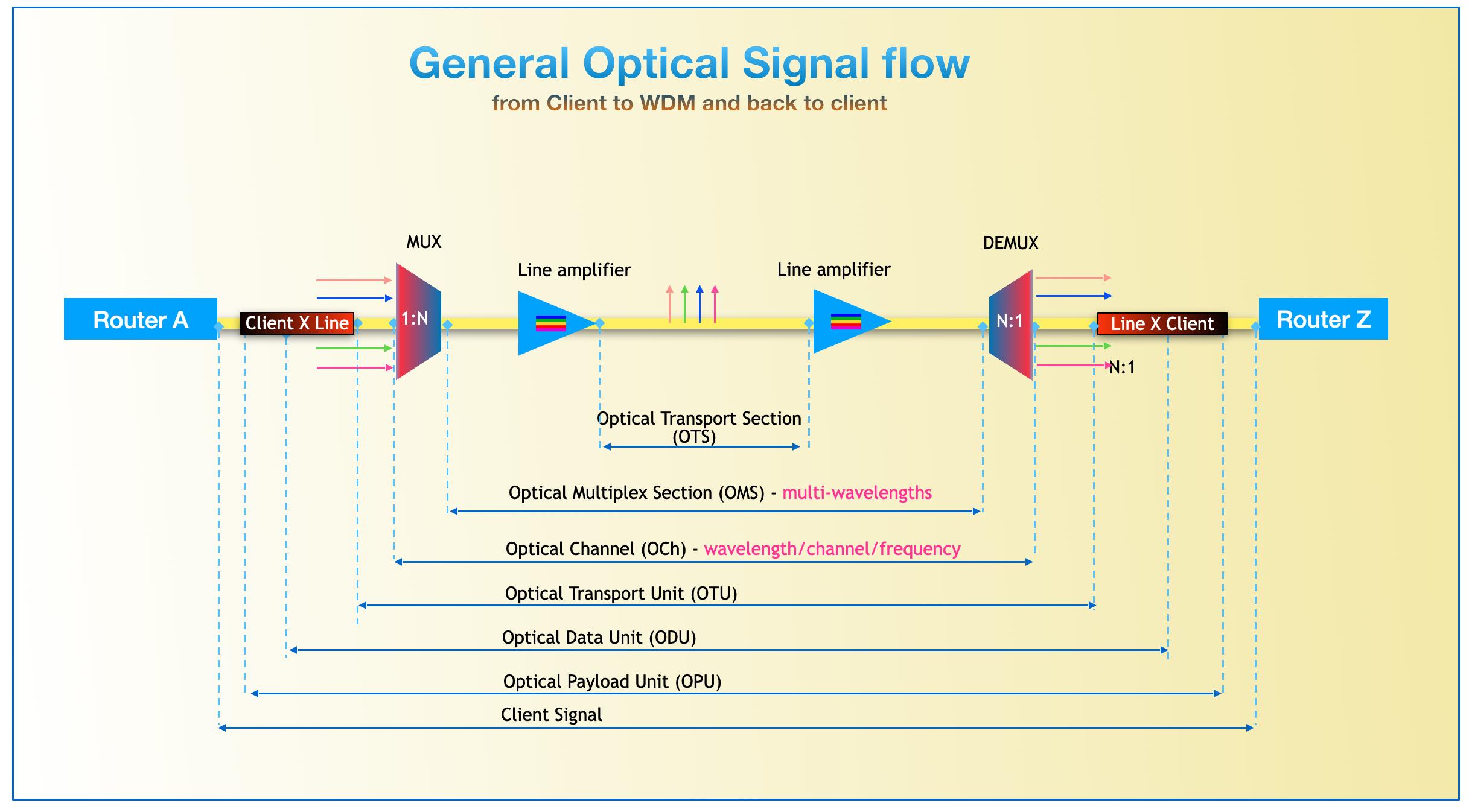
Complete optical signal flow from router to router through all OTN layers
The above image shows how a signal received from the router is sent over the Optical layer and then received back at another end. It consists of a few terminologies that are:
Client Signal
Client Signal is the actual payload that is to be carried over the optical layer and is generated from a router mostly and feed into client ports of an optical card called a transponder or muxponder. The client signal or actual payload to be transported could be of any existing protocol such as SONET/SDH, GFP, IP, and GbE.
Common Client Signal Types:
- Ethernet: 1GE, 10GE, 40GE, 100GE, 400GE - Most common in modern networks
- SONET/SDH: OC-3/STM-1 through OC-768/STM-256 - Legacy telecommunications
- Fibre Channel: 1G, 2G, 4G, 8G, 16G FC - Storage area networks
- IP Packets: Direct IP traffic without additional framing
- Other protocols: CPRI (for 5G fronthaul), Video (SDI/SMPTE), InfiniBand
Key Point: OTN is protocol-agnostic, meaning it can transparently transport any of these client types without modifying their native format, timing, or management information.
Optical Channel Payload Unit (OPU)
Client signal alongwith added overhead OH makes an OPU. OPU supports various types of clients and provides information on the type of signal transported over the next layer. The ITU-T G.709 currently supports asynchronous as well as synchronous mappings of client signals into the payload.
Key Functions of OPU:
- Payload Type Indication (PT): Identifies what type of client signal is carried (e.g., Ethernet, SDH, Fibre Channel)
- Mapping Information: Describes how the client signal is mapped into the OPU structure
- Synchronous Mapping: Used when the client rate exactly matches the OPU rate
- Asynchronous Mapping: Used when the client rate differs slightly from OPU rate, with justification bytes to accommodate the difference
- Generic Mapping Procedure (GMP): Modern, flexible method for mapping any constant bit-rate client into OPU
Technical Detail: The OPU overhead area is relatively small (typically 14-16 bytes per frame row), but it carries critical information that enables the receiver to correctly extract and reconstruct the original client signal. This overhead ensures that signals with slightly different clock rates can be accommodated without data loss.
Optical Channel Data Unit (ODU)
OPU alongwith overhead makes ODU. Added overhead allows users to support Path monitoring (PM), Tandem connection monitoring (TCM), and Automatic Protection Switching (APS).
Detailed ODU Overhead Functions:
- Path Monitoring (PM): End-to-end monitoring using BIP-8 (Bit Interleaved Parity) for error detection. Includes Trail Trace Identifier (TTI) for path verification, Backward Error Indication (BEI) reporting errors to the far end, and Backward Defect Indication (BDI) signaling path failures.
- Tandem Connection Monitoring (TCM): Up to 6 independent monitoring levels (TCM1 through TCM6) that enable nested monitoring. This is crucial when signals traverse multiple network operators' domains - each operator can have their own TCM level to monitor signal quality through their network segment without interfering with other operators' monitoring.
- Automatic Protection Switching (APS): Coordinates protection switching between working and protection paths. Enables sub-50ms recovery from network failures, meeting carrier-grade reliability requirements. APS bytes carry switching commands and status information.
- General Communication Channels (GCC1/GCC2): In-band management channels for communication between network elements at the ODU path level.
- Fault Type and Fault Location (FTFL): Carries detailed information about fault types and locations, enabling rapid troubleshooting and reducing mean time to repair (MTTR).
- Experimental Bytes (EXP): Reserved for vendor-specific features and future standardization.
ODU Hierarchy: Different ODU rates exist to accommodate various client speeds:
- ODU0: 1.25 Gbps (for 1 Gigabit Ethernet)
- ODU1: 2.5 Gbps (for OC-48/STM-16)
- ODU2: 10 Gbps (for 10 Gigabit Ethernet, OC-192/STM-64)
- ODU3: 40 Gbps (for 40 Gigabit Ethernet)
- ODU4: 100 Gbps (for 100 Gigabit Ethernet)
- ODUflex: Flexible rate container for non-standard rates
- ODUCn: Beyond-100G rates (n × 100G for 200G, 400G, 800G systems)
Optical Channel Transport Unit (OTU)
ODU with OH and FEC (Forward error correction) makes OTU. OTU is used in the OTN to support transport via one or more optical channel connections. FEC enables the correction and detection of errors in an optical link.
Forward Error Correction (FEC) - The Power of OTU:
FEC is one of the most significant advantages of OTN technology. It adds redundant bits to the transmitted data stream, allowing the receiver to detect and correct errors without requiring retransmission.
FEC Benefits:
- Extended Reach: Standard Reed-Solomon RS(255,239) FEC provides approximately 6.2 dB coding gain, which can extend transmission distance by up to 80% or enable skipping expensive amplifier sites
- Improved Signal Quality: Corrects errors caused by noise, attenuation, chromatic dispersion, PMD, and nonlinear effects
- Higher System Margin: Enables operation at lower OSNR (Optical Signal-to-Noise Ratio) values
- Cost Reduction: Reduces need for expensive optical components by improving tolerance to impairments
Modern FEC Types: Beyond standard FEC, modern systems use enhanced FEC schemes like SD-FEC (Soft-Decision FEC) and advanced concatenated codes that can provide 10+ dB coding gain for long-haul submarine and ultra-long-haul terrestrial systems.
OTU Frame Structure Components:
- Frame Alignment Signal (FAS): Fixed pattern (0xF6F628 in hexadecimal) used for frame synchronization. The receiver searches for this pattern to align with frame boundaries.
- Multi-Frame Alignment Signal (MFAS): Counter from 0-255 that enables multi-frame alignment. Some overhead bytes are only accessed in specific multi-frames.
- Section Monitoring (SM): Includes BIP-8 for error monitoring, Trail Trace Identifier (TTI) for OTU section verification, Backward Error Indication (BEI) and Backward Defect Indication (BDI) for alarm propagation.
- General Communication Channel 0 (GCC0): Management communication channel at the OTU section level, used for network management communication between adjacent network elements.
- FEC Bytes: The OTU frame concludes with FEC bytes (256 bytes for standard FEC) that enable error correction at the receiver.
OTU Rate Hierarchy: Similar to ODU, different OTU rates exist: OTU1 (2.67 Gbps), OTU2 (10.71 Gbps), OTU3 (43.02 Gbps), OTU4 (111.81 Gbps), and flexible OTUCn (n×100G). The OTU rate is slightly higher than the corresponding ODU rate to accommodate the FEC overhead.
Optical Channel (OCH)
OTU with FEC another overhead makes OCH. OCH is generally a frequency/wavelength/color that will be sent to a MUX multiplexer where different channels with be multiplexed to be carried over a single strand of optical fiber.
Understanding Wavelength Division Multiplexing:
The OCH layer is where the electrical OTU signal is converted to an optical signal at a specific wavelength (color of light). This enables Dense Wavelength Division Multiplexing (DWDM), a technology that dramatically increases fiber capacity.
DWDM Fundamentals:
- ITU-T Frequency Grid: Standard wavelengths are defined on a grid with 50 GHz or 100 GHz spacing in the C-band (1530-1565 nm)
- Wavelength Identification: Each channel is identified by its center wavelength (e.g., 1550.12 nm) or frequency (e.g., 193.4 THz)
- Channel Capacity: A typical 96-channel DWDM system with 100G per channel provides 9.6 Tbps capacity on a single fiber
- Flexible Grid: Modern systems support flexible grid spacing (12.5 GHz, 6.25 GHz) for optimal spectrum utilization
Modern Coherent Modulation:
Modern OCH implementations use sophisticated coherent modulation formats:
- DP-QPSK: Dual-Polarization Quadrature Phase Shift Keying - Used for 100G systems, providing good reach (2000+ km)
- DP-16QAM: 16-state Quadrature Amplitude Modulation - Used for 200G systems, balancing reach and capacity
- DP-64QAM: 64-state modulation - Used for 400G+ in metro applications where reach is <500 km
- Probabilistic Constellation Shaping (PCS): Advanced technique that optimizes the signal constellation shape to maximize capacity while maintaining reach
Technical Insight: The transponder's laser and modulator convert the electrical OTU signal into modulated light. The laser is precisely tunable to any ITU-T grid wavelength, enabling flexible wavelength assignment. Modern coherent transponders include sophisticated DSP (Digital Signal Processing) that performs pre-distortion, chromatic dispersion pre-compensation, and adaptive equalization.
Optical Channel Multiplexing Section (OMS)
Once the optical channel is created, additional non-associated overhead is added to each OCh frequency and thus OMS is formed. This is the output of mixed signals called composite signal on MUX, multiplexer. This is between MUX to DEMUX.
OMS Layer Functions in Detail:
- Wavelength Multiplexing: The MUX (multiplexer) combines multiple OCH signals at different wavelengths onto a single fiber. This can be done using passive optical components (thin film filters, array waveguide gratings) or active components (wavelength selective switches).
- Composite Signal Management: The OMS manages the aggregate multi-wavelength signal. All wavelengths travel together through the fiber, but maintain their individual identity due to their different optical frequencies.
- Power Management: OMS monitors and controls both the aggregate optical power and individual channel powers. Maintaining proper power levels is critical for optimal system performance and avoiding nonlinear effects.
- OADM Operations: Optical Add-Drop Multiplexers (OADMs) can add or drop specific wavelengths at intermediate nodes without demultiplexing all channels. This enables efficient wavelength routing in mesh networks.
- ROADM Architecture: Reconfigurable OADMs (ROADMs) use wavelength selective switches to dynamically add, drop, or route wavelengths. Modern ROADM architectures are "Colorless, Directionless, Contentionless" (CDC), meaning any wavelength can be added/dropped from any port in any direction without blocking.
OMS Section Boundaries: An OMS section extends from a multiplexer to a demultiplexer, potentially passing through multiple intermediate OADMs/ROADMs. Each time wavelengths are added, dropped, or routed, the system is operating at the OMS layer. The OMS overhead (though not fully standardized) carries information about the multiplexed signal for maintenance and operational purposes.
Wavelength Selective Switch (WSS) Technology:
Modern OMS systems rely heavily on WSS technology:
- Software Defined: Wavelengths can be routed by software control, enabling network automation
- Per-Channel Power Control: Each wavelength's power can be independently adjusted
- Flexible Grid Support: Can handle both fixed grid and flexible grid wavelength assignments
- Fast Switching: Sub-second wavelength path reconfiguration enables rapid service provisioning
Optical Transmission Section (OTS)
The optical transmission section (OTS) layer transports the OTS payload as well as the OTS overhead (OTS-OH). The OTS OH, although not fully defined, is used for maintenance and operational functions. The OTS layer allows the network operator to perform monitoring and maintenance tasks between the Optical Network elements, which include: OADMs, multiplexers, de-multiplexers, and optical switches.
Physical Layer Management:
The OTS layer is where physics really matters. It manages the actual propagation of light through optical fiber and all associated impairments.
OTS Section Definition: An OTS section extends from one optical amplifier (or network element with amplifier functionality) to the next. Typical spans range from 40-120 km depending on fiber type, signal parameters, and system design.
Optical Impairments Managed by OTS:
- Fiber Attenuation: Standard Single-Mode Fiber (SMF) has loss of approximately 0.2 dB/km at 1550 nm. An 80 km span loses about 16 dB of signal power, which must be compensated by amplifiers.
- Chromatic Dispersion (CD): Different wavelengths travel at slightly different speeds through fiber, causing pulse broadening. Standard SMF has CD of about 17 ps/(nm·km) at 1550 nm. Managed through:
- Dispersion Compensating Fiber (DCF) modules
- Fiber Bragg Gratings (FBG)
- Electronic Dispersion Compensation (EDC) in receivers
- Digital Signal Processing (DSP) in coherent systems
- Polarization Mode Dispersion (PMD): Fiber birefringence causes pulse distortion. Modern systems use adaptive PMD compensation in coherent receivers.
- Optical Signal-to-Noise Ratio (OSNR): Each amplifier adds noise (ASE - Amplified Spontaneous Emission). OSNR degrades through amplifier chains. Typical requirement: >15 dB OSNR for 100G systems, >20 dB for 400G systems.
- Nonlinear Effects: High optical power causes nonlinear interactions in fiber:
- Self-Phase Modulation (SPM): Signal modulates its own phase
- Cross-Phase Modulation (XPM): One wavelength modulates another's phase
- Four-Wave Mixing (FWM): Three wavelengths generate a fourth
- Stimulated Raman Scattering (SRS): Power transfer between wavelengths
Optical Amplification Technology:
Erbium-Doped Fiber Amplifiers (EDFAs): The workhorse of modern optical networks
- Gain: Typically 15-25 dB, amplifying the entire C-band simultaneously
- Noise Figure: 4-6 dB, adding ASE noise to the signal
- Pump Lasers: 980 nm or 1480 nm lasers pump the erbium ions to excited states
- Gain Flattening: Gain equalizing filters ensure flat gain across all wavelengths
- Dynamic Gain Equalization (DGE): Modern amplifiers actively adjust per-channel gain
Alternative Amplification: Raman amplifiers pump the transmission fiber itself, providing distributed amplification with lower noise. Semiconductor Optical Amplifiers (SOAs) are used in some applications but have limitations compared to EDFAs.
Link Budget and System Design:
OTS design requires careful link budget calculation:
- Transmitted Power: Typically 0 to +5 dBm per channel
- Fiber Loss: 0.2 dB/km × span length
- Connector/Splice Loss: 0.5-1 dB per connection
- Component Loss: MUX/DEMUX, WSS, OADM insertions
- Margin: 3-6 dB safety margin for aging and repairs
- Required OSNR: Depends on modulation format and data rate
- Receiver Sensitivity: Typically -20 to -10 dBm
How the Layers Work Together: End-to-End Signal Journey
Understanding how all these layers interact is crucial to grasping the complete picture of optical signal flow:
Transmit Direction (Router A to Router Z):
- Client Signal Generation: Router A generates a client signal (e.g., 100 Gigabit Ethernet frames)
- OPU Encapsulation: Transponder maps the client signal into OPU, adding payload type and mapping information
- ODU Addition: ODU overhead is added, enabling end-to-end path monitoring, TCM through transit networks, and protection switching capabilities
- OTU Formation: OTU overhead and powerful FEC are added, preparing the signal for optical transmission with extended reach
- OCH Conversion: The electrical OTU signal is converted to light at a specific wavelength (e.g., 1550.12 nm, ITU-T Channel 34)
- OMS Multiplexing: The MUX combines this OCH with dozens of other wavelengths into a multi-wavelength composite signal
- OTS Transmission: The composite signal travels through fiber spans with periodic amplification, battling attenuation, dispersion, and noise
Receive Direction (Router Z receives from Router A):
- OTS Reception: The multi-wavelength signal is received after traveling through potentially thousands of kilometers
- OMS Demultiplexing: The DEMUX separates the composite signal back into individual wavelengths
- OCH to OTU: The optical signal at the target wavelength is converted back to electrical OTU signal by the receiver transponder
- FEC Decoding: The receiver uses FEC to detect and correct transmission errors, dramatically improving signal quality
- ODU Processing: ODU overhead is processed to extract monitoring information, verify path integrity, and coordinate any protection switching if needed
- OPU Demapping: The client signal is extracted from the OPU using the mapping information
- Client Delivery: The original client signal (100GE frames) is delivered to Router Z, completing the journey
Transparency Achieved: Throughout this entire journey, the client signal remains completely transparent. Router A and Router Z communicate as if directly connected, unaware of the complex OTN infrastructure between them. This transparency, combined with powerful monitoring, protection, and error correction, is what makes OTN the gold standard for carrier networks worldwide.
Latest Industry Developments
The optical networking industry continues to evolve rapidly with several key trends:
Beyond-100G Evolution:
- 400G Mainstream: 400G systems are now deployed widely for metro and data center interconnect
- 800G Commercial Deployment: 800G long-haul systems entered commercial deployment in 2024-2025
- 1.6T on the Horizon: 1.6 Tbps per wavelength systems are in advanced trials
- OTUCn Flexibility: The flexible OTUCn container (n×100G) enables any multiple of 100G
Fine-Grained OTN (fgOTN):
The ITU-T G.709.25 standard for OSU (Optical Service Unit) entered large-scale commercial deployment in 2025:
- Supports flexible service access from 2 Mbps to 100 Gbps
- Microsecond-level latency commitments for financial services
- Strict isolation for government and enterprise applications
- Enables cloud-network convergence and edge computing interconnectivity
AI and Automation:
- Predictive Maintenance: AI/ML algorithms predict component failures before they impact service
- Automated Optimization: Systems self-optimize for capacity, reach, and power consumption
- Anomaly Detection: ML models detect unusual patterns indicating potential issues
- Capacity Planning: AI-driven forecasting improves network investment decisions
Software-Defined Optical Networks:
- Integration with SDN controllers enables programmable optical infrastructure
- Automated service provisioning reduces deployment time from weeks to minutes
- Multi-layer optimization across IP and optical layers
- Essential for 5G transport and cloud interconnect applications
For more details, please refer to the official ITU-T standards and below helpful links:
MapYourTech OTN Standards & ITU-T Standard Explorer
MapYourTech SDH/SONET/PDH Infographics
MapYourTech Optical Impairments Infographics
MapYourTech Optical Fibers Infographics
ITU-T G.709: Interfaces for the optical transport network (OTN)
Unlock Premium Content
Join over 400K+ optical network professionals worldwide. Access premium courses, advanced engineering tools, and exclusive industry insights.
Already have an account? Log in here