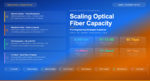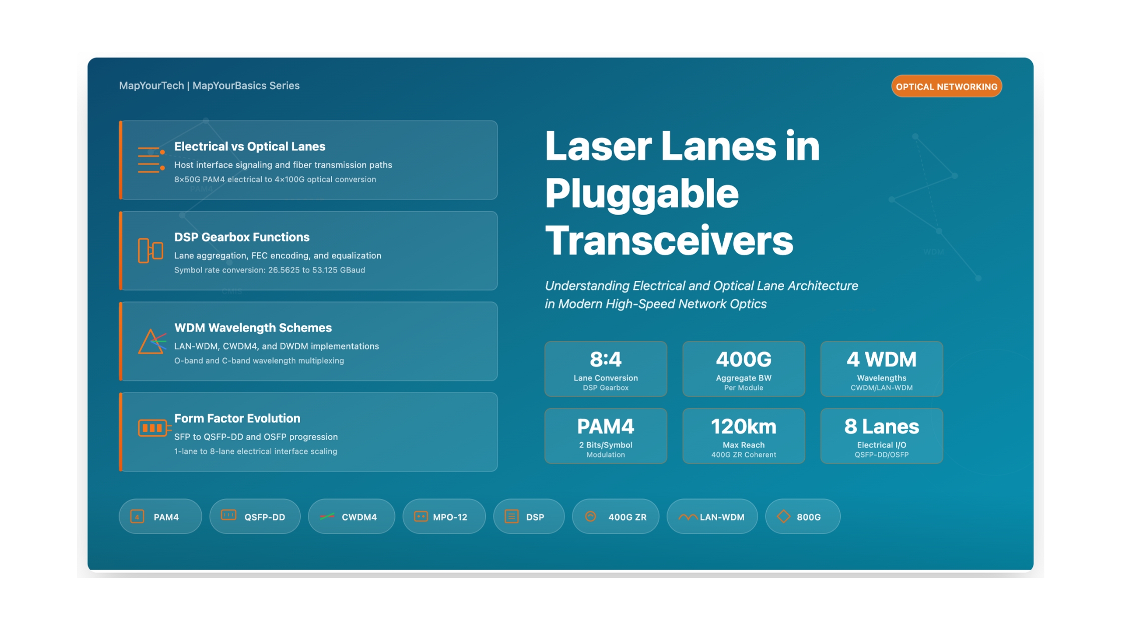
Laser Lanes in Pluggable Optical Transceivers
Understanding Electrical and Optical Lane Architecture in Modern High-Speed Network Optics
1. Introduction
The concept of "lanes" in pluggable optical transceivers represents one of the most fundamental architectural elements that determine how data moves between network equipment and optical fiber infrastructure. As data rates have evolved from 10G to 400G and beyond, the lane architecture has become increasingly sophisticated, involving complex relationships between electrical interfaces, signal processing, and optical transmission paths.
This article provides a comprehensive examination of laser lanes in pluggable optics, covering electrical and optical lane definitions, the role of Digital Signal Processors (DSP) in lane conversion, wavelength division multiplexing schemes, and practical considerations for different transceiver types used in modern data center and telecommunications networks.
2. Fundamental Concepts: Electrical vs. Optical Lanes
Understanding the distinction between electrical lanes and optical lanes is essential for grasping how modern pluggable transceivers function. These two types of lanes serve different purposes in the data transmission chain and do not always maintain a one-to-one relationship.
Continue Reading This Article
Sign in with a free account to unlock the full article and access the complete MapYourTech knowledge base.
2.1 Electrical Lanes (Host Interface)
Electrical lanes represent the high-speed serial data paths between the host system (switch, router, or network interface card) and the pluggable transceiver module. The host Application-Specific Integrated Circuit (ASIC) communicates with the transceiver through these electrical lanes, which are defined by industry-standard electrical interface specifications.
Definition: Electrical Lane
An electrical lane is a single high-speed serialized differential signal pair carrying data between the host board and the transceiver module. The number of electrical lanes and their signaling rate determine the aggregate bandwidth capacity at the host interface.
| Interface Standard | Lanes | Rate per Lane | Modulation | Aggregate BW |
|---|---|---|---|---|
| XLAUI (40G) | 4 | 10.3125 Gb/s | NRZ | 40 Gb/s |
| CAUI-4 (100G) | 4 | 25.78125 Gb/s | NRZ | 100 Gb/s |
| 400GAUI-8 | 8 | 53.125 Gb/s | PAM4 | 400 Gb/s |
| 800GAUI-8 | 8 | 106.25 Gb/s | PAM4 | 800 Gb/s |
2.2 Optical Lanes (Line Interface)
Optical lanes represent the individual optical channels used to transmit data across the fiber optic medium. An optical lane can be implemented using either a separate physical fiber strand (parallel optics) or a distinct wavelength on a shared fiber (wavelength division multiplexing). Each optical lane has its own laser transmitter and photodetector receiver pair.
Definition: Optical Lane
An optical lane is a single optical channel capable of carrying serialized data, implemented either as a dedicated fiber in a parallel ribbon or as a specific wavelength in a WDM system.
3. DSP Gearbox: Bridging Electrical and Optical Domains
The Digital Signal Processor (DSP) within modern pluggable transceivers serves multiple critical functions, with one of the most important being the "gearbox" function that converts between different lane counts and signaling rates on the electrical and optical sides.
Lane Conversion Relationship
Aggregate Bandwidth = Nelectrical × Rateelectrical = Noptical × Rateoptical

Example: 400G DR4 Transceiver
Electrical: 8 lanes × 50 Gb/s (PAM4) = 400 Gb/s
Optical:    4 lanes × 100 Gb/s (PAM4) = 400 Gb/s
3.1 Modulation Format Conversion
Beyond simple lane count conversion, the DSP often performs modulation format conversion between the electrical and optical domains. Non-Return-to-Zero (NRZ) and Pulse Amplitude Modulation 4-level (PAM4) are the two primary modulation formats used in current pluggable transceivers.
4. Optical Lane Architectures
Pluggable transceivers employ various optical lane architectures depending on the target application, distance requirements, and cost considerations. The three primary approaches are parallel single-wavelength optics, wavelength division multiplexing (WDM), and bi-directional (BiDi) transmission.
4.1 Wavelength Division Multiplexing Schemes
WDM architectures multiplex multiple wavelengths onto a single fiber pair. Three primary WDM schemes are used in pluggable transceivers:
| Scheme | Wavelength Range | Channel Spacing | Laser Type | Applications |
|---|---|---|---|---|
| LAN-WDM | 1295-1310nm (O-band) | ~4.5nm | Cooled DFB/EML | 100G LR4, 400G LR8 |
| CWDM4 | 1271-1331nm (O-band) | 20nm | Uncooled DML | 100G CWDM4, 400G FR4/LR4 |
| DWDM | 1530-1565nm (C-band) | 100GHz/50GHz | Tunable, Coherent | 400G ZR/ZR+ |
5. Form Factors and Lane Support
Different transceiver form factors support varying numbers of electrical lanes based on their physical connector specifications and the generation of electrical interface they implement.
| Form Factor | Elec. Lanes | Lane Rate | Modulation | Total Bandwidth |
|---|---|---|---|---|
| SFP28 | 1 | 25 Gb/s | NRZ | 25 Gb/s |
| QSFP28 | 4 | 25 Gb/s | NRZ | 100 Gb/s |
| QSFP56 | 4 | 50 Gb/s | PAM4 | 200 Gb/s |
| QSFP-DD | 8 | 50 Gb/s | PAM4 | 400 Gb/s |
| QSFP-DD800 | 8 | 100 Gb/s | PAM4 | 800 Gb/s |
| OSFP | 8 | 50-100 Gb/s | PAM4 | 400-800 Gb/s |
6. Comprehensive Lane Configuration Matrix
The following table details the electrical-to-optical lane mapping for major transceiver types used in data center and telecommunications networks.
| Module Type | Elec. Lanes | Opt. Lanes | Wavelength Scheme | Connector | Reach |
|---|---|---|---|---|---|
| 40G SR4 | 4 × 10G NRZ | 4 × 10G | 4 × 850nm Parallel | MPO-12 | 100-150m |
| 100G SR4 | 4 × 25G NRZ | 4 × 25G | 4 × 850nm Parallel | MPO-12 | 100m |
| 100G LR4 | 4 × 25G NRZ | 4 × 25G | LAN-WDM (1295-1310nm) | LC Duplex | 10km |
| 100G CWDM4 | 4 × 25G NRZ | 4 × 25G | CWDM (1271-1331nm) | LC Duplex | 2km |
| 400G SR8 | 8 × 50G PAM4 | 8 × 50G | 8 × 850nm Parallel | MPO-16 | 70-100m |
| 400G DR4 | 8 × 50G PAM4 | 4 × 100G | 4 × 1310nm Parallel | MPO-12 | 500m |
| 400G FR4 | 8 × 50G PAM4 | 4 × 100G | CWDM (1271-1331nm) | LC Duplex | 2km |
| 400G LR4 | 8 × 50G PAM4 | 4 × 100G | CWDM (1271-1331nm) | LC Duplex | 10km |
| 400G ZR | 8 × 50G PAM4 | 1 × 400G | DWDM C-band (Coherent) | LC Duplex | 80-120km |
| 800G DR8 | 8 × 100G PAM4 | 8 × 100G | 8 × 1310nm Parallel | MPO-16 | 500m |
7. MPO Connector Fiber Mapping
Multi-fiber Push On (MPO) connectors are used extensively in parallel optical systems. Understanding the fiber-to-lane mapping is critical for proper cable installation and troubleshooting.
MPO-12 Fiber Assignment (400G DR4)
Fibers 1-4: Receive lanes 0-3
Fibers 5-8: Unused (in 4-lane configuration)
Fibers 9-12: Transmit lanes 3-0 (reversed order)
8. Breakout Applications
Parallel optical transceivers enable "breakout" configurations where a single high-speed port can be split into multiple lower-speed connections. Common breakout scenarios include:
| Source Module | Breakout Configuration | Cable Type | Use Case |
|---|---|---|---|
| 400G DR4 | 4 × 100G DR | MPO-12 to 4×LC | Leaf-Spine connectivity |
| 100G SR4 | 4 × 25G SR | MPO-12 to 4×LC | Server connectivity |
| 400G SR8 | 2 × 200G SR4 | MPO-16 to 2×MPO-12 | ToR aggregation |
| 40G SR4 | 4 × 10G SR | MPO-12 to 4×LC | Legacy migration |
9. Future Trends
The evolution of lane architecture continues as the industry moves toward 800G and 1.6T solutions:
| Generation | Electrical Interface | Optical Implementation | Target Application |
|---|---|---|---|
| 800G | 8 × 100G PAM4 | 8 × 100G PSM or 4 × 200G WDM | Data center spine |
| 1.6T | 16 × 100G PAM4 | 8 × 200G or coherent | Hyperscale interconnect |
| Next-Gen | 8 × 200G PAM4 | Advanced coherent/IM-DD hybrid | Cloud-scale networks |
10. Conclusion
The concept of laser lanes in pluggable optical transceivers encompasses a sophisticated interplay between electrical host interfaces, digital signal processing, and optical transmission technologies. As network bandwidth demands continue to grow, the lane architecture has evolved from simple one-to-one electrical-to-optical mappings toward complex DSP-based gearbox systems that convert between different lane counts, signaling rates, and modulation formats.
Understanding these lane architectures is essential for network engineers and architects involved in system design, deployment, and troubleshooting. Key considerations include selecting appropriate optical lane configurations based on fiber infrastructure and distance requirements, understanding the gearbox functionality within transceivers that bridge electrical and optical domains, properly mapping fiber assignments for multi-lane parallel optics, and using breakout capabilities for efficient port utilization.
As the industry moves toward 800G and 1.6T solutions, the fundamental principles of lane-based architecture will remain relevant while the specific implementations continue to advance in speed and efficiency.
References
- IEEE 802.3ba – 40Gb/s and 100Gb/s Ethernet
- IEEE 802.3bs – 200Gb/s and 400Gb/s Ethernet
- IEEE 802.3cd – 50Gb/s, 100Gb/s, and 200Gb/s Ethernet
- OIF CEI-56G-VSR – 56G Very Short Reach Interface
- QSFP-DD MSA – Hardware Specification
- CMIS – Common Management Interface Specification Rev 5.0
- 100G Lambda MSA – Technical Specifications
- Sanjay Yadav, "Optical Network Communications: An Engineer's Perspective" – Bridge the Gap Between Theory and Practice in Optical Networking
Developed by MapYourTech Team
For educational purposes in Optical Networking Communications Technologies
Note: This guide is based on industry standards, best practices, and real-world implementation experiences. Specific implementations may vary based on equipment vendors, network topology, and regulatory requirements. Always consult with qualified network engineers and follow vendor documentation for actual deployments.
Feedback Welcome: If you have any suggestions, corrections, or improvements to propose, please feel free to write to us at [email protected]

Optical Networking Engineer & Architect • Founder, MapYourTech
Optical networking engineer with nearly two decades of experience across DWDM, OTN, coherent optics, submarine systems, and cloud infrastructure. Founder of MapYourTech. Read full bio →
Follow on LinkedInRelated Articles on MapYourTech