Animated CTA Banner
MapYourTech
MapYourTech has always been about YOUR tech journey, YOUR questions, YOUR thoughts, and most importantly, YOUR growth. It’s a space where we "Map YOUR Tech" experiences and empower YOUR ambitions.
To further enhance YOUR experience, we are working on delivering a professional, fully customized platform tailored to YOUR needs and expectations.
Thank you for the love and support over the years. It has always motivated us to write more, share practical industry insights, and bring content that empowers and inspires YOU to excel in YOUR career.
We truly believe in our tagline:
“Share, explore, and inspire with the tech inside YOU!”
Let us know what YOU would like to see next! Share YOUR thoughts and help us deliver content that matters most to YOU.
Share YOUR Feedback
Tag

Signal degradation

Browsing

While single-mode fibers have been the mainstay for long-haul telecommunications, multimode fibers hold their own, especially in applications where short distance and high bandwidth are critical. Unlike their single-mode counterparts, multimode fibers are not restricted by cut-off wavelength considerations, offering unique advantages.

The Nature of Multimode Fibers

Multimode fibers, characterized by a larger core diameter compared to single-mode fibers, allow multiple light modes to propagate simultaneously. This results in modal dispersion, which can limit the distance over which the fiber can operate without significant signal degradation. However, multimode fibers exhibit greater tolerance to bending effects and typically showcase higher attenuation coefficients.

Wavelength Windows for Multimode Applications

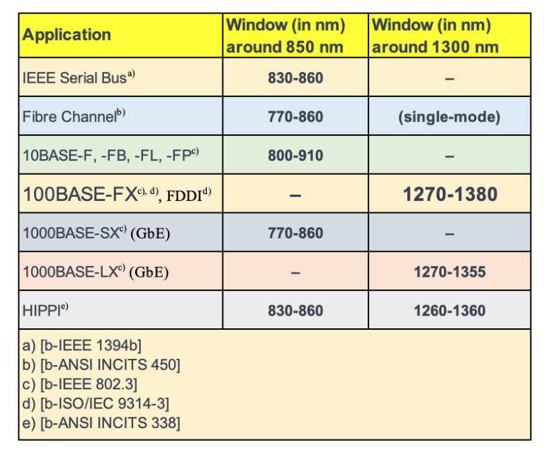
Multimode fibers shine in certain “windows,” or wavelength ranges, which are optimized for specific applications and classifications. These windows are where the fiber performs best in terms of attenuation and bandwidth.

#multimodeband

IEEE Serial Bus (around 850 nm): Typically used in consumer electronics, the 830-860 nm window is optimal for IEEE 1394 (FireWire) connections, offering high-speed data transfer over relatively short distances.

Fiber Channel (around 770-860 nm): For high-speed data transfer networks, such as those used in storage area networks (SANs), the 770-860 nm window is often used, although it’s worth noting that some applications may use single-mode fibers.

Ethernet Variants:

  • 10BASE (800-910 nm): These standards define Ethernet implementations for local area networks, with 10BASE-F, -FB, -FL, and -FP operating within the 800-910 nm range.
  • 100BASE-FX (1270-1380 nm) and FDDI (Fiber Distributed Data Interface): Designed for local area networks, they utilize a wavelength window around 1300 nm, where multimode fibers offer reliable performance for data transmission.
  • 1000BASE-SX (770-860 nm) for Gigabit Ethernet (GbE): Optimized for high-speed Ethernet over multimode fiber, this application takes advantage of the lower window around 850 nm.
  • 1000BASE-LX (1270-1355 nm) for GbE: This standard extends the use of multimode fibers into the 1300 nm window for Gigabit Ethernet applications.

HIPPI (High-Performance Parallel Interface): This high-speed computer bus architecture utilizes both the 850 nm and the 1300 nm windows, spanning from 830-860 nm and 1260-1360 nm, respectively, to support fast data transfers over multimode fibers.

Future Classifications and Studies

The classification of multimode fibers is a subject of ongoing research. Proposals suggest the use of the region from 770 nm to 910 nm, which could open up new avenues for multimode fiber applications. As technology progresses, these classifications will continue to evolve, reflecting the dynamic nature of fiber optic communications.

Wrapping Up: The Place of Multimode Fibers in Networking

Multimode fibers are a vital part of the networking world, particularly in scenarios that require high data rates over shorter distances. Their resilience to bending and capacity for high bandwidth make them an attractive choice for a variety of applications, from high-speed data transfer in industrial settings to backbone cabling in data centers.

As we continue to study and refine the classifications of multimode fibers, their role in the future of networking is guaranteed to expand, bringing new possibilities to the realm of optical communications.

References

https://www.itu.int/rec/T-REC-G/e

Non-linear interactions between the signal and the silica fibre transmission medium begin to appear as optical signal powers are increased to achieve longer span lengths at high bit rates. Consequently, non-linear fibre behaviour has emerged as an important consideration both in high capacity systems and in long unregenerated routes. These non-linearities can be generally categorized as either scattering effects (stimulated Brillouin scattering and stimulated Raman scattering) or effects related to the fibre’s intensity dependent index of refraction (self-phase modulation, cross-phase modulation, modulation instability, soliton formation and four-wave mixing). A variety of parameters influence the severity of these non-linear effects, including line code (modulation format), transmission rate, fibre dispersion characteristics, the effective area and non-linear refractive index of the fibre, the number and spacing of channels in multiple channel systems, overall unregenerated system length, as well as signal intensity and source line-width. Since the implementation of transmission systems with higher bit rates than 10 Gbit/s and alternative line codes (modulation formats) than NRZ-ASK or RZ-ASK, described in [b-ITU-T G-Sup.39], non‑linear fibre effects previously not considered can have a significant influence, e.g., intra‑channel cross-phase modulation (IXPM), intra-channel four-wave mixing (IFWM) and non‑linear phase noise (NPN).