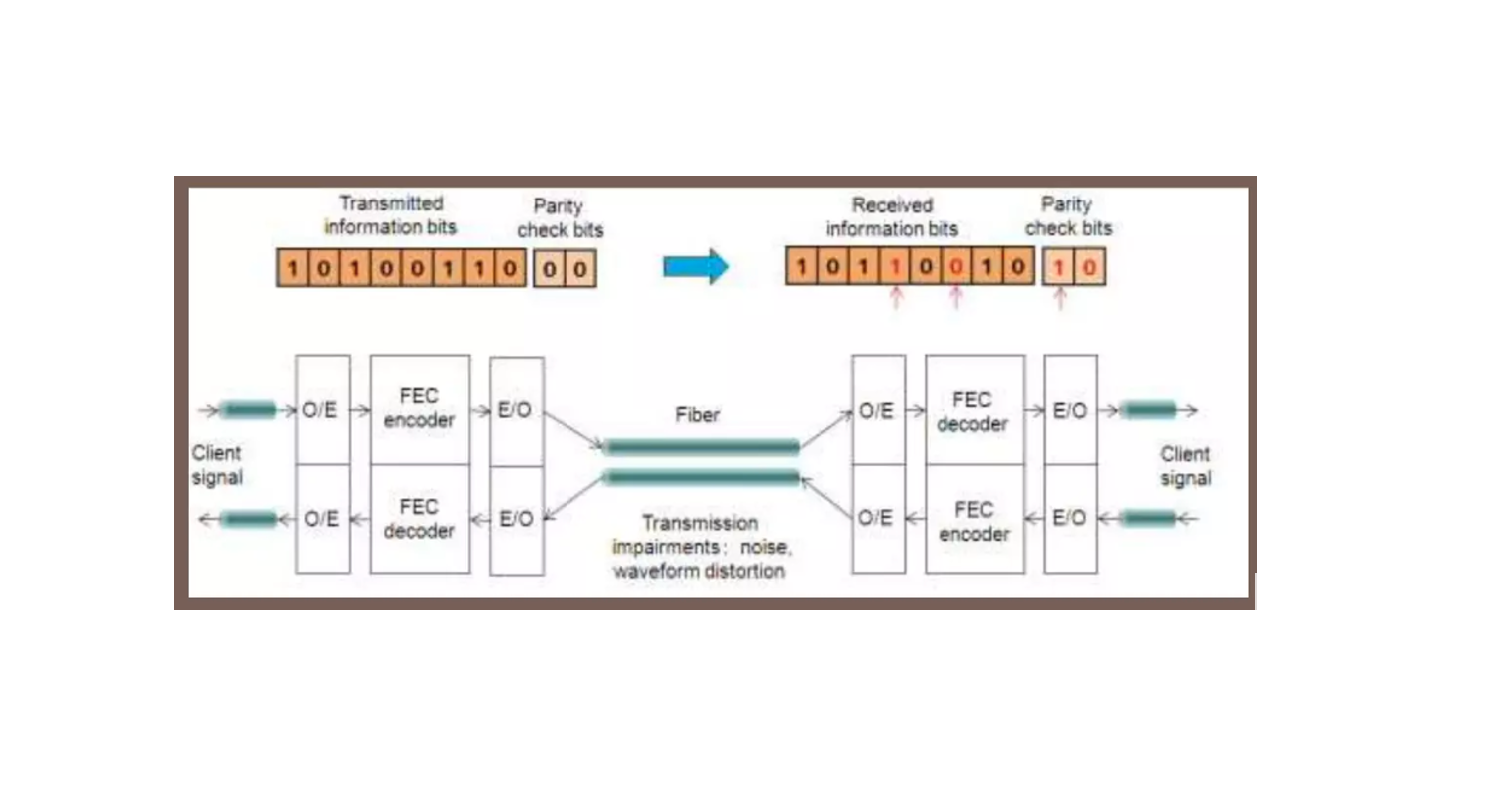
As we know that to improve correction capability, more powerful and complex FEC codes must be used. However, the more complex the FEC codes are, the more time FEC decoding will take. This term “baud” originates from the French engineer Emile Baudot, who was the inventor of 5-bit teletype code. The Baud rate actually refers to the number of signal or symbol changes that occurs per second. A symbol is one of the several voltage, frequency, or phase changes.
Baudrate = bitrate/number of bits per symbol ;
signal bandwidth = baud rate;
Baud rate:
It is the rate symbols which are generated at the source and, to a first approximation, equals to the electronic bandwidth of the transmission system. The baud rate is an important technology-dependent system performance parameter. This parameter defines the optical bandwidth of the transceiver, and it specifies the minimum slot width required for the corresponding flow(s).
Baud rate/symbol rate/transmission rate for a physical layer protocol is the maximum possible number of times a signal can change its state from a logical 1 to logical 0 or or vice-versa per second. These states are usually voltage, frequency, optical intensity or phase. This can also be described as the number of symbols that can be transmitted in 1 second. The relationship between baud rate and bitrate is given as.
Bit rate = baud rate * number of bits / baud
The number of bits per baud is deduced from the existing modulation scheme. Here, we are assuming that the number of bits per baud is one, so, the baud rate is the exactly same as the bit rate.
The spectral-width of the wavelength in GHz is equal to the symbol rate in Gbaud measured at the 3 dB point or the point where the power is half of the peak. As the baud rate increases, the spectral-width of the channels will increases proportionally. The higher baud rates, therefore, are unable to increase spectral efficiency, though there can be exceptions to this rule where a higher baud rate better aligns with the available spectrum. Increasing wavelength capacity with the baud rate, has far less impact on reach than increasing it with higher-order modulation.
Higher baud rates, offer the best potential for reducing the cost per bit in Flexi-grid DWDM networks and also in point-to-point fixed grid networks, even though higher baud rates are not significant in 50 GHz fixed grid ROADM networks. Higher baud rates also requires all the components of the optical interface, including the DSP, photodetector and A/D converters and modulators, to support the higher bandwidth. This places a limit on the maximum baud rate that is achievable with a given set of technology and may increase the cost of the interfaces if more expensive components are required.
Unlock Premium Content
Join over 400K+ optical network professionals worldwide. Access premium courses, advanced engineering tools, and exclusive industry insights.
Already have an account? Log in here


