
INTRODUCTION
For more than 30 years, Ethernet has evolved to meet the growing demands of packet‐switched networks. It has become the unifying technology enabling communications via the Internet and other networks using Internet Protocol (IP). Due to its proven low cost, known reliability, and simplicity, the majority of today’s internet traffic starts or ends on an Ethernet connection. This popularity has resulted in a complex ecosystem between carrier networks, enterprise networks, and consumers creating a symbiotic relationship between its various parts.In 2006, the IEEE 802.3 working group formed the Higher Speed Study Group (HSSG) and found that the Ethernet ecosystem needed something faster than 10 Gigabit Ethernet. The growth in bandwidth for network aggregation applications was found to be outpacing the capabilities of networks employing link aggregation with 10 Gigabit Ethernet. As the HSSG studied the issue, it was determined that computing and network aggregation applications were growing at different rates. For the first time in the history of Ethernet, a Higher Speed Study Group determined that two new rates were needed: 40 gigabit per second for server and computing applications and 100 gigabit per second for network aggregation applications.The IEEE P802.3ba 40 Gb/s and 100 Gb/s Ethernet Task Force was formed in January 2008 to develop a 40 Gigabit Ethernet and 100 Gigabit Ethernet draft standard. Encompassed in this effort was the development of physical layer specifications for communication across backplanes, copper cabling, multi‐ mode fibre, and single‐mode fibre. Continued efforts by the Task Force led to the approval of the IEEE Std 802.3ba‐2010 40 Gb/s and 100 Gb/s Ethernet amendment to the IEEE Std 802.3‐2008 Ethernet standard on June 17, 2010 by the IEEE Standards Board.
OBJECTIVE
- The objectives that drove the development of this standard are that it
- Support full‐duplex operation only
- Preserve the 802.3 / Ethernet frame format utilizing the 802.3 media access controller (MAC)
- Preserve minimum and maximum frame size of current 802.3 standard
- Support a bit error rate (BER) better than or equal to 10‐12 at the MAC/ physical layer service interface
- Provide appropriate support for optical transport network (OTN)
- Support a MAC data rate of 40 gigabit per second
- Provide physical layer specifications which support 40 gigabit per second operation over:
- at least 10km on single mode fibre (SMF)
- at least 100m on OM3 multi‐mode fibre (MMF)
- at least 7m over a copper cable assembly
- at least 1m over a backplane
- Support a MAC data rate of 100 gigabit per second
- Provide physical layer specifications which support 100 gigabit per second operation over:
- at least 40km on SMF
- at least 10km on SMF
- at least 100m on OM3 MMF
- at least 7m over a copper cable assembly
ARCHITECTURE
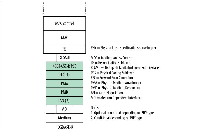
The 40 Gb/s media system defines a physical layer (PHY) that is composed of a set of IEEE sublayers. Figure 1-1 shows the sublayers involved in the PHY. The standard defines an XLGMII logical interface, using the Roman numerals XL to indicate 40 Gb/s. This interface includes a 64-bit-wide path over which frame data bits are sent to the PCS. The FEC and Auto-Negotiation sublayers may or may not be used, depending on the media type involved.
The 100 Gb/s media system defines a physical layer (PHY) that is composed of a set of IEEE sublayers. Figure 1-2 shows the sublayers involved in the PHY. The standard defines a CGMII logical interface, using the Roman numeral C to indicate 100 Gb/s. This interface defines a 64-bit-wide path, over which frame data bits are sent to the PCS. The FEC and AN sublayers may or may not be used, depending on the media type involved.


Figure 1-2
PCS ( Physical Coding Sublayer) LANES
To help meet the engineering challenges of providing 40 Gb/s data flows, the IEEE engineers provided a multilane distribution system for data through the PCS sublayer of the Ethernet interface.
the PCS translates between the respective media independent interface (MII) for each rate and the PMA sublayer. The PCS is responsible for the encoding of data bits into code groups for transmission via the PMA and the subsequent decoding of these code groups from the PMA. The Task Force developed a low‐overhead multilane distribution scheme for the PCS for 40 Gigabit Ethernet and 100 Gigabit Ethernet.
This scheme has been designed to support all PHY types for both 40 Gigabit Ethernet and 100 Gigabit Ethernet. It is flexible and scalable, and will support any future PHY types that may be developed, based on future advances in electrical and optical transmission. The PCS layer also performs the following functions:
- Delineation of frames
- Transport of control signals
- Ensures necessary clock transition density needed by the physical optical and electrical technology
- Stripes and re‐assembles the information across multiple lanes
The PCS leverages the 64B/66B coding scheme that was used in 10 Gigabit Ethernet. It provides a number of useful properties including low overhead and sufficient code space to support necessary code words, consistent with 10 Gigabit Ethernet.

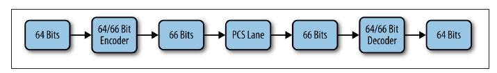
PCS lane for 10 Gb/s Ethernet
The multilane distribution scheme developed for the PCS is fundamentally based on a striping of the 66‐bit blocks across multiple lanes. The mapping of the lanes to the physical electrical and optical channels that will be used in any implementation is complicated by the fact that the two sets of interfaces are not necessarily coupled. Technology development for either a chip interface or an optical interface is not always tied together. Therefore, it was necessary to develop an architecture that would enable the decoupling between the evolution of the optical interface widths and the evolution of the electrical interface widths.
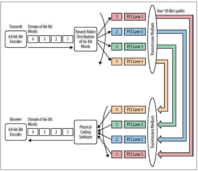
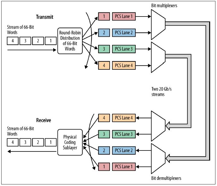
The transmit PCS, therefore, performs the initial 64B/66B encoding and scrambling on the aggregate channel (40 or 100 gigabits per second) before distributing 66‐bit block in a round robin basis across the multiple lanes, referred to as “PCS Lanes,” as illustrated in Figure 2.
The number of PCS lanes needed is the least common multiple of the expected widths of optical and electrical interfaces. For 100 Gigabit Ethernet, 20 PCS lanes have been chosen. The number of electrical or optical interface widths supportable in this architecture is equivalent to the number of factors of the total PCS lanes. Therefore, 20 PCS lanes support interface widths of 1, 2, 4, 5, 10 and 20 channels or wavelengths. For 40 Gigabit Ethernet 4 PCS lanes support interface widths of 1, 2, and 4 channels or wavelengths.

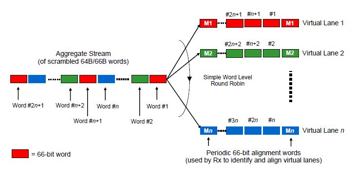
Figure 2- Virtual lane data distribution
Once the PCS lanes are created they can then be multiplexed into any of the supportable interface widths. Each PCS lane has a unique lane marker, which is inserted once every 16,384 blocks. All multiplexing is done at the bit‐level. The round‐robin bit‐level multiplexing can result in multiple PCS lanes being multiplexed into the same physical channel. The unique property of the PCS lanes is that no matter how they are multiplexed together, all bits from the same PCS lane follow the same physical path, regardless of the width of the physical interface. This enables the receiver to be able to correctly re‐assemble the aggregate channel by first de‐multiplexing the bits to re‐assemble the PCS lane and then re‐align the PCS lanes to compensate for any skew. The unique lane marker also enables the de‐skew operation in the receiver. Bandwidth for these lane markers is created by periodically deleting inter‐packet gaps (IPG). These alignment blocks are also shown in Figure 2.
The receiver PCS realigns multiple PCS lanes using the embedded lane markers and then re‐orders the lanes into their original order to reconstruct the aggregate signal.
Two key advantages of the PCS multilane distribution methodology are that all the encoding, scrambling and de‐skew functions can all be implemented in a CMOS device (which is expected to reside on the host device), and minimal processing of the data bits (other than bit muxing) happens in the high speed electronics embedded with an optical module. This will simplify the functionality and ultimately lower the costs of these high‐speed optical interfaces.
The PMA sublayer enables the interconnection between the PCS and any type of PMD sublayer. A PMA sublayer will also reside on either side of a retimed interface, referred to as “XLAUI” (40 gigabit per second attachment unit interface) for 40 Gigabit Ethernet or “CAUI” (100 gigabit per second attachment unit interface) for 100 Gigabit Ethernet.

PCS multilane for 40 Gb/s Ethernet

PCS lanes over a faster media system
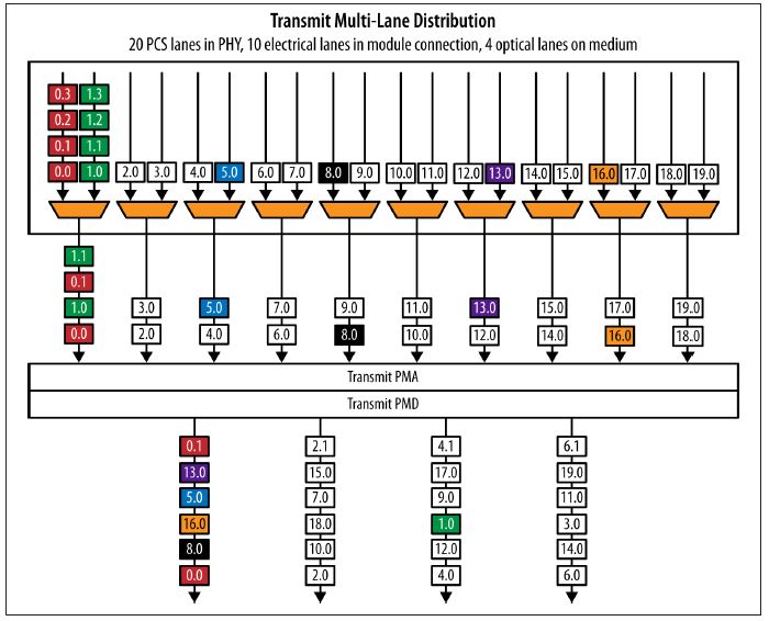
 100 Gb/s multilane transmit operation

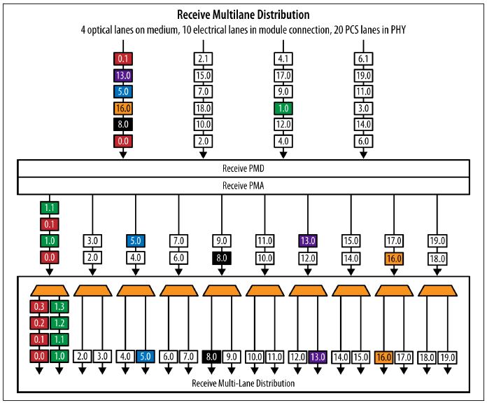
100 Gb/s multi-lane receive operation
Summary
Ethernet has become the unifying technology enabling communications via the Internet and other networks using IP. Its popularity has resulted in a complex ecosystem between carrier networks, data centers, enterprise networks, and consumers with a symbiotic relationship between the various parts.
100 GbE and 40 GbE technologies are rapidly approaching standardization and deployment. A key factor in their success will be ability to utilize existing fiber and copper media in an environment of advancing technologies. The physical coding sublayer (PCS) of the 802.3 architecture is in a perfect position to facilitate this flexibility. The current baseline proposal for PCS implementation uses a unique virtual lane concept that provides the mechanism to handle differing electrical and optical paths.
Notes:64b/66b is a line code that transforms 64-bit data to 66-bit line code to provide enough state changes to allow reasonable clock recovery and facilitate alignment of the data stream at the receiver.
