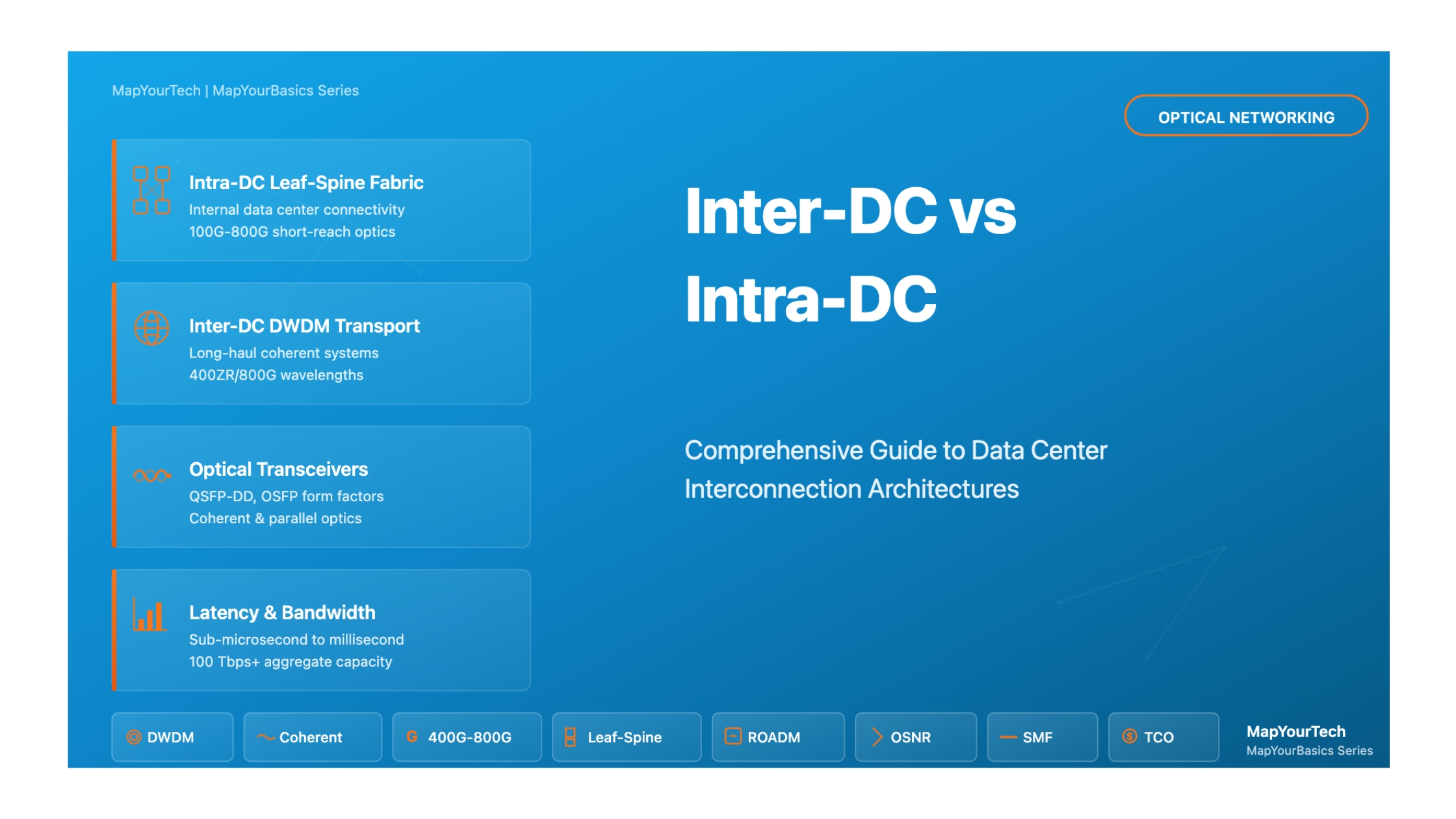

Inter-DC vs Intra-DC for Optical Professionals
A comprehensive guide to understanding data center interconnection architectures, from basic principles to advanced implementations in modern optical networks
Introduction
The explosive growth of cloud computing, artificial intelligence, and distributed applications has fundamentally transformed how organizations design and operate their data center infrastructure. At the heart of this transformation lies a critical distinction that every optical networking professional must understand: the difference between Inter-Data Center (Inter-DC) and Intra-Data Center (Intra-DC) connectivity.
Inter-DC connectivity refers to the networking infrastructure that connects geographically dispersed data centers, enabling seamless communication across metropolitan areas, regions, or even continents. These connections form the backbone of modern cloud services, supporting data replication, disaster recovery, load balancing, and distributed application architectures. In contrast, Intra-DC connectivity encompasses the internal networking fabric within a single data center facility, connecting servers, storage systems, and networking equipment to create a high-performance computing environment.
Why This Distinction Matters
Understanding the fundamental differences between Inter-DC and Intra-DC architectures is crucial for several reasons. First, the physical distances involved dramatically affect design choices regarding optical technologies, protocols, and equipment selection. Second, the performance requirements differ substantially—Intra-DC networks prioritize ultra-low latency and maximum throughput for server-to-server communication, while Inter-DC networks must balance performance with cost-efficiency over longer distances. Third, the economic considerations vary significantly, as Inter-DC links often represent substantial capital and operational expenditures that require careful optimization.
Real-World Relevance and Applications
Modern enterprises and cloud service providers operate in an increasingly distributed computing landscape. A typical large-scale cloud operator maintains multiple data centers across different geographic regions, each containing thousands of servers interconnected through sophisticated Intra-DC networks. These facilities must then communicate with each other through Inter-DC links to provide seamless services to global users.
Consider a content delivery network serving video streaming services. Within each data center (Intra-DC), high-speed optical links connect storage servers to edge routers at speeds of 100 Gbps, 400 Gbps, or even 800 Gbps, using short-reach optics optimized for distances under two kilometers. These connections utilize technologies like direct attach cables, active optical cables, or parallel fiber transceivers designed for maximum density and minimal latency.
Between data centers (Inter-DC), the same provider deploys long-haul coherent optical systems capable of transmitting multiple terabits per second over distances ranging from tens to thousands of kilometers. These systems employ advanced modulation formats, wavelength division multiplexing, and sophisticated error correction to overcome the physical challenges of long-distance transmission.
Industry Applications and Use Cases
The distinction between Inter-DC and Intra-DC connectivity manifests differently across various industry sectors. Financial services organizations require ultra-low latency connections both within and between data centers to support high-frequency trading applications. Healthcare providers must balance performance with regulatory compliance when replicating patient data across geographically distributed facilities. Media and entertainment companies need massive bandwidth to transfer large video files between production and distribution centers.
Cloud service providers face perhaps the most complex challenges, managing both Intra-DC fabrics that scale to support millions of virtual machines and Inter-DC networks that span continents to deliver consistent user experiences worldwide. Their architectural decisions influence the entire industry, driving innovations in optical transceiver technologies, switching architectures, and network automation.
What You'll Learn in This Guide
This comprehensive guide will take you on a journey through both Inter-DC and Intra-DC architectures, covering:
- The historical evolution of data center networking from simple hierarchical designs to modern spine-leaf and Clos architectures
- Core technical concepts including traffic patterns (north-south vs. east-west), network topologies, and optical transmission fundamentals
- Detailed technical architectures for both Intra-DC fabrics and Inter-DC transport networks, including component-level analysis
- Mathematical models for calculating link budgets, capacity planning, and performance optimization
- Classifications of different interconnect types, technologies, and deployment scenarios
- Interactive simulators allowing hands-on exploration of performance tradeoffs and design decisions
- Real-world case studies demonstrating practical implementation approaches and lessons learned
Key Concepts Preview
Before diving into the details, let's preview some fundamental concepts that will recur throughout this guide. Traffic patterns describe how data flows through networks—north-south traffic moves between data centers and external users, while east-west traffic flows between servers within or across data centers. Understanding these patterns is essential for proper capacity planning and architecture design.
Optical reach refers to the maximum distance an optical signal can travel while maintaining acceptable performance. Intra-DC links typically operate over distances under two kilometers using intensity-modulated direct-detection optics, while Inter-DC links may span thousands of kilometers using coherent detection technology.
Bandwidth density measures how much data throughput can be achieved per rack unit of equipment or per square meter of data center space. This metric drives technology choices in both Intra-DC and Inter-DC deployments, as operators seek to maximize capacity while minimizing physical footprint and power consumption.
Latency represents the time delay in signal transmission and processing. Intra-DC applications may require sub-microsecond latencies, while Inter-DC applications must account for both propagation delay (approximately 5 microseconds per kilometer in fiber) and processing delays in intermediate equipment.
With these foundational concepts in mind, we'll now explore the historical context that shaped modern data center interconnection architectures, understanding how the industry evolved from simple beginnings to today's sophisticated multi-tier, multi-site infrastructures supporting the global digital economy.
Visual Architecture Overview
To better understand the distinction between Inter-DC and Intra-DC networking, let's examine visual representations of both architectures:
Intra-DC Network Architecture (Leaf-Spine Topology)
Intra-DC: High-speed internal fabric within a single data center facility using leaf-spine architecture
Inter-DC Network Architecture (Geographic Distribution)
Inter-DC: Long-distance connectivity between geographically distributed data centers using coherent DWDM systems
Key Visual Distinctions
- Intra-DC (Blue/Yellow): Shows the internal network fabric within a single facility. Notice the full mesh connectivity between spine and leaf layers, providing multiple paths for every server-to-server communication. Technologies are optimized for short distances (meters to 2km) with emphasis on low latency and high port density.
- Inter-DC (Red/Orange): Illustrates connectivity between multiple data centers across vast geographic distances. Each data center contains its own Intra-DC fabric, connected through border routers to a DWDM optical transport network. Technologies focus on maximum reach (thousands of kilometers) using sophisticated coherent systems.
- Scale Difference: Intra-DC handles thousands of connections within microseconds of latency, while Inter-DC manages fewer but much longer connections with milliseconds of propagation delay.
Historical Context & Evolution
The Early Days: Hierarchical Data Centers
The evolution of data center networking architectures reflects the broader transformation of computing from centralized mainframes to distributed cloud services. In the early 2000s, data centers primarily followed hierarchical three-tier architectures borrowed from campus networking designs. This traditional approach featured an access layer connecting servers, an aggregation layer providing connectivity between access switches, and a core layer handling inter-switch and external traffic.
These early data centers operated with relatively modest bandwidth requirements—10 Gigabit Ethernet represented cutting-edge performance, and most traffic followed a north-south pattern, flowing between internal servers and external users. The concept of connecting multiple data centers for operational purposes was limited primarily to disaster recovery scenarios, where organizations maintained backup facilities that remained largely dormant until needed.
The Bandwidth Bottleneck Problem
The traditional three-tier architecture worked acceptably when most traffic flowed vertically through the hierarchy. However, as applications became more distributed and service-oriented architectures gained popularity, a fundamental problem emerged: server-to-server traffic within the data center began exceeding external traffic volumes. This east-west traffic had to traverse multiple network layers, creating bottlenecks at aggregation and core switches that limited overall data center performance.
Technology Timeline and Key Milestones
2000-2005: The Foundation Era
During this period, data centers standardized on Gigabit Ethernet for server connections and 10 Gigabit Ethernet for uplinks. Optical networking primarily utilized multimode fiber for short distances and single-mode fiber with 1310nm or 1550nm transmission for longer campus interconnects. The dominant mindset focused on scaling up individual servers rather than scaling out across many smaller systems.
2006-2010: The Web-Scale Revolution
Large internet companies began fundamentally rethinking data center architecture. Research papers from major cloud providers introduced concepts like the Clos topology and leaf-spine architectures that eliminated the bottlenecks inherent in hierarchical designs. These new architectures provided multiple equal-cost paths between any two servers, dramatically increasing aggregate bandwidth and eliminating single points of failure.
During this era, the distinction between Intra-DC and Inter-DC networking began to crystallize. Operators recognized that connecting servers within a facility required different optimization criteria than connecting facilities to each other. Intra-DC links emphasized low latency and high throughput using relatively simple optical technologies, while Inter-DC links needed to efficiently transport traffic over longer distances using more sophisticated transmission techniques.
2011-2015: The Coherent and Pluggable Era
This period witnessed revolutionary advances in both Inter-DC and Intra-DC technologies. For Inter-DC connectivity, 100 Gbps coherent optical transmission became commercially viable, allowing operators to multiplex dozens of high-speed channels onto single fiber pairs. Digital signal processing advances enabled coherent systems to achieve spectral efficiencies previously thought impossible, while simultaneously reducing power consumption and equipment footprint.
For Intra-DC networking, the introduction of 40 Gigabit and 100 Gigabit pluggable transceivers in QSFP form factors transformed network design. These compact modules enabled switches with 32 or more 100G ports in a single rack unit, providing the density needed for modern spine-leaf architectures. Parallel fiber optics using 12 or 24 fiber MPO connectors became standard for cost-effective short-reach connectivity.
2016-2020: Scale-Out and Automation
As data center operators gained experience with leaf-spine architectures, they pushed the boundaries of scale. Individual data centers grew to house tens of thousands of servers, requiring switching fabrics with petabits of aggregate throughput. The concept of the "data center fabric" emerged—a scale-out architecture where additional capacity could be added incrementally by deploying more leaf and spine switches according to standardized designs.
Inter-DC networking evolved similarly, with operators building dedicated optical transport networks optimized specifically for data center interconnection rather than relying on traditional carrier wavelength services. These purpose-built DCI networks employed programmable ROADMs, software-defined networking control, and automation to enable rapid service provisioning and capacity adjustment in response to traffic demands.
Continue Reading This Article
Sign in with a free account to unlock the full article and access the complete MapYourTech knowledge base.
2021-Present: AI Era Demands
The explosion of artificial intelligence and machine learning workloads has driven yet another transformation in data center networking. Training large language models requires unprecedented communication bandwidth between GPU clusters, pushing Intra-DC networks toward 400 Gbps and 800 Gbps per lane technologies. The industry is exploring coherent detection within data centers, a technology previously reserved for Inter-DC links, to achieve the reach and bandwidth needed for AI fabrics.
Inter-DC networking faces similar scaling pressures as organizations distribute AI training across multiple facilities and serve inference workloads from edge locations. Single-wavelength speeds of 400 Gbps and 800 Gbps are becoming standard, with research underway on terabit-per-wavelength transmission. The distinction between Inter-DC and Intra-DC is blurring in some aspects as technologies once exclusive to long-haul networks find applications within data centers.
Pioneer Contributions and Industry Leadership
The evolution of modern data center networking owes much to pioneering work by both academic researchers and industry practitioners. Key contributions include the formalization of Clos network theory for data center applications, the development of ECMP routing for multipath load balancing, and the creation of open networking standards that democratized access to high-performance switching hardware.
Major cloud providers published influential papers describing their network architectures, spurring broader industry adoption of leaf-spine designs. Equipment vendors responded by developing purpose-built data center switches with features optimized for these new topologies, including bufferless switching for low latency and high port density for maximum connectivity.
In the optical domain, the Open Compute Project and related initiatives established specifications for cost-optimized optical transceivers, driving down prices through standardization and volume production. The Optical Internetworking Forum defined interoperability standards like 400ZR for data center interconnection, enabling multi-vendor deployments and fostering competition.
Current State of Technology in 2025
Today's data center interconnection landscape represents a mature yet rapidly evolving ecosystem. Within data centers, 400 Gigabit Ethernet dominates new deployments, using QSFP-DD or OSFP transceiver form factors with eight lanes of 50 Gbps signaling. Short-reach links up to 500 meters typically employ parallel single-mode fiber optics, while longer Intra-DC connections may use wavelength division multiplexing or emerging coherent technologies.
Inter-DC networks predominantly operate at 400 Gbps per wavelength for metro distances, with DWDM systems providing 80 or more wavelength channels per fiber pair. Long-haul networks increasingly deploy 800 Gbps wavelengths and are beginning to trial 1.2 Tbps transmission using advanced modulation formats and ultra-wideband amplification. Open line systems with disaggregated terminal equipment have gained significant traction, offering operators flexibility in technology refresh cycles and multi-vendor sourcing.
Future Outlook
Looking ahead, several trends will shape the next generation of data center interconnection. The convergence of Intra-DC and Inter-DC technologies continues, with coherent optics finding applications in large campus data centers and potentially becoming standard for "super Intra-DC" links beyond two kilometers. Silicon photonics integration promises to bring optical functions closer to compute chips, reducing power consumption and enabling new levels of bandwidth density.
Artificial intelligence will drive demand for both higher speeds and new network architectures. The concept of the "AI data center" may require rethinking traditional designs to support the all-to-all communication patterns characteristic of distributed training. Inter-DC networks will need to support distributed training across geographic locations while maintaining the low latency required for gradient synchronization.
Sustainability considerations are becoming paramount, with operators seeking technologies that maximize performance per watt. This drives interest in co-packaged optics, linear-drive pluggables, and other innovations that reduce the energy overhead of optical transmission. The industry recognizes that continued scaling must be achieved with improved energy efficiency to remain environmentally and economically viable.
Core Concepts & Fundamentals
Understanding Traffic Patterns in Data Centers
The fundamental distinction between Inter-DC and Intra-DC architectures stems from the nature of traffic they must support. Traffic patterns in modern data centers have evolved dramatically from the simple client-server models of the past, and understanding these patterns is crucial for optimal network design.
North-South vs East-West Traffic
North-South Traffic refers to data flows between resources inside the data center and external entities—users accessing applications over the internet, connections to partner networks, or communications with other data centers. This traffic crosses the data center boundary, typically passing through border routers and firewalls. Historically, north-south traffic dominated data center bandwidth requirements, as servers primarily responded to external requests.
East-West Traffic describes communications between servers and systems within the data center or across multiple data centers within the same organization. Modern distributed applications generate enormous amounts of east-west traffic as application tiers communicate, databases replicate, and services coordinate through APIs. Industry studies indicate that east-west traffic now accounts for 75-85% of total data center bandwidth, fundamentally changing network design priorities.
Traffic Pattern Implications
The dominance of east-west traffic drove the adoption of leaf-spine architectures for Intra-DC networks. Traditional hierarchical designs created bottlenecks for east-west flows that had to traverse multiple switch hops. Leaf-spine architectures provide consistent, low-latency paths for server-to-server communication regardless of physical location within the data center. For Inter-DC networks, the need to efficiently transport both north-south traffic (users accessing services) and east-west traffic (data replication and distributed applications) influences capacity planning and routing design.
Fundamental Network Topologies
Intra-DC Topologies: Leaf-Spine Architecture
The leaf-spine topology has become the de facto standard for modern data center networks. In this architecture, every leaf switch (typically top-of-rack switches directly connected to servers) connects to every spine switch, creating a two-tier Clos network. This design provides multiple equal-cost paths between any two servers, enabling efficient load balancing and eliminating single points of failure.
Key characteristics of leaf-spine architectures include:
- Predictable Latency: Any server-to-server path traverses exactly one leaf, one spine, and one leaf switch, resulting in consistent latency regardless of source and destination
- Linear Scalability: Capacity scales by adding leaf switches (for more servers) or spine switches (for more bandwidth)
- No Spanning Tree: The use of equal-cost multipath routing eliminates the need for spanning tree protocol and its associated link waste
- High Bisection Bandwidth: Properly provisioned leaf-spine networks achieve 1:1 oversubscription, meaning aggregate server capacity equals uplink capacity
Variants of the basic leaf-spine design include multi-tier Clos networks for very large deployments and specialized topologies optimized for specific workloads such as AI training clusters.
Inter-DC Topologies: Mesh and Hub-Spoke
Inter-DC network topologies depend heavily on geographic distribution and traffic patterns. Organizations with data centers in close proximity often deploy full mesh connectivity, where every data center connects directly to every other data center. This approach minimizes latency and provides maximum redundancy but scales poorly as the number of sites increases.
For organizations with many distributed sites, hub-and-spoke topologies offer better economics. Regional hubs with high-capacity interconnections exchange traffic between spoke sites, reducing the total number of required circuits. However, this introduces additional latency for spoke-to-spoke communication and creates potential bottlenecks at hub locations.
Many large operators employ hybrid approaches—full mesh connectivity between major regional data centers combined with hub-spoke designs for smaller edge facilities. Advanced traffic engineering using MPLS or segment routing enables dynamic path selection based on real-time network conditions and policy requirements.
Optical Transmission Fundamentals
Short-Reach vs Long-Reach Optics
The physical distance of optical links fundamentally determines technology choices. Short-reach optics, typically used for Intra-DC connectivity, optimize for cost and power efficiency over distances up to two kilometers. These transceivers use directly modulated lasers and simple photodetectors, achieving high speeds through parallel fiber transmission (multiple wavelengths or fibers carrying separate data streams) and advanced modulation formats like PAM4.
Long-reach optics for Inter-DC applications must overcome chromatic dispersion, polarization mode dispersion, and fiber attenuation over tens to thousands of kilometers. These systems employ coherent detection, using optical local oscillators and balanced receivers to detect both amplitude and phase information. Digital signal processing compensates for transmission impairments, enabling spectral efficiencies approaching theoretical limits.
Key Performance Metrics
Latency Considerations
Latency—the time delay between sending and receiving data—manifests differently in Intra-DC and Inter-DC networks. Intra-DC latency consists primarily of switching delay (typically 300-500 nanoseconds per switch) and short propagation delays (about 5 nanoseconds per meter in fiber). Modern data center networks target total latencies under 10 microseconds for server-to-server communication within the same facility.
Inter-DC latency is dominated by propagation delay, which cannot be reduced below the fundamental limit imposed by the speed of light in fiber (approximately 5 microseconds per kilometer). Additional contributions come from optical transponders (potentially tens of microseconds with forward error correction) and intermediate routing nodes. Metro DCI links might add 500 microseconds for a 100-kilometer span, while transcontinental links introduce tens of milliseconds.
Bandwidth and Throughput
Bandwidth represents the theoretical maximum data rate, while throughput measures actual achieved performance. In Intra-DC networks, switches typically deliver near-theoretical throughput due to minimal packet loss and latency. Network operators target 1:1 oversubscription ratios, where the total server-facing bandwidth equals uplink capacity, ensuring full bandwidth availability for east-west traffic.
Inter-DC throughput depends on numerous factors including distance, optical signal-to-noise ratio, and network congestion. Coherent systems dynamically adjust modulation formats and forward error correction to optimize throughput for prevailing conditions. A 400G wavelength might operate at 400 Gbps over short metro distances but adjust to 300 Gbps or lower for longer reaches to maintain acceptable error rates.
Conceptual Models and Frameworks
The Data Center Fabric Concept
Modern thinking treats the Intra-DC network as a unified "fabric"—a consistent, scalable infrastructure that abstracts physical topology from applications. This conceptual model emphasizes several key principles:
- Location Independence: Applications should not depend on the physical location of servers or services within the data center
- Elastic Scaling: Capacity grows incrementally by adding standardized building blocks rather than requiring forklift upgrades
- Resilience Through Redundancy: Multiple parallel paths provide inherent fault tolerance without complex failover mechanisms
- Simplified Operations: Standardized configurations and automation reduce operational complexity despite increasing scale
The Inter-DC Transport Network Model
Inter-DC connectivity increasingly operates as a dedicated optical transport network separate from traditional WAN services. This "DC fabric" model extends across multiple sites, providing high-capacity Layer 1 or Layer 2 connectivity that appears as a local network extension to applications. Key aspects include:
- Service Independence: Applications communicate as if all data centers were local, with the transport network handling geographic distribution transparently
- Bandwidth on Demand: Software-defined networking enables dynamic provisioning of optical circuits as traffic patterns evolve
- Integrated Management: Common control planes coordinate both Intra-DC and Inter-DC resources for end-to-end optimization
- Cost Optimization: Purpose-built DCI networks achieve better cost per bit than purchasing wavelength services from carriers
Understanding Network Layers and Protocols
Data center networks implement distinct protocol strategies at different layers. At Layer 1, optical transmission technologies provide physical connectivity. Layer 2 protocols (primarily Ethernet) handle local switching and forwarding. Layer 3 routing protocols (such as BGP and OSPF) manage inter-subnet communication and external connectivity.
In Intra-DC networks, Layer 2 generally extends only within racks or small pod structures, with Layer 3 routing used for most internal traffic. This approach avoids the scaling limitations of large Layer 2 broadcast domains while maintaining simple, predictable behavior. Inter-DC networks may employ Layer 2 extension for specific use cases like virtual machine migration, but increasingly rely on Layer 3 routing with overlay tunneling protocols for greater flexibility.
With these fundamental concepts established, we can now examine the detailed technical architectures that implement Inter-DC and Intra-DC connectivity in production networks, exploring the specific components, protocols, and design patterns that enable modern data center operations.
Technical Architecture & Components
Intra-DC Network Architecture Deep Dive
Leaf-Spine Physical Architecture
A production-scale leaf-spine architecture consists of multiple layers of specialized switching hardware. At the access layer, top-of-rack switches connect directly to servers using copper or short-reach optical connections. Modern ToR switches typically provide 32 to 64 ports of 100 Gigabit Ethernet or 400 Gigabit Ethernet downlink connectivity, with additional uplink ports connecting to spine switches.
The typical port configuration for a ToR switch might include 32 ports of 400GbE facing servers and 16 ports of 400GbE as uplinks, providing 2:1 oversubscription (12.8 Tbps server bandwidth with 6.4 Tbps uplink capacity). Higher-performance designs achieve 1:1 oversubscription by matching total server and uplink bandwidth.
Spine switches form the aggregation layer, providing high-radix switching to interconnect all leaf switches. A spine switch might offer 64 to 128 ports of 400 Gigabit or 800 Gigabit Ethernet, each connecting to a different leaf switch. The number of spine switches determines the bandwidth available between leaf pairs—more spine switches provide more parallel paths and greater aggregate capacity.
Scaling Example
Consider a data center with 1,000 server racks, each requiring 6.4 Tbps of bandwidth (32 x 200G). Using leaf switches with 32 x 200G downlinks and 16 x 400G uplinks, we need 1,000 leaf switches. To provide full bandwidth (1:1 oversubscription), we need 32 spine switches, each with 1,000 x 400G ports. This creates 32,000 spine-to-leaf links totaling 12.8 Petabits of bisection bandwidth.
Optical Components in Intra-DC Networks
Intra-DC optical connectivity relies on several transceiver types optimized for different reach requirements:
- Direct Attach Cables (DAC): For connections under 5 meters, passive copper cables provide the lowest cost and power consumption. Active copper cables extend reach to 7-10 meters with signal regeneration.
- Active Optical Cables (AOC): Integrated fiber cables with permanently attached transceivers serve distances up to 100 meters, offering better power efficiency than copper for longer runs.
- Parallel Fiber Transceivers: QSFP and OSFP modules using MPO connectors support 100G to 800G speeds over multimode or single-mode fiber for distances up to 500 meters.
- WDM Transceivers: For longer Intra-DC links beyond 500 meters, wavelength division multiplexing enables higher speeds over fewer fibers, using either coarse WDM (CWDM) or dense WDM (DWDM) technologies.
The fiber plant within data centers typically employs structured cabling with trunk cables running between switch locations and jumper cables connecting equipment to patch panels. Proper cable management and labeling are critical for maintaining operation as networks scale to thousands of connections.
Inter-DC Network Architecture Deep Dive
DWDM Transport Systems
Inter-DC optical networks predominantly employ dense wavelength division multiplexing to maximize fiber capacity. A modern DWDM system might transmit 96 wavelength channels spaced at 50 GHz or 75 GHz intervals across the C-band spectrum, with each channel carrying 400 Gbps or more. This enables total fiber capacity exceeding 38 Terabits per second on a single fiber pair.
The fundamental components of an Inter-DC DWDM system include:
Coherent Transponders: These sophisticated optical transmitters and receivers convert client signals (typically Ethernet) into wavelength-specific optical carriers. Modern coherent transponders employ 64-QAM or higher modulation formats, probabilistic constellation shaping, and powerful forward error correction to maximize reach and spectral efficiency. Pluggable coherent modules in QSFP-DD or OSFP form factors are increasingly popular for metro DCI applications.
Reconfigurable Optical Add-Drop Multiplexers (ROADMs): These devices enable flexible wavelength routing without optical-electrical-optical conversion. A typical degree-4 ROADM node can add, drop, or pass through wavelengths to four different directions. Modern "colorless, directionless, contentionless" (CDC) ROADM designs provide maximum flexibility by allowing any wavelength to be added or dropped at any port without wavelength contention issues.
Optical Amplifiers: Erbium-doped fiber amplifiers (EDFAs) compensate for fiber loss and component insertion loss, enabling transmission over extended distances. For metro DCI, amplifiers might be deployed every 80-100 kilometers. Ultra-long-haul systems use distributed Raman amplification to minimize noise accumulation.
Optical Line System (OLS): This encompasses the fiber plant, amplifiers, dispersion compensation (where needed), and monitoring equipment that forms the physical transmission path. The trend toward disaggregated OLS architectures separates terminal equipment from line system components, enabling independent optimization and multi-vendor sourcing.
IP/MPLS Layer for Inter-DC
Above the optical transport layer, Inter-DC networks typically implement IP routing or MPLS label switching for traffic engineering and service delivery. Border routers in each data center terminate optical wavelengths and provide packet switching functionality.
Key routing technologies include:
- BGP with MPLS VPNs: Enables isolated Layer 3 connectivity for different tenants or applications sharing the same physical infrastructure
- EVPN-VXLAN: Provides Layer 2 extension across data centers while maintaining Layer 3 boundaries, useful for virtual machine mobility
- Segment Routing: Simplifies traffic engineering by encoding forwarding paths in packet headers rather than maintaining per-flow state in routers
- Multipath Protocols: Equal-cost multipath (ECMP) load balancing distributes traffic across parallel Inter-DC links for maximum bandwidth utilization
Detailed Component Analysis
| Component Type | Intra-DC Application | Inter-DC Application | Key Differences |
|---|---|---|---|
| Optical Transceivers | Short-reach IM-DD, parallel fiber, 100-800G | Coherent detection, WDM, 400-800G per λ | Reach vs cost optimization, modulation complexity |
| Switches/Routers | Merchant silicon, low latency, high density | High-capacity routers, deep buffers, QoS | Latency vs feature richness trade-offs |
| Fiber Type | OM4/OM5 multimode or single-mode | Single-mode fiber, low-loss variants | Distance requirements drive fiber selection |
| Network Topology | Leaf-spine Clos networks | Mesh, ring, or hub-spoke with ROADM | Scale-out vs resilience optimization |
| Control Plane | IGP routing (OSPF/IS-IS), SDN controllers | BGP, MPLS, optical control plane | Simplicity vs policy richness |
Data Flows and Interactions
Intra-DC Data Flows
Consider a typical application transaction within a data center. A web request arrives at a load balancer, which selects an application server. The application server queries a database cluster, potentially accessing both memory caches and persistent storage. This single user transaction might generate dozens of internal network flows as microservices communicate.
The packet flow follows a consistent pattern: from server to ToR leaf switch (one hop), to spine switch (one hop), to destination leaf switch (one hop), to destination server. Total switching latency remains under two microseconds with modern low-latency switches. The leaf-spine architecture ensures all server pairs can communicate at full link speed simultaneously if properly provisioned.
Inter-DC Data Flows
Inter-DC traffic follows a more complex path. Within the source data center, packets route from servers through the Intra-DC fabric to border routers. These routers forward traffic to Inter-DC optical transponders, which modulate the data onto wavelengths in the DWDM system. The optical signal traverses multiple fiber spans and amplifiers before reaching the destination data center's optical terminal equipment, where it undergoes optical-electrical conversion, routing through the destination border router, and finally delivery through the Intra-DC fabric to target servers.
Advanced traffic engineering optimizes this path based on multiple criteria: link utilization, latency requirements, quality of service policies, and cost considerations (such as preferring owned infrastructure over leased capacity). Software-defined networking controllers can dynamically adjust routing based on real-time network conditions.
Protocols and Standards
Intra-DC Protocol Stack
Modern Intra-DC networks employ a simplified protocol stack focused on performance and operational simplicity:
- Layer 2: Ethernet with jumbo frames (9000 byte MTU) for improved efficiency
- Layer 3: IPv4/IPv6 routing with ECMP load balancing across spine switches
- Routing Protocols: OSPF or BGP with equal-cost multipath for simple, predictable convergence
- Overlay Protocols: VXLAN or Geneve for network virtualization and tenant isolation
- Management: OpenFlow, P4, or vendor APIs for software-defined control
Inter-DC Protocol Stack
Inter-DC networks implement richer protocol functionality to support diverse service requirements:
- Optical Layer: ITU-T G.698.2 for DWDM applications, OIF 400ZR for pluggable coherent interfaces
- Layer 2: Ethernet with IEEE 802.1Q VLAN tagging, 802.1ad provider bridging for service isolation
- Layer 3: BGP for inter-domain routing, OSPF or IS-IS for intra-domain routing
- MPLS: Label switching for traffic engineering and VPN services
- Transport: TCP optimization with selective acknowledgment, window scaling for high bandwidth-delay products
Implementation Layers
Both Intra-DC and Inter-DC architectures separate concerns across multiple implementation layers. The physical layer provides optical transmission. The link layer handles local switching and forwarding. The network layer implements routing and addressing. The control plane manages configuration and monitors operational state. The management plane provides human interfaces for provisioning and troubleshooting.
This layered approach enables independent evolution of different functional areas. For example, optical transceiver technology can advance without requiring changes to switching hardware, provided interfaces remain compatible. Similarly, control plane software can be enhanced to implement new features while maintaining consistent hardware behavior.
With the architectural foundations established, we now turn to the mathematical models that guide capacity planning, performance analysis, and optimization of both Intra-DC and Inter-DC networks. Understanding these quantitative relationships is essential for translating business requirements into technical specifications.
Mathematical Models & Formulas
Link Budget Calculations for Optical Systems
Optical Power Budget
The fundamental equation for optical link budget analysis determines if a link will operate successfully:
P_receiver = P_transmitter - Loss_total + Gain_total

Where:
  P_receiver     = Power at receiver (dBm)
  P_transmitter  = Power at transmitter (dBm)
  Loss_total     = Sum of all losses (dB)
  Gain_total     = Sum of all gains (dB)
Loss Components include:
- Fiber attenuation: α × L (typically 0.2 dB/km at 1550nm)
- Connector losses: 0.3-0.5 dB per connector pair
- Splice losses: 0.05-0.1 dB per splice
- Mux/Demux insertion loss: 3-6 dB per device
- ROADM insertion loss: 5-12 dB per node
Intra-DC Link Budget Example
For a 500-meter connection within a data center using 100G-SR4 transceivers:
- Transmit power: -2 dBm per lane
- Fiber loss: 0.5 km × 2.5 dB/km = 1.25 dB (multimode fiber)
- Connector loss: 2 connectors × 0.5 dB = 1.0 dB
- Total loss: 2.25 dB
- Received power: -2 - 2.25 = -4.25 dBm
- Receiver sensitivity: -9 dBm
- Link margin: -4.25 - (-9) = 4.75 dB (acceptable)
OSNR (Optical Signal-to-Noise Ratio) Calculation
For coherent Inter-DC systems, OSNR determines maximum reach:
OSNR = P_signal - P_noise - 10×log₁₀(B_ref)

Where:
  P_signal  = Signal power (dBm)
  P_noise   = Noise power in reference bandwidth (dBm)
  B_ref     = Reference bandwidth (typically 0.1 nm or 12.5 GHz)

Minimum OSNR required (at BER = 10⁻¹⁵):
  • QPSK:   ~11 dB
  • 16-QAM: ~17 dB
  • 64-QAM: ~24 dB
Capacity Planning and Dimensioning
Intra-DC Bandwidth Requirements
Total_Bandwidth = N_servers × B_server / Oversubscription_ratio

Where:
  N_servers              = Number of servers
  B_server               = Bandwidth per server
  Oversubscription_ratio = Server BW / Uplink BW (target: 1:1 to 3:1)

Number of Spine Switches needed:
N_spine = (N_leaf × B_uplink_leaf) / B_downlink_spine

Where:
  N_leaf             = Number of leaf switches
  B_uplink_leaf      = Uplink bandwidth per leaf
  B_downlink_spine   = Downlink bandwidth per spine
Practical Example: A data center with 2,000 servers at 100 Gbps each requires 200 Tbps total server bandwidth. Using 1:1 oversubscription, we need 200 Tbps of spine-leaf capacity. With leaf switches having 32×100G downlinks and 8×400G uplinks (3.2 Tbps down, 3.2 Tbps up), we need 2000/32 = 63 leaf switches. Each leaf has 3.2 Tbps uplink capacity, totaling 201.6 Tbps. Using spine switches with 64×400G ports (25.6 Tbps), we need 8 spine switches to provide 204.8 Tbps total capacity.
Inter-DC Capacity Planning
Required_DCI_Bandwidth = Traffic_replication + Traffic_migration +
                         Traffic_distributed_apps + Growth_margin

Traffic_replication = Data_size × Replication_factor / Time_window

For N data centers with full mesh connectivity:
Total_Wavelengths = N × (N-1) × Wavelengths_per_pair / 2

Fiber_Pair_Requirements = Total_Wavelengths / Wavelengths_per_fiber
Performance Modeling
Latency Calculation
Total_Latency = Propagation_delay + Processing_delay +
                Queuing_delay + Serialization_delay

Propagation_delay = Distance / Speed_of_light_in_fiber
                  = Distance_km / 200,000 km/s
                  ≈ 5 μs per kilometer

Processing_delay_switch = 0.3 to 0.5 μs per switch
Processing_delay_router = 5 to 50 μs depending on features

Serialization_delay = Packet_size_bits / Link_speed_bps

For Intra-DC (500m, 2 switches):
Total = (0.5/200,000)×10⁶ + 2×0.5 + minimal queuing + serialization
      ≈ 2.5 + 1.0 + 0.1 + 0.05 = 3.65 μs

For Inter-DC (100km, coherent transponder):
Total = (100/200,000)×10⁶ + 2×20 + minimal + serialization
      ≈ 500 + 40 + 1 + 0.05 = 541 μs
Spectral Efficiency and Modulation
Shannon Capacity Limit
C = B × log₂(1 + SNR)

Where:
  C   = Channel capacity (bits/second)
  B   = Bandwidth (Hz)
  SNR = Signal-to-noise ratio (linear, not dB)

For coherent systems with dual polarization:
Spectral_Efficiency = Bit_rate / (Symbol_rate × 2)
                    = log₂(M) bits/symbol

Where M is modulation order:
  QPSK:   M=4,  SE=2 bits/symbol
  16-QAM: M=16, SE=4 bits/symbol
  64-QAM: M=64, SE=6 bits/symbol
Power Consumption Models
Network Power Calculation
Power_Intra_DC = N_switches × (P_base + N_ports × P_per_port +
                               N_transceivers × P_transceiver)

Typical values:
  P_base        = 200-500 W (switch ASIC and fans)
  P_per_port    = 2-5 W (electrical circuitry)
  P_transceiver = 3-15 W depending on speed and reach

Power_Inter_DC = N_transponders × P_transponder +
                 N_amplifiers × P_amplifier +
                 N_ROADMs × P_ROADM

Typical values:
  P_transponder_coherent = 50-150 W
  P_amplifier_EDFA      = 30-50 W
  P_ROADM               = 100-300 W per degree

Power_per_bit = Total_power / Total_throughput_bps
              (Target: <5 pJ/bit for Intra-DC, <10 pJ/bit for Inter-DC)
Reliability and Availability Calculations
System Availability
Availability = MTBF / (MTBF + MTTR)

Where:
  MTBF = Mean Time Between Failures
  MTTR = Mean Time To Repair

For redundant systems (parallel configuration):
A_system = 1 - (1 - A₁) × (1 - A₂)

For example, two 99.9% available paths:
A_system = 1 - (1 - 0.999) × (1 - 0.999)
         = 1 - 0.001 × 0.001
         = 0.999999 (99.9999% or "five nines")

For series systems:
A_system = A₁ × A₂ × ... × Aₙ
Economic Models
Total Cost of Ownership (TCO)
TCO = CAPEX + (OPEX × Years)

CAPEX = Equipment_cost + Installation_cost + Fiber_cost

OPEX_annual = Power_cost + Space_cost + Maintenance_cost +
              Personnel_cost

Power_cost = Power_consumption_kW × Hours_per_year ×
             Cost_per_kWh × PUE

Cost_per_bit_km = TCO / (Bandwidth × Distance × Years)

This metric enables comparison between:
  • Building vs. leasing Inter-DC capacity
  • Different optical technology choices
  • Network topology alternatives
Practical Application of Mathematical Models
These mathematical models guide real-world design decisions. When planning an Intra-DC network, link budget calculations verify that chosen transceivers will operate reliably at required distances. Capacity planning formulas determine how many switches of each type to deploy for target performance levels. Power consumption models help optimize equipment selection for minimal operational cost.
For Inter-DC networks, OSNR calculations determine maximum reach for each modulation format, guiding decisions about amplifier spacing and wavelength counts. Economic models compare building dedicated fiber infrastructure versus purchasing capacity from carriers. Availability calculations justify redundancy investments by quantifying downtime reduction.
Modern network planning tools incorporate these mathematical models into automated design workflows. Engineers specify requirements (bandwidth, latency, availability), and software generates optimized designs with detailed bill of materials, power budgets, and cost projections. However, understanding the underlying mathematics remains essential for validating automated results and making informed decisions when edge cases arise.
Types, Variations & Classifications
Classification of Intra-DC Interconnects
By Distance and Technology
| Type | Distance Range | Technology | Typical Use Case | Cost/Power |
|---|---|---|---|---|
| Very Short Reach (VSR) | 0-5 meters | DAC copper cables | Within-rack or adjacent rack connections | Lowest cost, lowest power (0.5W) |
| Short Reach (SR) | 10-100 meters | Multimode fiber with VCSEL | ToR to spine, same row | Low cost, low power (3-5W) |
| Medium Reach (DR/FR) | 100-500 meters | Single-mode fiber, parallel optics | Across data center zones | Medium cost, medium power (5-8W) |
| Long Reach (LR) | 500m-2km | CWDM or DWDM on SMF | Campus interconnect, large facilities | Higher cost, higher power (8-12W) |
| Extended Reach (ER/ZR) | 2-10km | Coherent detection | Multi-building campus, emerging | Highest cost, highest power (12-15W) |
By Form Factor and Integration
Pluggable Transceivers: The dominant approach uses hot-swappable modules in standardized form factors—SFP, QSFP, QSFP28, QSFP56, QSFP-DD, and OSFP. These modules can be replaced without powering down switches, enabling technology upgrades and reducing sparing requirements.
Active Optical Cables (AOC): These integrated assemblies combine transceivers with attached fiber cables, optimized as complete units. AOCs simplify deployment and reduce connector loss but lack flexibility for fiber plant changes.
Mid-Board Optics: An emerging approach mounts optical engines directly on switch PCBs, closer to the switching ASIC. This reduces electrical path length and power consumption but complicates maintenance and thermal management.
Co-Packaged Optics (CPO): The ultimate integration places optical components in the same package as the switch ASIC, enabling massive bandwidth density with minimal power. CPO remains primarily in research but promises transformative benefits for future data centers.
Classification of Inter-DC Interconnects
By Geographic Scope
| Classification | Distance | Technology | Latency | Primary Application |
|---|---|---|---|---|
| Campus DCI | 0-10 km | Dark fiber with gray or CWDM | <50 μs | High-availability clusters, storage replication |
| Metro DCI | 10-100 km | DWDM with pluggable coherent | 50-500 μs | Regional redundancy, disaster recovery |
| Regional DCI | 100-1000 km | High-performance coherent systems | 0.5-5 ms | Multi-region services, content distribution |
| Long-Haul DCI | 1000+ km | Ultra-long-haul coherent with Raman | >5 ms | Transcontinental backup, global services |
| Subsea DCI | 1000-20000 km | Submarine cable systems | 5-100 ms | International connectivity, intercontinental |
By Service Model
Dark Fiber Model: Organizations lease or own raw fiber and deploy their own transmission equipment. This provides maximum control and lowest long-term cost but requires significant capital investment and technical expertise. Best suited for high-volume, long-term requirements.
Wavelength Services: Carriers provide dedicated wavelengths (lambdas) with specified bandwidth and reach. The carrier manages the optical infrastructure while customers control Layer 2/3 networking. This model offers good economics for moderate bandwidth needs without requiring optical expertise.
Ethernet Private Line: Carriers deliver port-to-port Ethernet connectivity at specified rates (1G, 10G, 100G). Customers interact only with Ethernet interfaces while carriers handle all underlying optical transport. Simplest model but typically highest per-bit cost.
MPLS VPN Services: Layer 3 connectivity with any-to-any reachability through carrier MPLS networks. Provides built-in quality of service and traffic engineering but less suitable for large bandwidth requirements due to cost structure.
Comparison of Network Architectures
| Architecture | Advantages | Disadvantages | Best Use Cases |
|---|---|---|---|
| Leaf-Spine (Intra-DC) |
• Predictable latency • Linear scalability • High bisection bandwidth • Simple operations |
• Limited to 2-tier • Fixed radix constraints • Requires many fibers |
General-purpose data centers with scale-out workloads |
| Dragonfly (HPC) |
• Extreme scalability • Reduced network diameter • Lower total cable count |
• Complex routing • Potential congestion • Workload sensitive |
Supercomputing, AI training clusters with structured communication |
| Full Mesh (Inter-DC) |
• Minimal latency • Maximum redundancy • Simple path selection |
• Poor scalability (N² links) • High cost • Complex management |
3-5 data centers with high inter-site traffic |
| Hub-Spoke (Inter-DC) |
• Good scalability • Centralized management • Lower link count |
• Hub bottleneck • Increased latency • Hub single point of failure |
Many distributed sites with centralized services |
| Ring with ROADM (Inter-DC) |
• Built-in protection • Wavelength flexibility • Moderate cost |
• Limited by ring size • Protection switching delay • Accumulated OSNR degradation |
Metro/regional data centers with shared fiber paths |
Decision Matrix for Architecture Selection
Choose Intra-DC Leaf-Spine when:
- Building or refreshing single-site data center fabric
- Need predictable performance for diverse workloads
- Require ability to scale incrementally
- Operations team has standard networking skills
Choose Inter-DC Full Mesh when:
- Connecting 3-5 major data center sites
- Inter-site traffic is high and bidirectional
- Latency minimization is critical
- Budget supports dedicated links between all site pairs
Choose Inter-DC Hub-Spoke when:
- Connecting many (>10) distributed sites
- Traffic patterns are primarily hub-centric
- Cost optimization is more important than minimal latency
- Acceptable to concentrate traffic through regional hubs
Hybrid Architectures
Modern large-scale deployments often combine multiple architectural patterns. A typical global cloud provider might implement:
- Leaf-spine fabrics within each data center for Intra-DC connectivity
- Full mesh DWDM between 3-4 major regional hubs using owned fiber
- Hub-spoke connections from hubs to smaller edge sites using carrier wavelength services
- Direct peering connections to major internet exchanges and CDNs
- Software-defined overlay networks to abstract physical topology from applications
This hybrid approach optimizes different aspects of the network independently—performance where critical, cost where acceptable, and flexibility through software abstraction. The key is maintaining consistent interfaces and management systems across the diverse underlying infrastructure.
Interactive Simulators
Simulator 1: Intra-DC Link Budget Calculator
Calculate optical power budget for data center interconnects. Adjust parameters to see real-time impact on link margin and viability.
Simulator 2: Inter-DC vs Intra-DC Performance Comparison
Compare key performance metrics between Intra-DC and Inter-DC architectures based on distance and configuration.
Simulator 3: Leaf-Spine Capacity Planning Tool
Calculate required spine switches and total bandwidth for your Intra-DC network design.
Simulator 4: TCO and Power Consumption Analyzer
Analyze total cost of ownership and power consumption for Inter-DC and Intra-DC networks.
Practical Applications & Case Studies
Real-World Deployment Scenarios
Scenario 1: Global Cloud Provider Multi-Region Deployment
Challenge: A major cloud service provider operates 15 data centers across 5 geographic regions, serving millions of users worldwide. They need to support seamless virtual machine migration, real-time data replication, and global content delivery while maintaining service-level agreements for latency and availability.
Solution Approach:
- Intra-DC: Deployed 400G leaf-spine architectures in each facility with 1:1 oversubscription. Each data center contains 50-100 leaf switches connecting 3,000-6,000 servers, interconnected through 16-32 spine switches providing 200+ Tbps bisection bandwidth.
- Regional Inter-DC: Implemented full-mesh DWDM networks between the 3-4 data centers within each region using owned fiber and 400G coherent wavelengths. Each regional mesh provides 6-12 Tbps of inter-site capacity.
- Inter-Regional DCI: Connected regions through hub-and-spoke topology using 200G and 400G wavelength services from multiple carriers for redundancy. Primary hubs in each region aggregate traffic for cross-region distribution.
Results and Benefits: The deployment achieved 99.999% availability for critical services through geographic redundancy. VM migration times decreased by 70% with dedicated high-bandwidth Inter-DC links. Total network capacity scaled from 50 Tbps to 300+ Tbps over three years through incremental additions. Cost per transported gigabyte decreased by 60% compared to previous architecture using carrier MPLS services.
Scenario 2: Financial Services High-Frequency Trading Infrastructure
Challenge: A financial services firm required ultra-low-latency connectivity between their primary trading data center, disaster recovery site 50km away, and colocation presence at multiple exchanges. Latency budgets of <500 microseconds for critical paths drove all design decisions.
Solution Approach:
- Intra-DC: Implemented custom leaf-spine design using low-latency merchant silicon switches with cut-through forwarding. Servers connect via 25G DAC cables for minimum latency. All switches operate bufferless to eliminate queuing delay. Achieved consistent 1.2 microsecond server-to-server latency.
- Campus Inter-DC: Deployed four parallel dark fiber pairs between primary and DR sites with gray optics operating at 100G each. No intermediate optical equipment—direct point-to-point connections minimize processing delay. Total end-to-end latency including propagation: 260 microseconds.
- Exchange Connectivity: Leased dedicated fiber to each exchange colocation, deploying ultra-low-latency WDM terminals. Implemented diverse physical paths for redundancy without sacrificing latency.
Results and Benefits: Achieved target latency budgets for all critical paths. During testing, order execution times improved by 40 microseconds compared to previous generation infrastructure. The low-latency DR connectivity enabled active-active trading operations across sites, improving resilience. Geographic diversity provided by DR site and exchange connections eliminated single points of failure while maintaining performance requirements.
Scenario 3: Media & Entertainment Content Distribution Network
Challenge: A streaming media provider needed to distribute 4K and emerging 8K video content to edge caching servers across 100+ locations worldwide. Peak traffic events (premieres, live sports) generate sustained 100+ Gbps flows that must be replicated to multiple sites simultaneously. Storage requirements mandate frequent large file transfers between production and distribution centers.
Solution Approach:
- Intra-DC: Built high-bandwidth fabrics in four primary production/distribution centers using 400G leaf-spine networks. Implemented 800G uplinks on spine switches to handle sustained high-volume flows from storage arrays to content delivery networks.
- Core Inter-DC Mesh: Deployed 400G DWDM mesh between the four core sites with 48+ wavelengths per fiber pair, providing 19+ Tbps of full-duplex capacity on each link. Implemented diverse fiber routes and dual-homed sites for resilience against fiber cuts.
- Edge Site Connectivity: Connected 100+ edge caching locations through hub-spoke design using combination of owned metro fiber (major cities) and carrier wavelength services (secondary markets). Implemented intelligent content routing to optimize delivery paths based on real-time network conditions.
Results and Benefits: Successfully supported record-breaking simultaneous viewership during major live events without degradation. Large file transfer times (multi-terabyte productions) reduced from hours to minutes. Geographic distribution of content completed 3x faster, enabling later content finalization and earlier release. Cost per delivered gigabyte decreased 45% through efficient use of owned infrastructure versus carrier services. System automatically reroutes around failures with no viewer impact.
Troubleshooting Guide
| Problem | Symptoms | Likely Causes | Resolution Steps |
|---|---|---|---|
| High Packet Loss (Intra-DC) | Application timeouts, retransmissions, performance degradation | Microburst congestion, buffer overflow, faulty optics | 1. Check interface counters for errors 2. Verify buffer utilization 3. Test optical power levels 4. Review traffic patterns for microbursts 5. Consider increasing bandwidth or implementing QoS |
| High Latency (Inter-DC) | Slow application response, degraded user experience | Suboptimal routing, congested links, coherent FEC delay | 1. Verify path taken using traceroute 2. Check link utilization 3. Review OSNR and FEC statistics 4. Consider adjusting modulation format 5. Implement traffic engineering to use alternate paths |
| Link Flapping | Intermittent connectivity, frequent link state changes | Dirty connectors, marginal optical budget, software bugs | 1. Clean all connectors thoroughly 2. Measure optical power at all points 3. Check for fiber bends or damage 4. Verify transceiver compatibility 5. Update firmware if available 6. Replace suspect transceivers |
| Asymmetric Performance | Good performance in one direction, poor in reverse | Unbalanced optical loss, mismatched transceivers, routing asymmetry | 1. Compare optical levels both directions 2. Verify transceiver models match at each end 3. Check routing table for asymmetric paths 4. Inspect fiber plant for one-way degradation 5. Review configuration for directional QoS |
| Capacity Exhaustion | Congestion during peak hours, application slowness | Insufficient provisioning, traffic growth, inefficient routing | 1. Analyze traffic patterns and growth trends 2. Implement traffic shaping/policing 3. Upgrade link speeds where feasible 4. Add parallel paths for load balancing 5. Consider compression or deduplication 6. Plan capacity upgrade project |
Quick Reference: Technology Selection Guide
| Requirement | Distance | Recommended Technology | Alternative Options |
|---|---|---|---|
| Within rack | 0-5m | DAC passive copper | DAC active copper, very short reach optics |
| Adjacent racks | 5-30m | DAC active copper or AOC | SR optics with OM4 MMF |
| Same data hall | 30-100m | 100G-SR4 or 400G-SR8 on MMF | AOC, CWDM on SMF |
| Cross-building campus | 100-2000m | 100G-DR or 400G-DR on SMF | CWDM, DWDM, emerging coherent |
| Metro data centers | 2-100km | 400ZR/ZR+ pluggable coherent | Traditional line-side coherent |
| Regional Inter-DC | 100-1000km | High-performance coherent DWDM | Carrier wavelength services |
| Long-haul Inter-DC | >1000km | Ultra-long-haul coherent with Raman | Submarine cable systems |
Best Practices and Professional Recommendations
Intra-DC Design Best Practices
1. Plan for Growth: Design initial deployments with 50% capacity headroom to accommodate organic growth before requiring forklift upgrades. Use modular building blocks that scale incrementally—adding leaf switches for server capacity, spine switches for bandwidth, or both as needs evolve.
2. Standardize Components: Limit transceiver types, cable lengths, and switch models to simplify operations and reduce sparing requirements. Create standard configurations for ToR and spine switches that can be replicated across the data center. Document everything in a single source of truth.
3. Implement Proper Cable Management: Invest in structured cabling infrastructure with clear labeling schemes. Use different cable colors for different purposes (e.g., blue for leaf-spine, yellow for server connections). Maintain detailed fiber maps and update them religiously when changes occur.
4. Monitor Optical Health: Implement comprehensive monitoring of transmit/receive power levels, error counters, and temperature on all optical interfaces. Set thresholds to alert before links fail completely. Regular optical cleaning schedules prevent many common problems.
5. Design for Operational Simplicity: Use protocols and configurations that Operations teams understand. Avoid complex features unless they provide clear benefits. Automation and infrastructure-as-code approaches reduce human error and improve consistency.
Inter-DC Design Best Practices
1. Implement Geographic Diversity: Never run all Inter-DC links through the same physical path. Use diverse fiber routes between data centers whenever possible. For critical sites, consider diversity at the metro POP level, not just fiber route level. Test failover procedures regularly to verify protection switching works as designed.
2. Right-Size Coherent Systems: Don't over-provision reach capacity unnecessarily—it costs power and money. For metro distances, pluggable coherent modules offer better economics than traditional line-side systems. For long-haul, invest in high-performance transponders that can deliver maximum capacity. Match technology to requirements.
3. Plan Wavelength Strategy: Start with conservative wavelength assignments (e.g., every 4th channel on 50GHz grid) to minimize crosstalk and nonlinear effects. As technology matures, denser spacing can be deployed. Reserve spectrum for future growth rather than lighting all channels immediately.
4. Implement Robust Traffic Engineering: Don't rely on default routing—actively manage traffic distribution across Inter-DC links. Use MPLS TE, segment routing, or SDN controllers to optimize utilization and enforce policies. Monitor actual vs. intended forwarding to catch routing anomalies.
5. Security at the Optical Layer: Implement optical encryption (MACsec or proprietary) for Inter-DC links carrying sensitive data. Even on owned fiber, encryption protects against physical taps. Coordinate encryption across network layers to avoid redundant overhead.
Operational Guidelines
Change Management: Implement formal change control processes for all network modifications. Test changes in lab environments before production deployment. Schedule changes during maintenance windows with proper rollback plans. Use automation to reduce human error during execution.
Capacity Planning Cadence: Review capacity utilization quarterly. Model growth projections based on historical trends and planned application deployments. Order long-lead-time items (fiber, optical terminals) 6-12 months in advance. Budget for technology refreshes on 3-5 year cycles.
Documentation Standards: Maintain current network diagrams, cable schedules, and configuration backups. Document design decisions and their rationale. Create runbooks for common operational tasks. Keep documentation in version control with change tracking.
These real-world examples and best practices demonstrate that successful data center interconnection requires balancing numerous competing factors: performance vs. cost, simplicity vs. flexibility, current needs vs. future growth. The most effective implementations start with clear requirements, leverage proven design patterns, and maintain operational discipline to ensure long-term success.
Key Takeaways
References & Further Reading
Cited References
[1] IEEE Communications Surveys & Tutorials
Kachris, C., & Tomkos, I. (2012). "A Survey on Optical Interconnects for Data Centers." IEEE Communications Surveys & Tutorials, 14(4), 1021-1036.
Key Contribution: Comprehensive survey of optical interconnect technologies for data center networks, covering topology options and optical switch fabrics.
[2] Journal of Lightwave Technology
Kachris, C., Kanonakis, K., & Tomkos, I. (2013). "Optical Interconnection Networks for Next Generation Data Centers." Journal of Lightwave Technology, 31(7), 1060-1067.
Key Contribution: Analysis of optical interconnect requirements for modern data center architectures including bandwidth, latency, and power consumption considerations.
[3] Optical Fiber Communications VII
Multiple Authors (2020). "Optical Fiber Telecommunications VII: Components and Subsystems." Academic Press.
Key Contribution: Authoritative reference covering intra-data center interconnects, networking architectures, and inter-data center transport technologies including coherent systems and ROADM networks.
Additional Resources
Industry Standards Organizations:
- IEEE: Standards for Ethernet (802.3) including 100G, 400G, and 800G specifications
- Optical Internetworking Forum (OIF): Implementation agreements for 400ZR and coherent optics
- ITU-T: International standards for DWDM systems and optical transport networks
- Open Compute Project: Specifications for cost-optimized data center hardware
Technical Resources:
- Optical Society (OSA/Optica) publications on photonic integration and silicon photonics
- SIGCOMM conference proceedings on data center networking architectures
- OFC (Optical Fiber Communication) Conference technical papers on optical interconnects
- Vendor white papers from major equipment manufacturers on implementation best practices
For educational purposes in optical networking and DWDM systems
Note: This guide is based on industry standards, best practices, and real-world implementation experiences. Specific implementations may vary based on equipment vendors, network topology, and regulatory requirements. Always consult with qualified network engineers and follow vendor documentation for actual deployments.

Optical Networking Engineer & Architect • Founder, MapYourTech
Optical networking engineer with nearly two decades of experience across DWDM, OTN, coherent optics, submarine systems, and cloud infrastructure. Founder of MapYourTech. Read full bio →
Follow on LinkedInRelated Articles on MapYourTech