
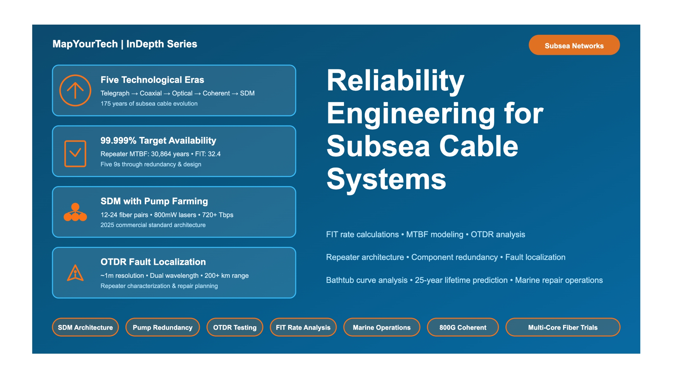

Reliability Engineering for Subsea Cable Systems
Submarine Communications | Network EngineeringIntroduction
Subsea cable systems form the critical backbone of global telecommunications, carrying more than 95% of international data traffic across the world's oceans. These remarkable engineering achievements connect continents, enable global commerce, and support the digital infrastructure that modern society depends upon. However, the reliability of these systems is not achieved by chance—it is the result of decades of rigorous engineering discipline, comprehensive quality assurance processes, and sophisticated reliability engineering practices.
Reliability engineering for subsea cable systems represents one of the most demanding applications of engineering reliability principles. Unlike terrestrial systems, subsea cables must operate continuously for 25 years in harsh ocean environments at depths reaching 8,000 meters, under pressures exceeding 1,000 atmospheres, without the possibility of routine maintenance. A single component failure can trigger costly repair operations requiring specialized cable ships, taking weeks to complete, and potentially disrupting critical international communications. The cost of repairs at sea can range from hundreds of thousands to millions of dollars, depending on location and complexity.
The importance of reliability engineering in subsea cable systems cannot be overstated. Modern systems are designed to achieve availability targets of 99.9% to 99.999% over their operational lifetime. This translates to acceptable downtime measured in minutes per year for tier-one systems. To meet these stringent requirements, reliability engineering pervades every aspect of system design, from component selection and redundancy architecture to manufacturing quality control and operational maintenance strategies.
Why Reliability Engineering Matters for Subsea Cables
Subsea cable systems face unique challenges that make reliability engineering critical. External aggression from fishing activities and ship anchors causes approximately 70% of all cable faults, predominantly in shallow water areas less than 1,000 meters deep. Component failures in repeaters, branching units, and power feeding equipment account for the remaining failures. With repair operations taking days to weeks and costing millions of dollars, the economic and operational imperative for high reliability is clear. A well-designed system with proper redundancy and quality assurance can achieve the target of fewer than one ship repair per 25-year lifetime due to component failures alone.
The Scope of Subsea Cable Reliability
Reliability engineering for subsea cable systems encompasses multiple interconnected domains. At the component level, it involves rigorous qualification testing, failure mode analysis, and statistical reliability modeling for every element from pump lasers to optical splices. At the system level, it requires careful power budget management, optical signal-to-noise ratio allocation, and redundancy architecture design. At the network level, it demands route engineering to minimize exposure to external hazards, strategic placement of branching units for network resilience, and maintenance planning for rapid fault response.
The reliability challenge is compounded by the scale and diversity of modern subsea cable networks. A typical transoceanic system may span 10,000 kilometers, contain 100-200 repeaters, support 8-16 fiber pairs per cable, and deliver aggregate capacity exceeding 100 terabits per second. Branch networks add complexity through optical add-drop multiplexing at branching units, power switching configurations, and multiple landing points. Each element must be engineered for high reliability while maintaining acceptable system cost and performance.
Figure 1: Modern Subsea Cable System Architecture
Historical Context and Evolution
The evolution of reliability engineering for subsea cable systems spans more than 170 years, beginning with the first transatlantic telegraph cables in the 1850s and continuing through today's multi-terabit optical systems. This historical perspective is essential for understanding current reliability practices, as many of today's methodologies emerged from hard-won lessons learned through operational failures and technological evolution.
Early Telegraph Era (1850-1960)
The first attempts at transatlantic cable communication in the 1850s were marked by spectacular failures that taught fundamental lessons about marine cable reliability. The 1858 telegraph cable operated for only three weeks before failing, primarily due to inadequate insulation and poor understanding of electrical stresses in the marine environment. These early failures drove the development of improved cable designs with better mechanical protection and electrical insulation.
By the late 19th century, the industry had established basic reliability principles including the use of gutta-percha insulation, steel wire armoring for mechanical protection, and careful cable laying procedures to minimize installation damage. However, reliability remained a significant challenge, with cable lifetimes often limited to 5-10 years due to material degradation, marine organism damage, and external mechanical stresses from fishing equipment and ship anchors.
The telegraph era established several reliability practices that remain relevant today. Route surveys became standard practice to avoid areas with high external hazard risk. Cable armoring was differentiated based on water depth, with heavier protection in shallow waters where fishing activity was prevalent. Maintenance agreements were formed to share the costs and resources needed for cable repair operations, establishing the framework for today's cable maintenance agreements.
Coaxial Cable Era (1956-1988)
The introduction of the first transatlantic telephone cable (TAT-1) in 1956 marked a technological revolution and brought new reliability challenges. Coaxial cable systems required electronic repeaters spaced approximately every 60 kilometers to regenerate signals. These vacuum tube-based repeaters introduced component failure modes that did not exist in passive telegraph cables. System designers faced the challenge of achieving acceptable reliability from hundreds of repeaters, each containing multiple vacuum tubes with limited operational lifetimes.
The coaxial cable era drove the development of formal reliability engineering methodologies. System designers adopted statistical approaches to predict cumulative failure rates from individual component reliabilities. Redundancy became a fundamental design principle, with critical components duplicated to improve overall system reliability. Manufacturing quality control processes were established to screen for early failures and ensure consistent component performance.
Operational experience with coaxial systems provided crucial data on external aggression patterns. Analysis showed that approximately 70% of cable faults resulted from fishing activities, predominantly in water depths less than 200 meters. This led to widespread adoption of cable burial as a protection strategy. The first commercial use of cable plowing equipment occurred in 1967 to retrofit existing systems, and burial became standard practice for new installations in shallow water.
The coaxial era also saw the establishment of regional Construction and Maintenance Agreements (CMAs) to pool resources for system repair. Major operators formed organizations to share cable ship capacity and maintenance expertise, establishing standing charge systems to ensure rapid response capability. This cooperative approach to maintenance remains a cornerstone of subsea cable operations today.
Optical Fiber Revolution (1988-2008)
The deployment of the first fiber optic transatlantic cable (TAT-8) in 1988 initiated the modern era of subsea cable communications. Optical fiber technology offered dramatically higher capacity (280 Mbps initially, versus 4,000 voice circuits for TAT-7 coaxial), lower signal loss (0.2 dB/km versus 6 dB/km), and fundamentally improved reliability compared to coaxial systems. The optical repeaters contained no active electronics, operating purely on optical amplification principles once EDFAs were introduced.
The introduction of erbium-doped fiber amplifiers (EDFAs) in the early 1990s represented the most significant reliability improvement in subsea cable history. EDFAs eliminated complex electronic regenerators that had plagued coaxial systems, replacing hundreds of electronic components per repeater with simple optical gain medium pumped by semiconductor lasers. This reduction in component count and electronic complexity improved inherent reliability by orders of magnitude while simultaneously reducing power consumption from several hundred watts to under 100 watts per repeater.
Dense wavelength division multiplexing (DWDM) emerged in the late 1990s as the primary capacity scaling mechanism. By transmitting multiple independent wavelength channels through a single fiber, DWDM systems increased capacity from single-wavelength 2.5 Gbps (STM-16) to 32-40 wavelengths carrying 10 Gbps each by the early 2000s. This era established reliability engineering practices still used today: redundant pump laser architectures, physics-of-failure modeling, accelerated aging protocols, and statistical lifetime prediction from accelerated testing data.
The pre-coherent era required careful dispersion management through alternating fiber types or dispersion compensation modules in repeaters. Modulation formats were limited to on-off keying (OOK) and differential phase shift keying (DPSK), with receiver sensitivity and chromatic dispersion tolerance setting fundamental limits on system reach and capacity. These constraints drove system-specific optimization where cable plant designs were matched to specific transmission equipment, creating "turnkey" systems supplied as integrated packages.
Coherent Optical Era (2008-2020)
The introduction of coherent detection with digital signal processing in 2008 revolutionized submarine cable systems as profoundly as the transition from coaxial to optical fiber. Coherent systems employ polarization-multiplexed quadrature amplitude modulation (PM-QAM) with sophisticated DSP algorithms in the receiver to compensate for transmission impairments electronically. This breakthrough enabled electronic compensation of chromatic dispersion, eliminating the need for dispersion compensation fiber or modules in the submarine plant.
The reliability implications of coherent technology were transformative. By moving dispersion compensation from the submarine plant to shore-based electronics, coherent systems simplified wet plant design substantially. Repeaters became simpler, containing only optical amplification and monitoring functions without dispersion compensating elements. The simplified architecture reduced component count, failure modes, and manufacturing complexity while improving overall system reliability. Additionally, the open cable architecture enabled wet plant and dry plant to be supplied by different vendors, fostering competition and innovation.
Coherent systems enabled capacity scaling through higher-order modulation formats (QPSK, 8-QAM, 16-QAM, 64-QAM) and spectral efficiency improvements. Channel rates increased from 10 Gbps to 40 Gbps to 100 Gbps through this period, with corresponding increases in sensitivity to optical noise and nonlinear effects. The reliability engineering challenge shifted toward managing tighter OSNR budgets and understanding how higher spectral density impacts long-term system margin. Physics-of-failure models were enhanced to predict performance degradation of complex DSP-enabled transponders over 25-year periods.
This era also saw the emergence of branching units with reconfigurable optical add-drop multiplexer (ROADM) capability, enabling dynamic wavelength routing without submarine intervention. While ROADMs added architectural flexibility for meshed network designs, they introduced new reliability considerations through wavelength-selective switches, power equalization systems, and remote reconfiguration capabilities. The industry developed qualification protocols specifically for submarine ROADM components to ensure they met the stringent 25-year reliability requirements despite increased complexity.
SDM & Hyperscale Era (2020-2025)
The period from 2020 to 2025 marks a fundamental paradigm shift in submarine cable design philosophy: optimizing total cable capacity rather than per-fiber capacity. Space division multiplexing (SDM) using increased fiber pair counts (12-24 pairs versus traditional 4-8 pairs) combined with pump farming technology enables this optimization. Pump farming decouples optical pump power from electrical power consumption per fiber pair by sharing pump lasers across multiple amplifier pairs, making higher fiber counts economically and technically viable.
SDM systems achieve reliability improvements through reduced stress per fiber pair. By distributing capacity across more fibers, each fiber operates at lower power levels and in less nonlinear regimes, improving margin and reducing aging stress on optical components. Modern repeaters contain 16-24 amplifier pairs pumped by shared laser arrays, with individual amplifier pair FIT rates around 7.6 compared to higher rates in earlier single-pair designs. The aggregate repeater reliability remains excellent despite increased component count because redundancy and pump sharing dramatically reduce effective failure rates.
The hyperscale content provider emergence as primary cable investors transformed the industry business model and reliability requirements. Companies operating global cloud platforms invested in or wholly owned 59+ international cables by 2024, compared to just 20 in 2017. These operators demand extremely high availability (Five 9s: 99.999%) to support their service level agreements, driving enhanced route diversity strategies, improved maintenance response protocols, and investment in predictive maintenance technologies using AI and machine learning.
Technology milestones achieved during this period include 400G coherent transponders entering commercial deployment (2021-2023), 800G systems in development (2024-2025), and multi-core fiber field trials beginning with the IOEMA project targeting 2027 service. Per-fiber capacity exceeded 30 Tbps on point-to-point links, while total cable capacity reached 720+ Tbps for 24-pair SDM systems. These advances required evolution of reliability engineering practices to address higher baud rates (140-200 Gbaud), advanced modulation formats (up to probabilistically-shaped 64-QAM), and novel fiber types with lower effective area (80-110 μm² versus traditional 125 μm²).
Future Directions and Emerging Challenges
The industry outlook for 2025-2030 centers on several key technology and policy developments. Multi-core fiber transitions from field trials to early commercial deployment, with 2-core and 4-core fibers offering nearly 10× density improvement over single-core SDM approaches. However, native multi-core amplification remains a significant technical challenge, with current systems using fan-in/fan-out devices and separate amplifiers per core. Reliability engineering for multi-core systems must address core crosstalk management, fan-in/fan-out device longevity, and the complexity of scaling pump power across numerous cores.
Security and resilience have become dominant concerns driving international policy coordination. The United Nations established the International Advisory Body for Submarine Cable Resilience in November 2024 under ITU coordination with ICPC partnership. This initiative reflects cables' elevation to critical infrastructure status and recognition that cable security requires coordinated international approaches. The European Commission issued recommendations on secure and resilient submarine cable infrastructures in 2024, establishing frameworks for enhanced protection against both physical and cyber threats.
The industry continues experiencing approximately 200 cable disruption incidents annually worldwide, with 70% caused by external aggression (fishing gear, anchors, geological events). Route diversity investment has intensified, with new systems avoiding high-risk areas and alternative routing becoming standard practice for critical connectivity. Advanced cable burial techniques, real-time monitoring systems, and improved coordination with fishing communities and marine industries aim to reduce the external aggression fault rate that has remained stubbornly persistent despite decades of protection efforts.
Artificial intelligence and machine learning applications to cable operations represent a nascent but potentially transformative development. AI-driven predictive maintenance systems analyze vast telemetry datasets to identify subtle precursors of component degradation, potentially enabling proactive component replacement before failures occur. Network optimization algorithms using machine learning can dynamically adjust operating parameters to maximize margin and extend component lifetimes. However, these technologies remain in early deployment, with reliability engineering methodologies still evolving to incorporate AI/ML capabilities into formal assurance processes.
Figure 2: Evolution of Subsea Cable Reliability Engineering (5 Distinct Eras)
Fundamental Concepts and Principles
Reliability engineering for subsea cable systems rests on a foundation of well-established theoretical principles combined with practical engineering methodologies developed through decades of operational experience. This section examines the core concepts that guide reliability analysis, design, and assurance throughout the system lifecycle.
Reliability Metrics and Definitions
Understanding reliability requires precise definitions of key metrics used to quantify and predict system performance. The most fundamental metric is the failure rate, typically expressed as FIT (Failures In Time), defined as the number of failures expected in one billion device-hours of operation. For a component with a failure rate of 100 FIT, the probability of failure during a 25-year operational period can be calculated using exponential probability distributions.
Read the Full Analysis with Premium
The remaining 89% of this article — the design numbers, trade-offs and field guidance — is part of MapYourTech Premium, along with the full premium library, courses and professional tools.


