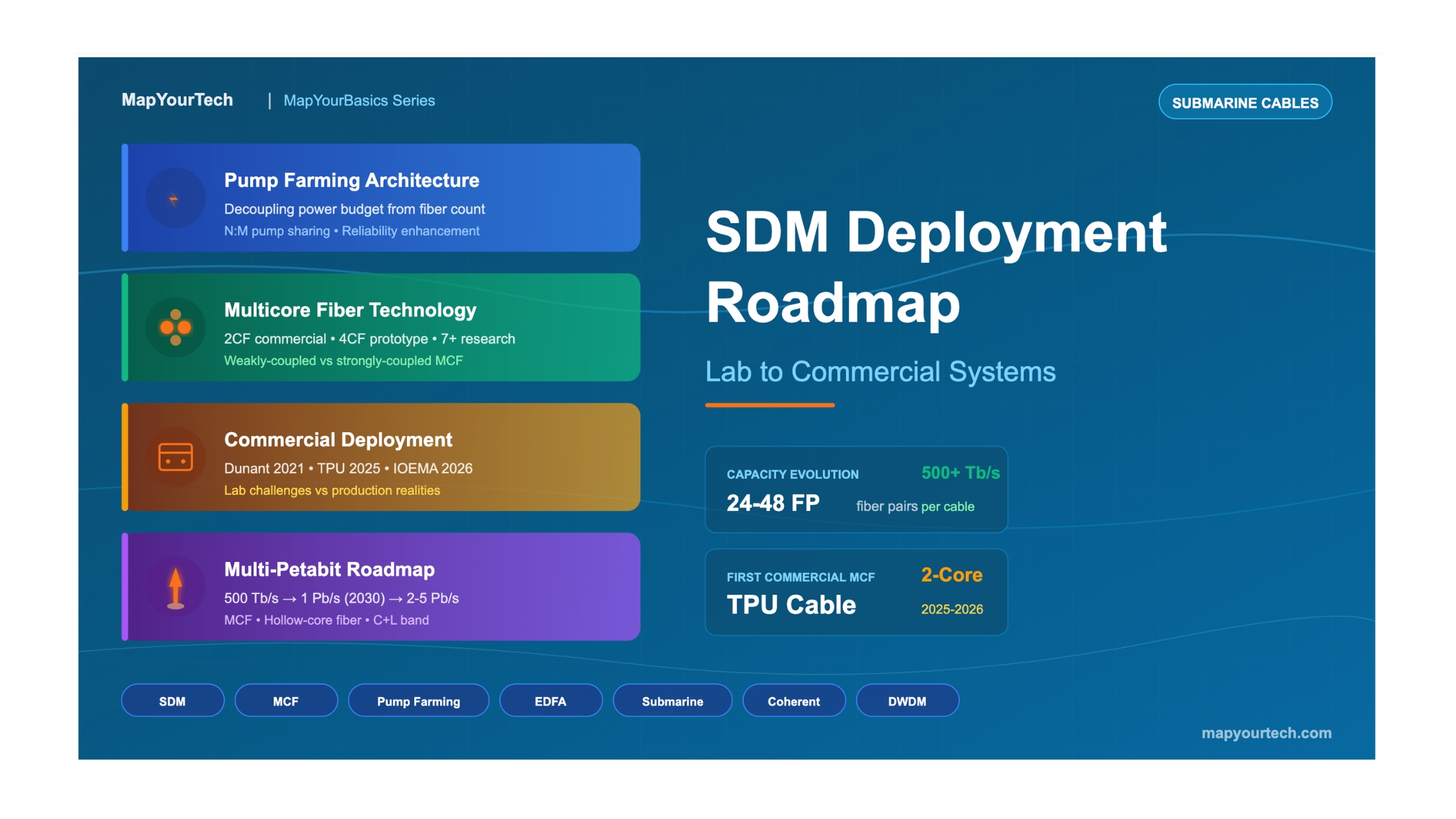

SDM Deployment Roadmap: From Lab to Commercial Systems
Advanced Deep Dive into Space Division Multiplexing Technology Evolution, Commercial Implementation Challenges, and Future Directions for Multi-Petabit Submarine Networks
Introduction
Space Division Multiplexing (SDM) represents a fundamental change of approach in submarine optical communication systems, where the optimization objective shifts from maximizing capacity per individual fiber pair to optimizing total cable capacity under cost and powering constraints. This technology addresses the approaching Shannon limit of conventional single-mode fibers by exploiting the spatial dimension through parallel transmission paths, including higher fiber pair counts, multicore fibers (MCF), and potentially few-mode fibers (FMF) in future implementations.
The transition from laboratory demonstrations to commercial deployments has accelerated significantly since 2018, when SDM technologies began appearing in production submarine cable systems. The Taiwan-Philippines-US (TPU) cable system, planned for ready-for-service in 2025-2026, represents the first commercial deployment of two-core multicore fiber technology, marking a watershed moment in the industry's adoption of advanced SDM approaches beyond simple fiber count increases.
The development roadmap for SDM encompasses multiple technological tracks operating in parallel: increasing fiber pair counts within existing cable structures, deploying reduced-diameter fibers (200 μm coating), implementing weakly-coupled multicore fibers, and researching strongly-coupled MCF with MIMO equalization. Each approach presents distinct trade-offs between capacity gains, system complexity, and economic viability that must be carefully evaluated in the context of specific deployment scenarios.
Advanced Concepts and Theoretical Framework
2.1 SDM Paradigm Shift: From Fiber-Centric to Cable-Centric Optimization
The fundamental principle underlying SDM in submarine systems represents a change of approach from traditional system design. Conventional approaches focused on maximizing spectral efficiency and capacity per individual fiber pair, employing large effective area fibers (Aeff ≥ 150 μm²), high-power amplifiers operating near the nonlinear threshold, and sophisticated modulation formats. The SDM approach instead optimizes total cable capacity under strict powering constraints, treating fiber count as a variable parameter rather than a fixed constraint.
This optimization leverages a fundamental property of Shannon's capacity formula: while capacity scales logarithmically with SNR (and thus with optical power per fiber), it scales linearly with the number of parallel spatial channels. Mathematically, for a cable with NFP fiber pairs, the total capacity can be expressed as:
SDM Cable Capacity Optimization
The achievable cable capacity under SDM optimization:
Ccable = NFP × 2polars × χ × BEDFA × log₂(1 + SNRTOT/pen)

Where:
  NFP = Number of fiber pairs
  χ = Spectral occupancy (symbol rate/channel spacing)
  BEDFA = Amplifier bandwidth (~4.5 THz for C-band)
  SNRTOT = End-to-end electrical SNR
  pen = System penalty / gap to Shannon (>1 in linear)

Key insight: Capacity scales linearly with NFP but only
logarithmically with SNR (proportional to power per fiber)
The practical consequence is that doubling the fiber count while halving the power per fiber results in a net capacity increase, despite reduced per-fiber performance. This trade-off becomes particularly favorable under power-constrained conditions typical of transoceanic submarine systems, where the total electrical power available for repeaters is fundamentally limited by cable feeding equipment (PFE) voltage constraints and cable conductor resistance.
2.2 Pump Sharing/Farming: The Enabling Technology
The pump sharing (or pump farming) technique represents the critical enabler for practical SDM implementation in submarine systems. This architecture decouples the electrical power available for a repeater from the optical pump power delivered to individual EDFAs. In conventional repeater designs, each fiber pair has dedicated pump lasers, creating a direct relationship between fiber count and electrical power consumption. Pump sharing breaks this constraint by pooling multiple 980 nm pump laser outputs and redistributing them across a variable number of amplifiers.
The pump sharing mechanism operates by combining outputs from n optical pumps and distributing the combined power to m EDFAs, where the ratio n:m can be optimized based on system requirements. For example, a configuration of 4 pumps shared among 8 fiber pairs (4P:8FP) delivers half the pump power per EDFA compared to a dedicated 2P:2FP arrangement, but enables twice the spatial parallelism within the same electrical power envelope. The resulting reduction in per-fiber SNR is more than compensated by the doubling of transmission paths.
Pump Sharing Power Distribution
Pp,amp(NFP) = ηmux × Ppump,rep / (2 × NFP)

Where:
  Pp,amp = Optical pump power per amplifier
  ηmux = Pump combining/multiplexing efficiency (<1)
  Ppump,rep = Total pump power budget per repeater
  NFP = Number of fiber pairs

Impact on EDFA output power:
  Pout,amp ∝ Pp,amp (above transparency threshold)

SNR scaling with pump sharing:
  SNRASE(NFP) ∝ Pout,amp / (Nrep × NF × G)
                     ∝ 1/NFP (at fixed total pump budget)
A critical benefit of pump sharing extends beyond power efficiency to system reliability. In traditional architectures, a single pump failure directly impacts one fiber pair. With pump sharing, each EDFA receives contributions from multiple pump sources, so individual pump failures cause only marginal output power reduction rather than complete fiber pair loss. This enhanced fault tolerance aligns with the stringent 25-year operational lifetime requirements of submarine systems.
2.3 Multicore Fiber Technologies
Multicore fibers (MCFs) represent the next evolutionary step beyond simple fiber count increases, offering enhanced spatial density by embedding multiple transmission cores within a single fiber cladding. The technology branches into two distinct categories with fundamentally different operational characteristics: weakly-coupled (uncoupled) MCFs and strongly-coupled MCFs.
2.3.1 Weakly-Coupled Multicore Fibers
Weakly-coupled MCFs are designed to minimize inter-core crosstalk to levels where signals can be processed independently without MIMO equalization. Current designs support 2-4 cores within a standard 125 μm cladding diameter, with crosstalk suppressed below approximately -30 dB/100 km to avoid significant multipath interference (MPI) penalties. The primary advantage is full compatibility with existing single-core transceiver equipment; each core operates as an independent transmission channel.
Two-core fiber (2CF) has emerged as the most commercially mature MCF variant, with the Taiwan-Philippines-US (TPU) cable system scheduled to deploy 2CF technology on its Taiwan and Philippines branches, marking the first commercial MCF deployment in submarine systems. The 2CF design enables bidirectional transmission (one core per direction), which effectively eliminates crosstalk concerns while doubling fiber density. Recent advances have achieved attenuation below 0.145 dB/km for 2CF, approaching single-core fiber performance.
2.3.2 Strongly-Coupled MCFs and MIMO Processing
Strongly-coupled MCFs allow significant inter-core signal coupling, requiring multiple-input multiple-output (MIMO) digital signal processing at receivers to separate and recover transmitted signals. While this adds complexity, research has demonstrated that strong coupling causes rapid signal decorrelation among cores, effectively reducing nonlinear impairments—analogous to an enlarged effective area. This property could enable transmission at higher power levels per core, partially offsetting the MIMO processing overhead.
However, the current industry trajectory for coherent transponders emphasizes reduced complexity, cost, and power consumption. Integrating MIMO for SDM runs counter to this direction, and the computational requirements scale with O(N²) where N is the number of coupled modes, making strongly-coupled systems more suitable for specialized applications or future generations where processing efficiency improves substantially.
System Architecture and Design Considerations
3.1 Cable Structure Evolution for SDM
Accommodating higher fiber counts within submarine cables while maintaining the established 17 mm outer diameter of Light Weight (LW) cable represents a significant engineering challenge. The traditional cable structure allocates approximately 3 mm for the fiber tube, sufficient for 8-12 fiber pairs with standard 250 μm coating diameter fibers. SDM requirements of 24+ fiber pairs necessitate either cable redesign or fiber dimension reduction.
The industry has pursued parallel approaches to this challenge. First, the tube diameter has been increased to approximately 5 mm by redesigning the cable structure—specifically, increasing the number of strands in the inner strength member to maintain the vault effect while accommodating the larger tube. Second, reduced coating diameter fibers (200 μm versus traditional 250 μm) have been qualified for submarine applications, theoretically enabling 1.6× spatial density improvement. Third, multicore fibers offer further density increases without cable redesign: a 24-fiber-pair cable using 2-core MCF provides equivalent capacity to a 48-fiber-pair single-core design.
3.2 Repeater Architecture for SDM
The evolution of repeater design for SDM systems involves increasingly sophisticated pump sharing architectures and, eventually, the integration of multicore amplification. Current production repeaters support 24 fiber pairs using single-core EDFAs with pump sharing ratios typically configured as 4 pumps per 4-8 fiber pairs. The repeater housing dimensions have remained largely unchanged to maintain compatibility with existing deployment and recovery equipment, placing significant constraints on component density.
For systems beyond 24 fiber pairs using 4-core MCF (equivalent to 96 cores per cable), housing all required single-core EDFAs becomes physically impractical. Two architectural paths are under consideration: staggered repeaters (splitting amplification across two housings at half-span intervals) and integrated multicore EDFAs. The staggered approach doubles deployment complexity and repeater count, while MC-EDFAs require significant development of cladding-pumped erbium-doped multicore fibers and associated integration technologies.
Engineering Trade-off: FIFO Device Integration
Fan-in/fan-out (FIFO) devices are required to interface multicore fibers with single-core amplifiers. Current FIFO technology introduces approximately 0.3-0.5 dB insertion loss per device, requiring two devices per span (at each repeater). For a 70 km span, this translates to equivalent fiber attenuation increase from 0.158 dB/km to 0.167 dB/km—necessitating approximately 4% more repeaters to maintain system performance, offsetting some MCF capacity benefits.
Implementation Complexity and Commercial Deployment
4.1 Commercial SDM Deployment Timeline
The commercialization of SDM technology has progressed through distinct phases, beginning with high-fiber-count systems using conventional single-core fibers and advancing toward multicore implementations. The deployment chronology reflects both technological maturation and market demand evolution.
SubCom and ASN introduce pump sharing architectures enabling 12-16 fiber pair systems. Google's Dunant cable enters construction as first 12FP SDM deployment.
Google's Dunant transatlantic cable achieves ready-for-service with 12 fiber pairs delivering 250 Tb/s capacity—first commercial SDM submarine system.
Multiple vendors qualify 24 fiber pair cable systems. PLCN deploys C+L band amplification (6FP × 2 bands = 12 equivalent FPs). 2CF fiber qualification completed for submarine applications.
TPU (Taiwan-Philippines-US) cable system deploys 2-core MCF on regional branches—first commercial multicore fiber submarine deployment. Cable manufacturers qualify 18-20 kV wet plant.
IOEMA project (1,371 km) planned with 24 pairs of 2-core fiber providing 48 equivalent fiber pairs. Industry roadmaps show 32FP single-core systems entering qualification.
Industry roadmaps project 48FP single-core and 4-core MCF systems. Multi-petabit transoceanic cables anticipated to meet AI-driven bandwidth demands.
4.2 Technical Challenges in Commercial Deployment
Translating laboratory SDM demonstrations to production submarine systems involves addressing numerous practical challenges that laboratory experiments can bypass or ignore. These challenges span fiber manufacturing, component integration, system commissioning, and long-term operational considerations.
| Challenge Area | Laboratory Context | Commercial Reality | Mitigation Approach |
|---|---|---|---|
| Fiber Attenuation | Short spans, controlled samples | Production consistency over 1000s km, cabling stress | Process optimization, 200 μm fiber qualification |
| MCF Crosstalk | Optimized fiber samples | Variation across production lots, splice contributions | Bidirectional transmission, heterogeneous core designs |
| FIFO Devices | Lab-grade, individually optimized | Volume production, 0.3-0.5 dB insertion loss | Fusion-spliced integration, loss budget allocation |
| Repeater Integration | Accessible, serviceable configurations | 25-year maintenance-free operation, space constraints | Pump sharing, component miniaturization |
| Power Budget | Unconstrained power supply | PFE voltage limits (18-20 kV), cable resistance | Higher voltage PFE development, optimized line current |
| Commissioning Time | Unlimited characterization | Multiple days for complete cable GSNR mapping | Selective GSNR measurement strategy |
Power Limitation: The Fundamental Constraint
Technical studies have concluded that advancing MCF or hollow-core fiber technologies without first addressing power limitations may prove counterproductive. The maximum achievable capacity scales proportionally to available repeater pump power, and multi-petabit cables will definitively require new solutions to increase cable powering capability, particularly for transoceanic distances exceeding 6,000 km.
Performance Analysis and Optimization
5.1 Capacity-Distance Trade-offs
SDM system optimization involves complex multi-dimensional trade-offs between fiber count, per-fiber SNR, repeater spacing, and total cable capacity. The fundamental relationship emerges from the interplay between parallel capacity gains and the power-dependent SNR reduction as pump power is distributed across more amplifiers.
Analysis reveals that capacity gains from increased parallelism exceed 4× at constant total optical power budget when fiber count increases by 8-10× in high-SNR regimes. However, these gains diminish as systems approach practical constraints. Once optimum SNR regions are achieved, classical system parameters regain paramount importance: available pump power, EDFA optical efficiency, noise figure, and fiber attenuation.
SDM Capacity Scaling Laws
Maximum achievable capacity under power constraints:

Cmax ∝ (ηOO × ηmux) / (NF) × Ppump,total / (Ltot² × α²)

Key scaling relationships:

1. Cmax ∝ Ppump,total
   Linear with available pump power budget

2. Cmax ∝ ηOO / NF
   Optical efficiency / noise figure ratio critical
   3 dB efficiency gain + 3 dB NF degradation = null net impact

3. Cmax ∝ 1 / α²
   Inverse square of fiber attenuation
   0.15 → 0.13 dB/km yields +33% capacity
   0.15 → 0.10 dB/km yields +125% capacity

4. Lrep,opt = 2/α
   Optimal repeater spacing under SDM optimization
   Typically 70-80 km for current fiber types
5.2 Comparative System Design Analysis
The following analysis compares three representative line designs for a 9,000 km point-to-point transoceanic link under identical powering constraints, illustrating the progression from high-spectral-efficiency to SDM-optimized approaches.
| Parameter | High Spectral Efficiency | SDM Design I (SCF) | SDM Design II (MCF) |
|---|---|---|---|
| Repeater Span | 73 km | 80 km | 90 km |
| Pump Sharing Index | 4P : 2FP | 4P : 4FP | 4P : 8FP |
| Repeater Output Power | 19.0 dBm | 18.0 dBm | 14.6 dBm |
| Fiber Effective Area | 150 μm² | 110 μm² | 80 μm² |
| GSNR | 11.7 dB | 10.8 dB | 7.4 dB |
| Core-Pairs | 14 | 24 | 48 |
| Core-Pair Capacity | 23.1 Tb/s | 20.1 Tb/s | 13.8 Tb/s |
| Total Cable Capacity | 323 Tb/s | 482 Tb/s | 660 Tb/s |
| PFE Voltage Used | 17.7 kV | 17.7 kV | 17.7 kV |
The comparison demonstrates that SDM optimization can double total cable capacity (+49% from Design I to II using identical voltage) by accepting reduced per-fiber performance. The transition from 150 μm² to 80 μm² effective area fibers reduces per-fiber cost while the capacity reduction is offset by increased parallelism. Notably, the lower-cost 80 μm² fibers prove economically advantageous in SDM configurations despite lower individual fiber performance.
Future Directions and Technology Roadmap
6.1 Path to Multi-Petabit Cable Systems
Industry forecasts anticipate requirement for 1 Pb/s transatlantic cable systems by 2030 and multi-petabit systems within the following decade, driven primarily by artificial intelligence workloads and data center interconnection demands. Achieving these capacity targets requires advancement across multiple technology fronts operating in parallel.
6.2 MCF vs Hollow-Core Fiber: Competing Visions
Two distinct technology paths compete as candidates for next-generation capacity increases beyond current SDM implementations: advanced multicore fibers and hollow-core fibers (HCF). Each offers unique advantages and faces different challenges on the path to commercialization.
Multicore fibers can increase capacity by a factor of 2-4× with weakly-coupled designs, potentially reaching 7× or higher with strongly-coupled variants requiring MIMO processing. The technology builds on established silica fiber manufacturing expertise and has already achieved commercial deployment with 2-core fiber. However, scaling beyond 4 cores within standard cladding requires either MIMO processing (adding transponder complexity) or larger cladding diameters (requiring cable redesign).
Hollow-core fibers offer an orthogonal advantage: light propagates through air rather than silica, dramatically reducing nonlinear effects and enabling transmission at much higher power levels (>30 dBm demonstrated without significant nonlinear penalty). This effectively increases the nonlinear threshold by orders of magnitude, allowing operation at higher SNR per fiber. Recent research has achieved HCF attenuation of approximately 0.11 dB/km at 1,550 nm, approaching viability for submarine applications. Additionally, HCF naturally supports extended wavelength bands (S+C+L and beyond) without the Raman-induced inter-band energy transfer that plagues solid-core multiband systems.
Critically, MCF and HCF are not mutually exclusive technologies and could be combined in future systems to multiply capacity gains. Technical-economic analysis suggests that the adoption timeline for both technologies depends heavily on resolving power limitations first—advancing spatial or spectral parallelism without addressing power constraints may prove counterproductive.
References
- ITU-T Recommendation G.654.E – Characteristics of a cut-off shifted single-mode optical fibre and cable, 2020.
- ITU-T Technical Paper – Optical fibre, cable and components for space-division multiplexing (SDM) transmission, 2023.
- Bolshtyansky, M.A., et al., "Single-mode fiber SDM submarine systems," Journal of Lightwave Technology, vol. 38, no. 6, pp. 1296-1304, 2020.
- Hasegawa, T., "Ultra-low loss 2-core fibre for expanding submarine cable capacity," IET Optoelectronics, 2024.
- Downie, J.D., et al., "On conditions influencing widespread deployment and commercialisation of space division multiplexing optical fibres in submarine cable systems," IET Optoelectronics, 2025.
- Meseguer, A.C., et al., "Multi-core vs hollow-core fibers: technical study of their viability in SDM power-constrained submarine systems," Journal of Lightwave Technology, vol. 41, no. 12, pp. 4002-4009, 2023.
- Srinivas, H., et al., "Modeling and experimental measurement of power efficiency for power-limited SDM submarine transmission systems," Journal of Lightwave Technology, vol. 39, no. 8, pp. 2376-2386, 2021.
- Google Cloud Blog, "Boosting Subsea Cables with Multi-Core Fiber Technology," September 2023.
- Pecci, P., et al., "Pump farming as enabling factor to increase subsea cable capacity," Proc. SubOptic 2019, New Orleans, USA.
- Sanjay Yadav, "Optical Network Communications: An Engineer's Perspective" – Bridge the Gap Between Theory and Practice in Optical Networking.
For educational purposes in optical networking and DWDM systems
Note: This guide is based on industry standards, best practices, and real-world implementation experiences. Specific implementations may vary based on equipment vendors, network topology, and regulatory requirements. Always consult with qualified network engineers and follow vendor documentation for actual deployments.

Optical Communications & Network Automation Expert | Author of 3 Books for Optical Engineers | Founder, MapYourTech
Optical networking engineer with nearly two decades of experience across DWDM, OTN, coherent optics, submarine systems, and cloud infrastructure. Founder of MapYourTech. Read full bio →
Follow on LinkedIn