The Bit Error Rate (BER) of a digital optical receiver indicates the probability of an incorrect bit identification. In other words, the BER is the ratio of bits received in error to the total number of bits received. Below lists different values for BER and their corresponding errors per bits and over time.
As we know that, the photocurrent is converted to a voltage then measured. The measurement procedure involves a decision as to whether the bit received is a 1 or a 0. The BER is a not only a function of the noise in the receiver and distortion in the system, but also on the decision level voltage,VD that is the threshold level above which the signal is classified as a 1 and below which the signal is classified as a 0. Even an ideal signal with no noise nor distortions has a non-zero BER if the decision level is set too high or too low. For example, if VD is set above the voltage of the 1 bit, the BER is 0.5, assuming equal probability of receiving a one and a zero.
|
BER |
Error per 10E-15 bits |
@ 10Gbps, One error in |
|
1×10⁻⁶ |
10,00,00,000 |
0.1 msec |
|
1×10⁻⁹ |
1,00,000 |
0.1 sec |
|
1×10-12 |
100 |
1.7 min |
|
1×10-15 |
1 |
1.2 days |
Mathematically, the Bit Error Rate is expressed as
BER = p(1)P(0 ⁄ 1) + p(0)P(1 ⁄ 0)
where p(1) and p(0) are the probabilities of receiving a 1 and a 0, respectively. P(0/1) is the probability of deciding a 0 when the bit is actually a 1, and P(1/0) is the probability of deciding a 1 when the bit is a 0.
The mathematical relations to BER for non-FEC operation when the threshold is set to the optimum value are:
where:
A commonly used approximation for this function is:
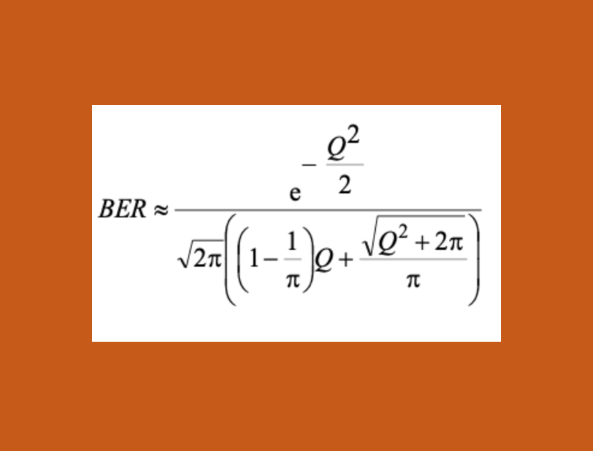
An alternative expression that gives accurate answers over the whole range of Q is expressed as:
Minimum BER as a function of Q where both formulas are compared.
BER to Q relation
e.g: BER of 10–12, is Q » 7.03.
Unlock Premium Content
Join over 400K+ optical network professionals worldwide. Access premium courses, advanced engineering tools, and exclusive industry insights.
Already have an account? Log in here


