
Based on my experience ,I have seen that Optical Engineers need to estimate Optical Signal-to-Noise Ratio (OSNR) often specially when they are dealing with network planning and operations .Mostly engineers use spreadsheet to perform these calculation or use available planning tool .This handy tool provides a method for user to quickly estimate the OSNR for a link and ensures flexibility to simulate by modifying power levels,Tx OSNR, number of channels . In this blog post, I will walk you through the features and functionalities of the tool, helping you understand how to use it effectively for your projects.For simplicity ,we have not considered Non-Linear penalties which user is requested to add as needed .
What is OSNR?
Optical Signal-to-Noise Ratio (OSNR) is a critical parameter in optical communication systems. It measures the ratio of signal power to the noise power in an optical channel. Higher OSNR values indicate better signal quality and, consequently, better performance of the communication system.
Features of the OSNR Simulation Tool
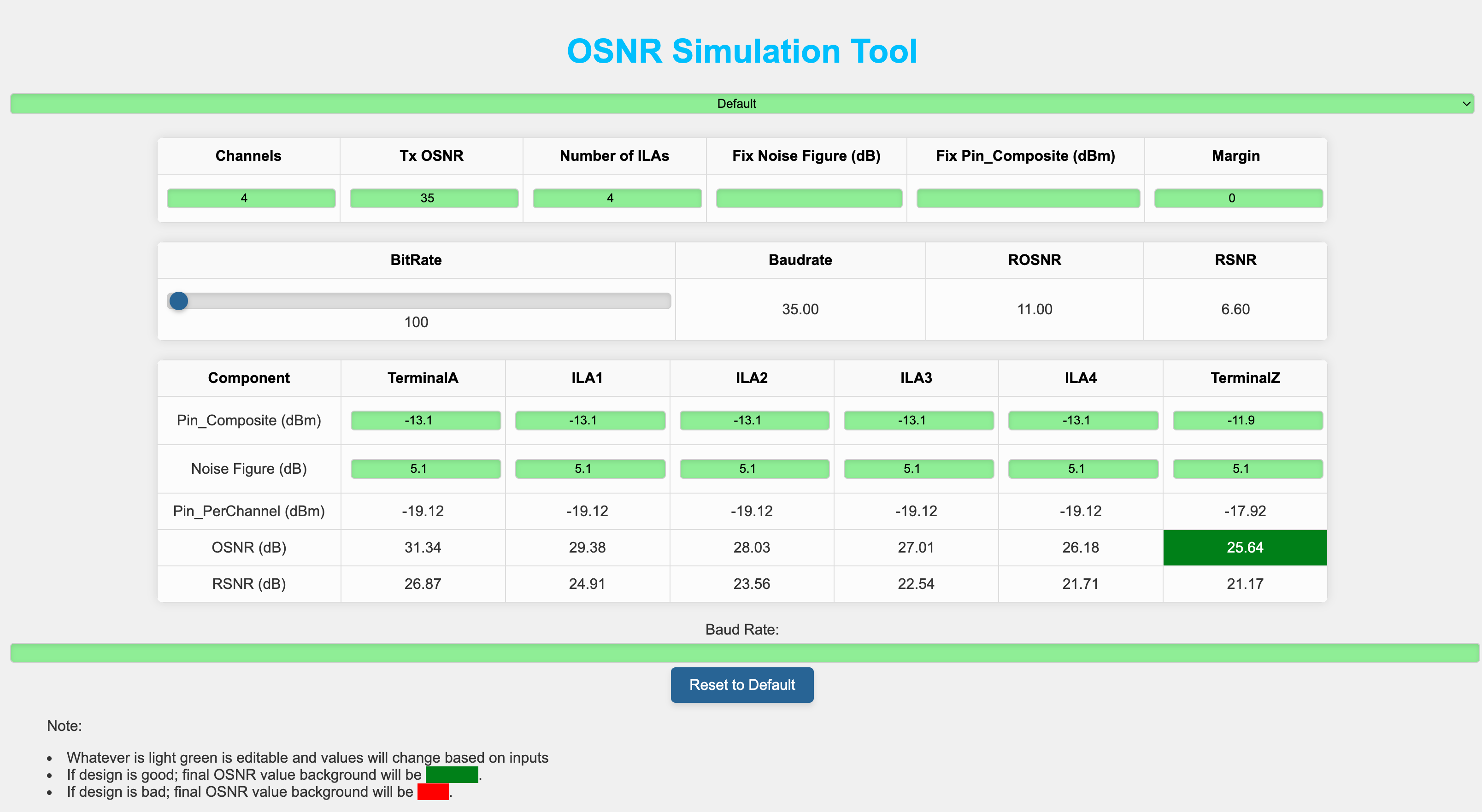
This OSNR Calculation Tool is designed to simplify the process of calculating the OSNR across multiple channels and Intermediate Line Amplifiers (ILAs). Here’s what the tool offers:
-
Input Fields for Channels, Tx OSNR, and Number of ILAs:
-
-
-
-
-
- Channels: The number of optical channels in the network. Adjust to simulate different network setups.
- Tx OSNR: The initial OSNR value at the transmitter.
- Number of ILAs: The number of in-line amplifiers (ILAs) in the network. Adjust to add or remove amplifiers.
- Set Noise Figure (dB) for all ILAs: Set a common noise figure for all ILAs.
- Margin: The margin value used for determining if the final OSNR is acceptable.
- Set Pin_Composite (dBm) for all: Set a common Pin_Composite (dBm) value for all components.
- BitRate: Controlled via a slider. Adjust the slider to select the desired bit rate.
- BaudRate: Automatically updated based on the selected bit rate.
- ROSNR: Automatically updated based on the selected bit rate.
- RSNR: Automatically updated based on the selected bit rate.
- Baud Rate: Additional input for manual baud rate entry.
-
-
-
-
-
-
Dynamic ILA Table Generation:
-
-
-
-
-
- The tool generates a table based on the number of ILAs specified. This table includes fields for each component (TerminalA, ILAs, TerminalZ) with editable input fields for Pin_Composite (dBm) and Noise Figure (dB).
-
-
-
-
-
-
Calculations and Outputs:
-
-
-
-
-
- Composite Power: The composite power calculated based on the number of channels and per-channel power.
- Net Power Change: The net power change when channels are added or removed.
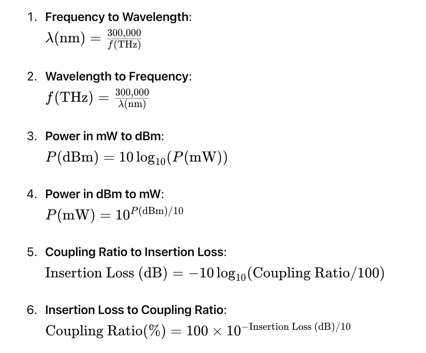
- Optical Parameter Conversions:
- Frequency to Wavelength and vice versa.
- Power in mW to dBm and vice versa.
- Coupling Ratio to Insertion Loss and vice versa.
- OSNR (dB): Displays the OSNR value for each component in the network.
- RSNR (dB): Displays the RSNR value for each component in the network.
-
-
-
-
-
-
Baud Rate and Required SNR Calculation:
-
-
-
-
-
- Input the Baud Rate to calculate the required Signal-to-Noise Ratio (SNR) for your system.SNR is related to Q-factor .
-
-
-
-
-
-
Reset to Default:
-
-
-
-
-
- A button to reset all fields to their default values for a fresh start.
-
-
-
-
-
Steps to Use the Tool
- Set the Initial Parameters:
-
-
-
-
- Enter the number of channels.
- Enter the Tx OSNR value.
- Enter the number of ILAs.
- Optionally, set a common Noise Figure for all ILAs.
- Enter the margin value.
- Optionally, set a common Pin_Composite (dBm) for all components.
-
-
-
-
- Adjust Bit Rate:
-
-
-
-
- Use the slider to select the desired bit rate. The BaudRate, ROSNR, and RSNR will update automatically.
-
-
-
-
- Calculate:
-
-
-
-
- The tool will automatically calculate and display the OSNR and RSNR values for each component.
-
-
-
-
- Review Outputs:
-
-
-
-
- Check the Composite Power, Net Power Change, and Optical Parameter Conversions.
- Review the OSNR and RSNR values.
- The final OSNR value will be highlighted in green if it meets the design criteria (OSNR >= ROSNR + Margin), otherwise, it will be highlighted in red.
-
-
-
-
- Visualize:
-
-
-
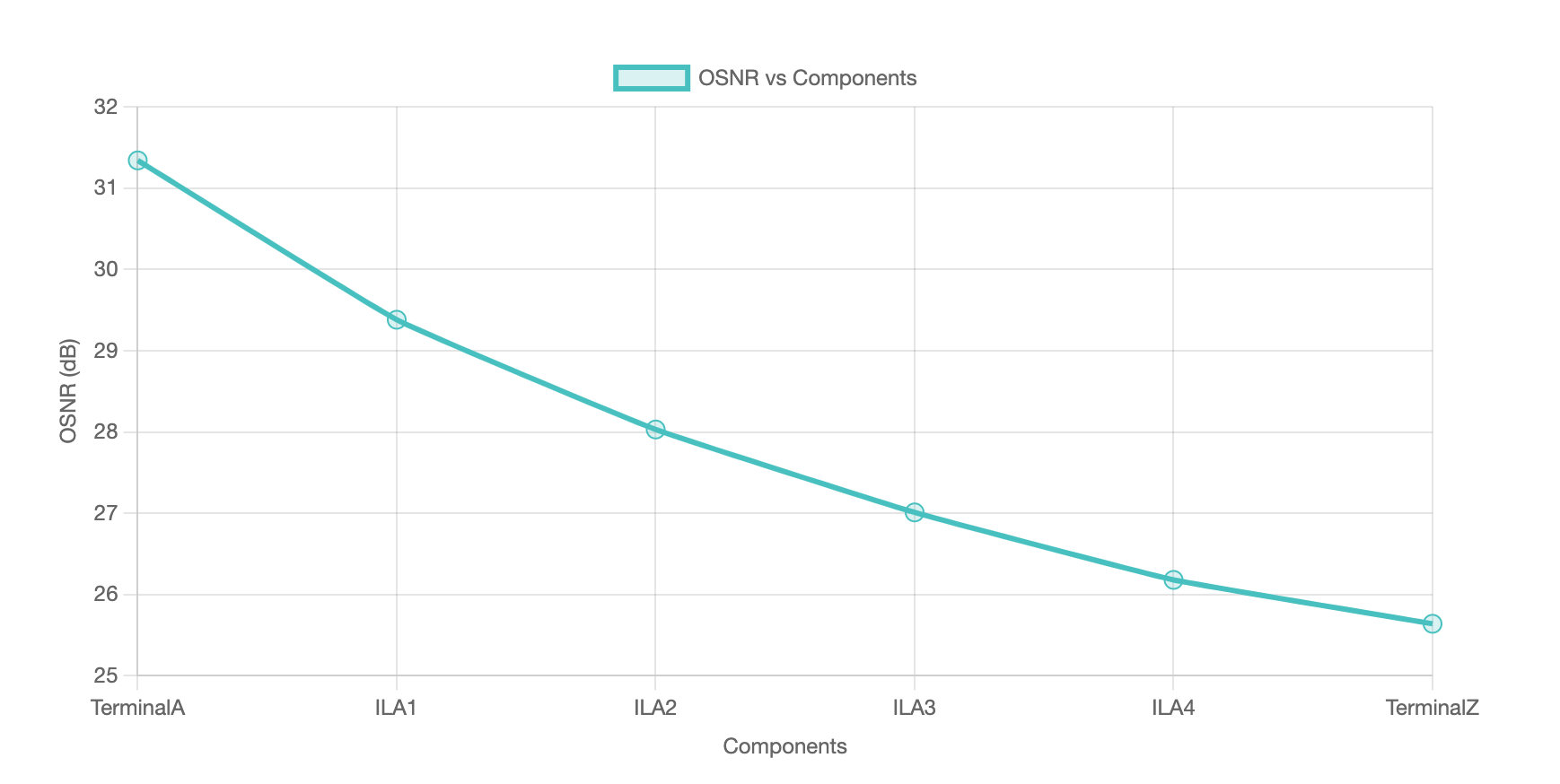
- The OSNR vs Components chart will provide a visual representation of the OSNR values across the network components.
-
-
-
- Reset to Default:
-
-
-
-
- Use the “Reset to Default” button to reset all values to their default settings.
-
-
-
-
Themes
You can change the visual theme of the tool using the theme selector dropdown. Available themes include:
-
-
-
-
- Default
- Theme 1
- Theme 2
- Theme 3
- Theme 4
-
-
-
Each theme will update the colors and styles of the tool to suit your preferences.
Notes:
- Editable fields are highlighted in light green. Adjust these values as needed.
- The final OSNR value’s background color will indicate if the design is acceptable:
- Green: OSNR meets or exceeds the required margin.
- Red: OSNR does not meet the required margin.
Formulas used:
Composite Power Calculation
Composite Power (dBm)=Per Channel Power (dBm)+10log10(Total number of channels − Insertion Loss of Filter (dB)
Net Power Change Calculation
Net Power Change (dBm)=10log10(Channels added/removed+Channels undisturbed)−10log10(Channels undisturbed)
Optical Parameter Conversions
OSNR Calculation

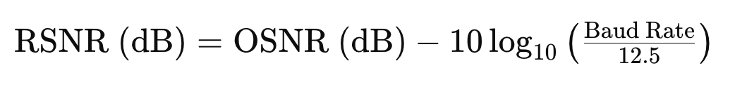
RSNR Calculation
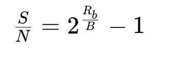
Shannon Capacity Formula
To calculate the required SNR given bit rate and baud rate:
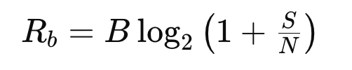
Rearranged to solve for SNR:
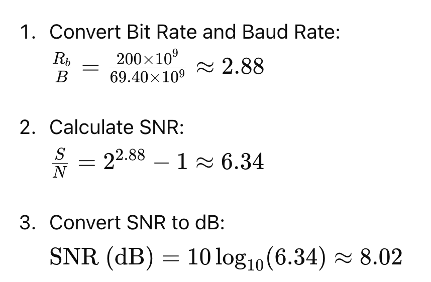
Example Calculation
Given Data:
- Bit Rate (Rb): 200 Gbps
- Baud Rate (Bd): 69.40 Gbaud
Example Tool Usage
Suppose you are working on a project with the following specifications:
-
-
-
-
-
- Channels: 4
- Tx OSNR: 35 dB
- Number of ILAs: 4
-
-
-
-
- Enter these values in the input fields. (whatever is green is editable)
- The tool will generate a table with columns for TerminalA, ILA1, ILA2, ILA3, ILA4, and TerminalZ.
- Adjust the Pin_Composite (dBm) and Noise Figure (dB) values if necessary.
- The tool calculates the Pin_PerChannel (dBm) and OSNR for each component, displaying the final OSNR at TerminalZ.
- Input the Baud Rate to calculate the required SNR
- User can see the OSNR variation at each component level(ILA here) to see the variation.