Channel Coding-A walkthrough
This article is just for revising Channel Coding concepts.
Channel coding is the process that transforms binary data bits into signal elements that can cross the transmission medium. In the simplest case, in a metallic wire a bi- nary 0 is represented by a lower voltage, and a binary 1 by a higher voltage. How- ever, before selecting a coding scheme it is necessary to identify some of the strengths and weaknesses of line codes:
- High-frequency components are not desirable because they require more chan- nel bandwidth, suffer more attenuation, and generate crosstalk in electrical links.
- Direct current (dc) components should be avoided because they require physi- cal coupling of transmission elements. Since the earth/ground potential usually varies between remote communication ends, dc provokes unwanted earth-re- turn loops.
- The use of alternating current (ac) signals permits a desirable physical isola- tion using condensers and transformers.
- Timing control permits the receiver to correctly identify each bit in the trans- mitted message. In synchronous transmission, the timing is referenced to the transmitter clock, which can be sent as a separate clock signal, or embedded into the line code. If the second option is used, then the receiver can extract its clock from the incoming data stream thereby avoiding the installation of an additional line.
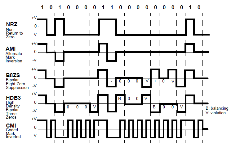
Figure 1.1: Line encoding technologies. AMI and HDB3 are usual in electrical signals, while CMI is often used in optical signals.
In order to meet these requirements, line coding is needed before the signal is trans- mitted, along with the corresponding decoding process at the receiving end. There are a number of different line codes that apply to digital transmission, the most widely used ones are alternate mark inversion (AMI), high-density bipolar three ze- ros (HDB3), and coded mark inverted (CMI).
Nonreturn to zero
Nonreturn to zero (NRZ) is a simple method consisting of assigning the bit “1” to the positive value of the signal amplitude (voltage), and the bit “0” to the nega- tive value (see Figure 1.1 ). There are two serious disadvantages to this:
No timing information is included in the signal, which means that synchronism can easily be lost if, for instance, a long sequence of zeros is being received.
The spectrum of the signal includes a dc component.
Alternate mark inversion
Alternate mark inversion (AMI) is a transmission code, also known as pseudo- ternary, in which a “0” bit is transmitted as a null voltage and the “1” bits are represented alternately as positive and negative voltage. The digital signal coded in AMI is characterized as follows (see Figure 1.1):
-
-
-
-
-
- The dc component of its spectrum is null.
- It does not solve the problem of loss of synchronization with long sequences of zeros.
-
-
-
-
Bit eight-zero suppression
Bit eight-zero suppression (B8ZS) is a line code in which bipolar violations are de- liberately inserted if the user data contains a string of eight or more consecutive ze- ros. The objective is to ensure a sufficient number of transitions to maintain the synchronization when the user data stream contains a large number of consecutive zeros (see Figure 1.1 and Figure 1.2).
The coding has the following characteristics:
The coding has the following characteristics:
- The timing information is preserved by embedding it in the line signal, even when long sequences of zeros are transmitted, which allows the clock to be re- covered properly on reception
- The dc component of a signal that is coded in B8Z3 is null.
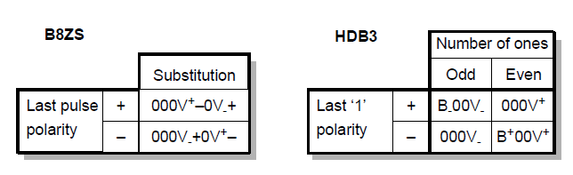
Figure 1.2 B8ZS and HDB3 coding. Bipolar violations are: V+ a positive level and V- negative.
High-density bipolar three zeroes
High-density bipolar three zeroes (HDB3) is similar to B8ZS, but limits the maxi- mum number of transmitted consecutive zeros to three (see Figure 1.5). The basic idea consists of replacing a series of four bits that are equal to “0” with a code word “000V” or “B00V,” where “V” is a pulse that violates the AMI law of alternate po- larity, and B it is for balancing the polarity.
- “B00V” is used when, until the previous pulse, the coded signal presents a dc component that is not null (the number of positive pulses is not compensated by the number of negative pulses).
- “000V” is used under the same conditions as above, when, until the previous pulse, the dc component is null (see Figure 1.6).
- The pulse “B” (for balancing), which respects the AMI alternation rule and has positive or negative polarity, ensuring that two consecutive “V” pulses will have different polarity.
Coded mark inverted
The coded mark inverted (CMI) code, also based on AMI, is used instead of HDB3 at high transmission rates, because of the greater simplicity of CMI coding and de- coding circuits compared to the HDB3 for these rates. In this case, a “1” is transmit- ted according to the AMI rule of alternate polarity, with a negative level of voltage during the first half of the period of the pulse, and a positive level in the second half. The CMI code has the following characteristics (see Figure 1.1):
- The spectrum of a CMI signal cancels out the components at very low frequencies.
- It allows for the clock to be recovered properly, like the HDB3 code.
- The bandwidth is greater than that of the spectrum of the same signal coded in AMI.
Unlock Premium Content
Join over 400K+ optical network professionals worldwide. Access premium courses, advanced engineering tools, and exclusive industry insights.
Already have an account? Log in here