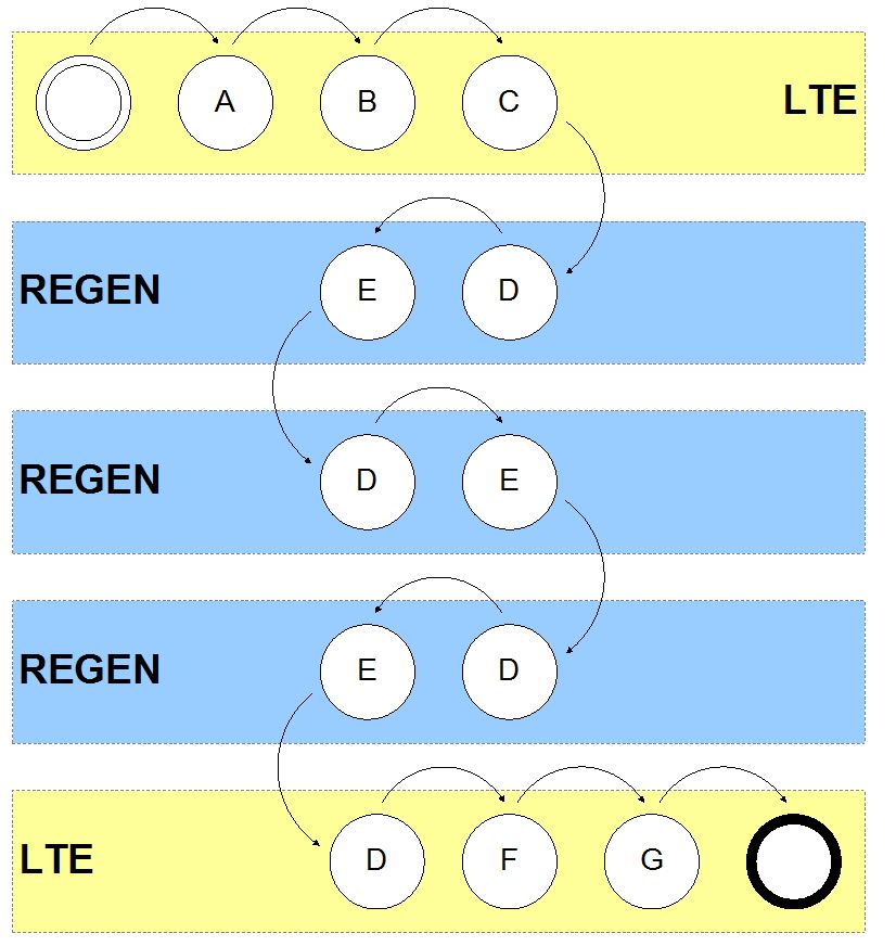
The first thing to note is that for each frame there are two sets of 20 parity bits. One set is associated with the end to end post FEC BER. The other is used to measure the span by span raw BER. The points at which these parity bits are terminated are illustrated below.

|
Processing point |
Process description |
|
A |
Calculate and insert the post FEC parity bits (those over which FEC is calculated) over the frame up to and including the MS OH. |
|
B |
Encode FEC over the frame up to and including the MS OH. |
|
C |
Calculate and insert the pre FEC parity bits (those over which FEC is not calculated) over the frame up to and including the RS OH. |
|
D |
Terminate the raw BER based on the pre FEC parity bits. |
|
E |
Re-calculate the pre FEC parity bits over the frame up to, and including, the RS OH. |
|
F |
Decode FEC to produce the final data. |
|
G |
Terminate the post FEC BER based on the post FEC parity bits. |
We can use the raw BER extracted at each RS terminating point (regens and LTEs) to estimate the post FEC BER. Note that this estimate is based on an assumption of a Poisson distribution of errors. In contrast the real post FEC BER can only be extracted at the MS terminating equipment (LTEs), and this is used to feed into the PM error counts.
Following are the terminologies you will come across when referring FEC Performance parameters:
PRE-FEC BER are the bit errors caused by attenuation, ageing, temperature changes of the optical fiber. PRE-FEC indicates that the signal on the optical fiber is FEC
encoded. The FEC decoder will recover the original signal, but depending on the PRE_FEC BER it will succeed to recover the original signal completely without errors.
Or, if the BER on the fiber is too high, the recovered signal will contain bit errors.
If the signal was FEC encoded the remaining bit errors after the decoder are called POST_FEC BER.
The NO_FEC BER are the bit errors detected when no FEC coding is used on the optical fiber.
Uncorrected words are the word that FEC is not able to corrects.It shows that the current FEC is not able to correct anymore and we need to look for more advance FEC.
Unlock Premium Content
Join over 400K+ optical network professionals worldwide. Access premium courses, advanced engineering tools, and exclusive industry insights.
Already have an account? Log in here


