
Last Updated: August 16, 2025
3 min read
179
Optical Fiber Link Design requirements
The optical link design essentially is putting the various optical components, so that information can be transmitted satisfactorily. The satisfactoriness of the transmission can be defined in terms of some characteristic parameters.The user generally specifies the distance over which the information is to be sent and the data rate to be transmitted. The Designer then has to find the specification of the system components.
The designer generally has to define some additional criteria either as per the standards or as per the user specifications.
The Design criteria are given in the following.
Primary Design Criteria
- Data Rate
- Link length
Additional Design Parameters
- Modulation format eg Analog/digital
-
-
-
-
-
-
- Depends upon the type of signals user want to transmit. For example if it is a TV signal, then may be analog transmission is more suited as it requires less bandwidth and better linearity. On the other hand if data or sampled voice is to be transmitted, digital format may be more appropriate.
- The digital signals have to be further coded to suite the transmission medium and for error correction.
-
-
-
-
-
-
- System fidelity: BER, SNR
-
-
-
-
-
-
- The system fidelity defines the correctness of the data received at the receiver.
- For digital transmission it is measured by the Bit Error Ratio (BER) . The BER is defined as:-

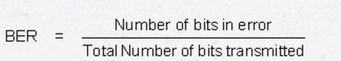
- In optical system, the BER has to be less than 10E-9
- For analog system, the quality parameter is the Signal-to-noise (SNR) ratio. In addition, there is a parameter called the inter-modulation distortion, which describes the linearity of the system.
-
-
-
-
-
-
- Cost : Components, installation, maintenance
-
-
-
-
-
- Cost is one of the important issues of the link design.
- The cost has three components, components, installation and maintenance.
- The component and the installations cost are the initial costs. Generally, the installation cost is much higher than the component cost for long links. This is especially true for laying the optical cable. It is therefore appropriate to lay the cables keeping in view the future needs.
- The optical link is suppose is supposed to work for at least 25years. The maintenance costs are as important as the initial cost. An initial cheaper system might end up into higher expenses in maintenance and therefore turn out to be more expensive as a whole.
-
-
-
-
-
- Upgradeability
-
-
-
-
-
- The optical fiber technology is changing very rapidly and the data rates are increasing steadily.
- The system should be able to adopt new technology, as well should be able to accommodate higher data rates with least possible changes.
-
-
-
-
-
- Commercial availability
-
-
-
-
- Depending upon which part of the world one is, the availability of the components and the systems may be an issue.
-
-
-
-
ref:http://nptel.ac.in/courses/117101054/16


