7 min read

Maintenance Challenges with Hollow Core Fiber
Critical Considerations for Field Operations, Splicing, and Long-Term Network Reliability
Introduction
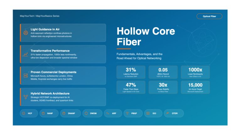
Hollow core fiber (HCF) represents a fundamental departure from conventional solid-core optical fiber technology. Unlike traditional single-mode fibers where light propagates through a solid silica core, hollow core fibers guide light through an air-filled void surrounded by a specially designed silica microstructure. This innovative architecture enables light to travel through a gaseous medium rather than solid glass, offering unique advantages including reduced latency (approximately 30% faster than conventional fiber), minimal nonlinear effects, and the potential for ultra-low attenuation reaching 0.11 dB/km at 1550 nm wavelength.
While hollow core fiber technology promises revolutionary performance improvements, particularly in applications where latency is critical such as high-frequency trading networks, data center interconnects, and future submarine cable systems, the maintenance and operational aspects of HCF present significant challenges that differ markedly from traditional fiber infrastructure. The specialized structure of hollow core fibers, combined with their sensitivity to environmental factors and the need for precise handling procedures, creates a complex set of maintenance requirements that network operators and field technicians must understand and address.
Current hollow core fiber production capabilities remain limited compared to conventional fiber manufacturing, with HCF being significantly more expensive and available only from specialized suppliers. Despite these limitations, HCF has found niche markets where its unique properties justify the additional cost and complexity. As the technology matures and deployment expands, understanding the maintenance challenges becomes increasingly important for ensuring long-term network reliability and operational efficiency.
This article examines the critical maintenance challenges associated with hollow core fiber technology, providing network engineers and field technicians with practical insights into installation procedures, splicing techniques, testing methodologies, environmental considerations, and best practices for ensuring reliable operation of HCF-based optical networks.
Figure 1: Hollow Core Fiber Structure vs Conventional Single-Mode Fiber
Core Maintenance Challenges
1. Splicing and Connection Complexity
Splicing hollow core fiber presents one of the most significant maintenance challenges. Unlike conventional single-mode fiber where fusion splicing involves melting and fusing solid silica cores together, HCF splicing must preserve the hollow core structure while achieving low-loss connections. The primary difficulty stems from the fact that traditional fusion splicing parameters optimized for solid-core fiber can collapse or damage the delicate air-core structure of HCF.
Fusion Splicing Challenges
The fusion splicing process for hollow core fiber requires precise control of several critical parameters that differ significantly from conventional fiber splicing:
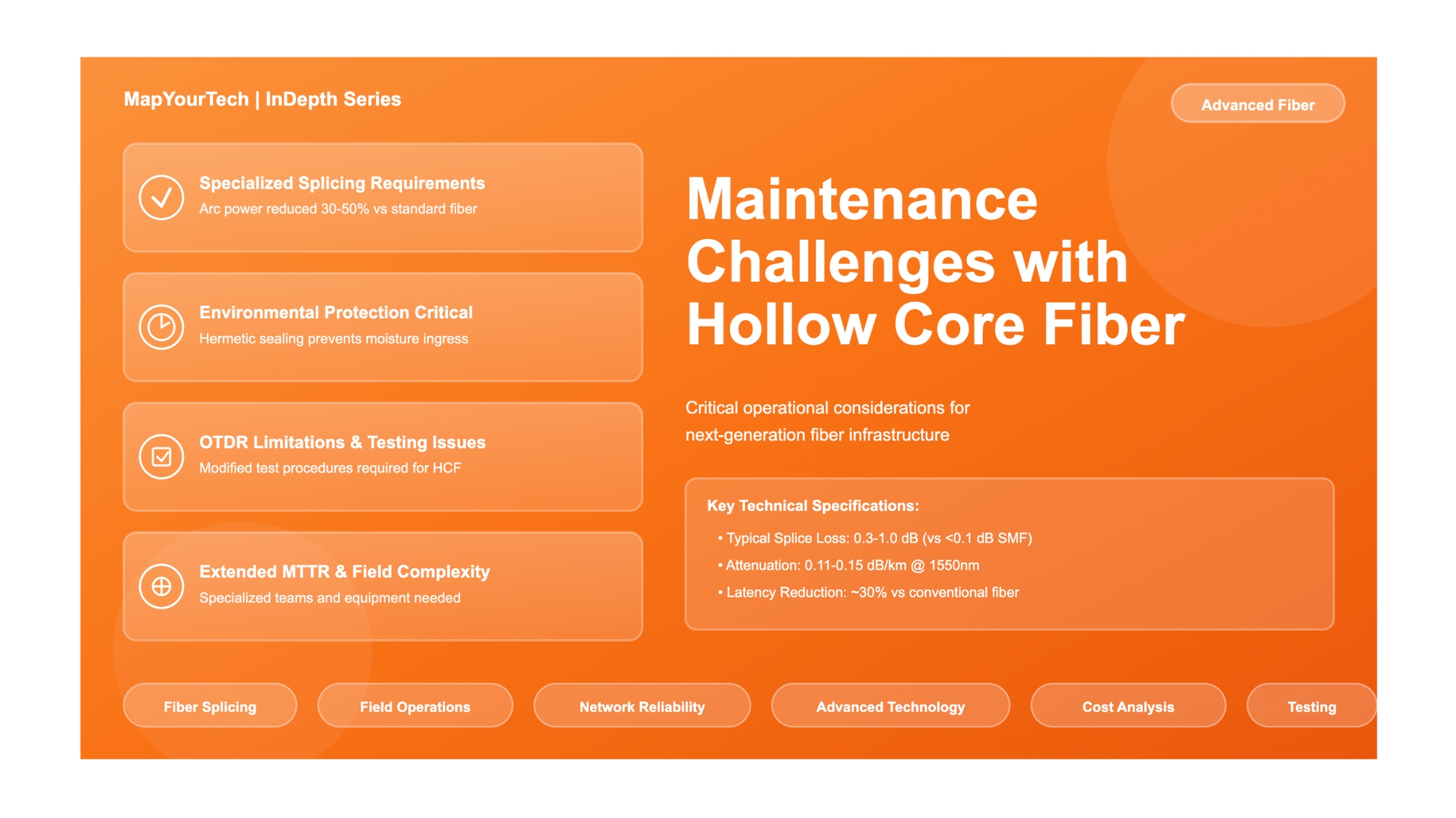
- Arc Power and Duration: Excessive heat can collapse the microstructure or deform the hollow core. Arc power must be reduced by 30-50% compared to standard SMF splicing, typically requiring specialized splicing programs.
- Core Alignment Precision: The hollow core diameter (typically 30-40 μm) is larger than conventional SMF core (9 μm), but alignment tolerance is actually tighter due to mode field mismatch sensitivity. Alignment accuracy within ±0.5 μm is typically required.
- Cleave Quality: End-face preparation is more critical for HCF. Any contamination or imperfection can affect the air-core interface and increase splice loss significantly. Cleave angles must be maintained within 0.5 degrees.
- Splice Loss Variability: While conventional SMF splices achieve losses below 0.1 dB consistently, HCF splices typically exhibit losses between 0.3-1.0 dB, with significant variability depending on fiber type and splicing conditions.
Many field technicians trained on conventional fiber splicing require extensive retraining and specialized equipment to work with HCF. Standard fusion splicers may not have the appropriate programs or precision required for HCF splicing, necessitating investment in advanced splicing platforms with HCF-specific capabilities.
Mechanical Splicing Limitations
Mechanical splicing, which uses precision alignment fixtures to mate fibers without fusion, is even more problematic for HCF. The index-matching gel typically used in mechanical splices is designed for solid-core fiber and does not work effectively with the air-core structure. Additionally, the larger mode field diameter and unique optical properties of HCF result in higher mechanical splice losses (typically 1.5-3.0 dB) compared to fusion splicing, making mechanical connections generally unsuitable except for temporary field repairs.
2. Environmental Sensitivity and Protection
Hollow core fiber exhibits heightened sensitivity to environmental factors that can affect its performance and long-term reliability. The air-filled core makes HCF more susceptible to environmental ingress and contamination compared to solid-core fiber.
Moisture and Humidity Concerns
The hollow core structure creates pathways for moisture ingress, particularly at splice points, connectors, and fiber breaks. Moisture infiltration can cause:
- Attenuation Increase: Water vapor in the core can absorb optical signals, particularly at specific wavelengths, increasing attenuation by 0.1-0.5 dB/km or more depending on humidity levels.
- Microstructure Degradation: Long-term moisture exposure can lead to physical degradation of the antiresonant microstructure through chemical processes.
- Propagation Mode Changes: Moisture can affect the refractive index profile and alter the waveguiding properties of the fiber.
Field installations require hermetic sealing of all splice enclosures and connection points. Standard splice closures designed for conventional fiber may not provide adequate protection for HCF. Specialized hermetic splice enclosures with desiccant materials and pressure monitoring are often necessary to maintain low humidity levels within the protected environment.
Temperature Stability
While HCF generally exhibits lower temperature sensitivity than conventional fiber in terms of transmission characteristics, the mechanical stability of the microstructure can be affected by thermal cycling. Repeated expansion and contraction can introduce microbends or stress points in the delicate antiresonant tubes. Installations in environments with extreme temperature variations require additional protective measures such as temperature-controlled cabinets or specialized cable designs with improved thermal buffering.
3. Testing and Characterization Challenges
Standard fiber testing equipment and procedures developed for conventional single-mode fiber may not work properly or provide accurate results when used with hollow core fiber. This creates significant challenges for installation verification, troubleshooting, and ongoing network monitoring.
OTDR Testing Limitations
Optical Time Domain Reflectometry (OTDR), the industry-standard tool for fiber characterization and fault location, faces several issues with HCF:
- Backscatter Coefficient Difference: HCF has a significantly different backscatter coefficient compared to SMF because light propagates through air rather than silica. This affects OTDR distance measurement accuracy and event detection sensitivity.
- Dead Zones: The mode field mismatch at HCF-to-SMF transition points creates large reflective events that extend OTDR dead zones, making it difficult to characterize closely-spaced events.
- Attenuation Measurement: Standard OTDR attenuation measurement algorithms assume conventional fiber properties and may provide inaccurate results for HCF sections.
- Splice Loss Measurement: The asymmetric loss behavior at HCF splices (different loss in forward vs. reverse direction) complicates bidirectional OTDR analysis.
Field technicians must use specialized OTDR test parameters and interpretation methods for HCF testing. Some OTDR manufacturers have developed HCF-specific testing modes, but these are not universally available. In many cases, alternative testing methods such as insertion loss testing with calibrated light sources and power meters provide more reliable characterization of HCF installations.
Connector Inspection Challenges
Visual inspection of HCF connectors requires specialized microscopy techniques. The hollow core structure appears different under standard fiber inspection microscopes, and technicians must be trained to recognize acceptable vs. problematic conditions specific to HCF. Contamination that might be acceptable on conventional fiber can cause significant loss or damage on HCF due to the air-core interface.
Figure 2: Hollow Core Fiber Splicing Process and Critical Considerations
Operational and Cost Considerations
4. Field Repair and Emergency Response
Emergency repair of hollow core fiber installations presents unique challenges compared to conventional fiber networks. The specialized equipment, materials, and expertise required for HCF maintenance may not be readily available at all field locations, potentially extending repair times significantly.
Emergency Repair Challenges
- Equipment Availability: HCF-capable fusion splicers and specialized test equipment may not be stocked at all field offices or carried by all technician vehicles. Emergency repairs may require dispatching specialized teams with appropriate equipment.
- Spare Fiber Logistics: Maintaining inventories of HCF spare fiber adds cost and complexity. HCF cannot be spliced directly to conventional SMF without mode field adapters or transition components.
- Technician Training: Not all field technicians may be certified to work on HCF. Organizations must maintain a pool of HCF-trained personnel and ensure adequate coverage across service territories.
- Restoration Time: The more complex splicing procedures and potential need for specialized personnel can extend mean time to repair (MTTR) by 2-4 times compared to conventional fiber repairs.
Networks incorporating HCF should implement contingency plans including pre-positioned specialized equipment at strategic locations, redundant path routing where critical latency requirements permit, and maintaining contractual relationships with HCF equipment vendors for expedited replacement component delivery.
5. Total Cost of Ownership
While HCF offers performance advantages, the maintenance-related cost implications must be carefully evaluated when considering deployment. The total cost of ownership for HCF infrastructure significantly exceeds conventional fiber when maintenance factors are considered.
| Cost Factor | Conventional SMF | Hollow Core Fiber | Cost Multiplier |
|---|---|---|---|
| Initial Fiber Cost | $0.50-1.00/meter | $5.00-15.00/meter | 10-15× |
| Fusion Splicer (HCF-capable) | $15,000-30,000 | $40,000-80,000 | 2.5-3× |
| Technician Training (per person) | $2,000-5,000 | $10,000-20,000 | 4-5× |
| Splice Loss Budget Impact | 0.1 dB per splice | 0.5-1.0 dB per splice | 5-10× loss budget |
| Test Equipment (HCF-specific) | $20,000-40,000 | $50,000-100,000 | 2.5-3× |
| Splice Enclosures (hermetic) | $50-150 each | $300-800 each | 4-6× |
| Mean Time to Repair (MTTR) | 2-4 hours typical | 6-12 hours typical | 3× |
| Annual Maintenance Cost | Baseline | 3-5× baseline | 3-5× |
Organizations must justify HCF deployment based on the specific performance requirements of their applications. The technology is most cost-effective in scenarios where latency reduction directly translates to significant business value, such as high-frequency trading networks, where microsecond-level improvements can justify the higher operational costs.
6. Long-Term Reliability and Degradation
The long-term reliability of hollow core fiber in deployed networks remains an area of ongoing investigation. While accelerated aging tests show promising results, the technology has not yet accumulated decades of field deployment data like conventional fiber.
Reliability Concerns
Network operators should be aware of potential long-term degradation mechanisms that may affect HCF performance over 10-25 year deployment timescales. These include gradual attenuation increase due to hydrogen diffusion into the core, mechanical stress effects on the microstructure, and potential coating degradation under environmental exposure. Establishing baseline performance metrics at installation and implementing regular monitoring programs is essential for detecting gradual degradation.
Figure 3: HCF Network Maintenance Workflow and Best Practices
Best Practices and Recommendations
Technical Implementation Guidelines
- Establish HCF Centers of Excellence: Rather than training all technicians on HCF maintenance, designate specialized teams with deep expertise in hollow core fiber technology. This concentrated approach ensures consistent quality and allows for more comprehensive training.
- Implement Redundancy Where Possible: For critical HCF links, deploy redundant paths to allow maintenance without service interruption. The higher repair complexity makes path diversity more valuable than with conventional fiber.
- Use Transition Points Strategically: Minimize HCF-to-SMF interfaces and locate them at controlled facilities rather than field locations. Each transition point introduces loss and potential failure modes.
- Maintain Comprehensive Baseline Documentation: Document initial installation parameters, splice losses, and environmental conditions thoroughly. This baseline enables effective degradation monitoring and troubleshooting.
- Invest in Specialized Test Equipment: Standard OTDR and test equipment may provide inaccurate results with HCF. Ensure test equipment is appropriate for HCF characterization or develop correlation factors for standard equipment.
- Establish Environmental Monitoring: Deploy humidity and temperature sensors in splice enclosures and track data continuously. Early detection of environmental ingress prevents catastrophic failures.
- Create Detailed Maintenance Procedures: Develop step-by-step procedures specific to HCF maintenance, including photographs and decision trees. Consistency in maintenance practices is critical for reliability.
- Plan for Technology Evolution: HCF technology continues to evolve rapidly. Stay engaged with suppliers on new developments in splicing techniques, protection methods, and testing procedures.
When to Deploy HCF: Decision Framework
- Application requires microsecond-level latency reduction that justifies 3-5× higher operational costs
- Link distances are compatible with current HCF attenuation (typically under 50-100 km for unrepeatered systems)
- Controlled installation environment available (not harsh outdoor conditions)
- Organization has capability to maintain specialized equipment and trained personnel
- Higher initial and ongoing costs are acceptable given specific application benefits
- Long-term technology support and spare part availability can be assured
- Risk of extended outage times is acceptable or mitigated by redundancy
Conclusion
Hollow core fiber technology offers compelling performance advantages for specific applications where ultra-low latency and minimal nonlinear effects are critical requirements. The ability to guide light through air rather than solid glass fundamentally changes the physics of signal propagation, enabling capabilities that conventional fiber cannot match. Recent achievements in attenuation reduction to 0.11 dB/km demonstrate the technology's maturation and potential for broader deployment.
However, the maintenance challenges associated with HCF remain significant and must be carefully considered in deployment planning. From specialized splicing requirements and environmental sensitivity to higher repair complexity and cost implications, HCF introduces operational challenges that differ fundamentally from conventional fiber infrastructure. Organizations must invest in specialized equipment, comprehensive training programs, and revised maintenance procedures to ensure reliable HCF network operation.
The decision to deploy hollow core fiber should be based on a thorough analysis of application requirements, operational capabilities, and total cost of ownership. For applications where latency reduction translates directly to business value—such as high-frequency trading networks, certain data center interconnects, or specialized sensing applications—the performance benefits can justify the additional complexity and cost. For general-purpose telecommunications applications, conventional single-mode fiber remains the more practical choice given current HCF limitations and maintenance requirements.
As hollow core fiber technology continues to evolve, with ongoing improvements in manufacturing processes, splicing techniques, and field handling procedures, some of the current maintenance challenges may be mitigated. Network operators considering HCF deployment should maintain close relationships with technology suppliers, participate in industry standards development, and carefully monitor field experience from early adopters. With proper planning, specialized expertise, and appropriate application selection, hollow core fiber can be successfully deployed and maintained as a valuable addition to advanced optical network infrastructure.
References
[1] ITU-T Recommendation G.650.1 – Definitions and test methods for linear, deterministic attributes of single-mode fiber and cable.
[2] IEEE 802.3cn – Amendment: Physical Layers and Management Parameters for 50 Gb/s, 200 Gb/s, and 400 Gb/s operation.
[3] Bradley, T.D., et al., "Antiresonant hollow core fiber with 0.11 dB/km attenuation at 1550 nm wavelength," Nature Photonics Research.
[4] Poletti, F., "Nested antiresonant nodeless hollow core fiber," Optics Express.
[5] IEC 61300-3-35 – Fiber optic interconnecting devices and passive components – Basic test and measurement procedures – Examinations and measurements for hollow core fiber assemblies.
Recommended Reading:
Sanjay Yadav, "Optical Network Communications: An Engineer's Perspective" – Bridge the Gap Between Theory and Practice in Optical Networking
Developed by MapYourTech Team
For educational purposes in Optical Networking Communications Technologies
Unlock Premium Content
Join over 400K+ optical network professionals worldwide. Access premium courses, advanced engineering tools, and exclusive industry insights.
Already have an account? Log in here