Animated CTA Banner
MapYourTech
MapYourTech has always been about YOUR tech journey, YOUR questions, YOUR thoughts, and most importantly, YOUR growth. It’s a space where we "Map YOUR Tech" experiences and empower YOUR ambitions.
To further enhance YOUR experience, we are working on delivering a professional, fully customized platform tailored to YOUR needs and expectations.
Thank you for the love and support over the years. It has always motivated us to write more, share practical industry insights, and bring content that empowers and inspires YOU to excel in YOUR career.
We truly believe in our tagline:
“Share, explore, and inspire with the tech inside YOU!”
Let us know what YOU would like to see next! Share YOUR thoughts and help us deliver content that matters most to YOU.
Share YOUR Feedback
Tag

Bit error rate

Browsing
Items HD-FEC SD-FEC
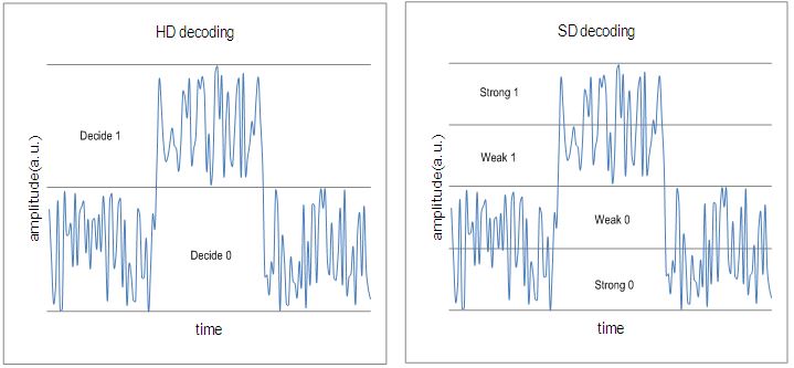
Definition Decoding based on hard-bits(the output is quantized only to two levels) is called the “HD(hard-decision) decoding”, where each bit is considered definitely one or zero. Decoding based on soft-bits(the output is quantized to more than two levels) is called the “SD(soft-decision) decoding”, where not only one or zero decision but also confidence information for the decision are provided.
Application Generally for non-coherent detection optical systems, e.g.,  10 Gbit/s, 40 Gbit/s, also for some coherent detection optical systems with higher OSNR coherent detection optical systems, e.g.,  100 Gbit/s,400 Gbit/s.
Electronics Requirement ADC(Analogue-to-Digital Converter) is not necessary in the receiver. ADC is required in the receiver to provide soft information, e.g.,  coherent detection optical systems.
specification general FEC per [ITU-T G.975];super FEC per [ITU-T G.975.1]. vendor specific
typical scheme Concatenated RS/BCH LDPC(Low density parity check),TPC(Turbo product code)
complexity medium high
redundancy ratio generally 7% around 20%
NCG about 5.6 dB for general FEC;>8.0 dB for super FEC. >10.0 dB
 Example(If you asked your friend about traffic jam status on roads and he replies) maybe fully jammed or free  50-50  but I found othe way free or less traffic

The Bit Error Ratio (BER) is often specified as a performance parameter of a transmission system, which needs to be verified during investigation. Designing an experiment to demonstrate adequate BER performance is not, however, as straightforward as it appears since the number of errors detected over a practical measurement time is generally small. It is, therefore, not sufficient to quote the BER as simply the ratio of the number of errors divided by the number of bits transmitted during the measurement period, instead some knowledge of the statistical nature of the error distribution must first be assumed.

The bit error rate (BER) is the most significant performance parameter of any digital communications system. It is a measure of the probability that any given bit will have been received in error. For example a standard maximum bit error rate specified for many systems is 10-9. This means that the receiver is allowed to generate a maximum of 1 error in every 109 bits of information transmitted or, putting it another way, the probability that any received bit is in error is 10-9.

 The BER depends primarily on the signal to noise ratio (SNR) of the received signal which in turn is determined by the transmitted signal power, the attenuation of the link, the link dispersion and the receiver noise. The S/N ratio is generally quoted for analog links while the bit-error-rate (BER) is used for digital links. BER is practically an inverse function of S/N. There must be a minimum power at the receiver to provide an acceptable S/N or BER. As the power increases, the BER or S/N improves until the signal becomes so high it overloads the receiver and receiver performance degrades rapidly.

 The formula used to calculate residual BER assumes a gaussian error distribution:

C = 1 – e–nb

C = Degree of confidence required

(0.95 = 95% confidence)

n = No. of bits examined with no error found.

b = Upper bound on BER with a confidence C

(b = 10–15)

To determine the length of time, that is, the number of bits needed to test for (at a given bit rate), requires the above equation to be transposed:

n = loge(1 – C)/b


So, to test for a residual BER of 10–13 with a 95% confidence limit requires a test pattern equal to 3 x 1013 bits. This equates to only 0.72 hours using an OC-192c/STM-64c payload rather than 55.6 hours using an STS-3c/VC-4 bulk filled payload (149.76 Mb/s).The graph in Figure plots test time versus residual BER and shows the difference in test time for OC-192c/STM-64c payloads versus an OC-48c/STM-16c payload.The graphs are plotted for different confidence limits and they clearly indicate that the payload capacity is the dominant factor in improving the test time and not the confidence limit. Table 1 shows the exact test times for each BER threshold and confidence limit.


collected from::Product Note-OmniBER