Tag

Communication technology

Browsing


In today’s world, where digital information rules, keeping networks secure is not just important—it’s essential for the smooth operation of all our communication systems. Optical Transport Networking (OTN), which follows rules set by standards like ITU-T G.709 and ITU-T G.709.1, is leading the charge in making sure data gets where it’s going safely. This guide takes you through the essentials of OTN secure transport, highlighting how encryption and authentication are key to protecting sensitive data as it moves across networks.

The Introduction of OTN Security

Layer 1 encryption, or OTN security (OTNsec), is not just a feature—it’s a fundamental aspect that ensures the safety of data as it traverses the complex web of modern networks. Recognized as a market imperative, OTNsec provides encryption at the physical layer, thwarting various threats such as control management breaches, denial of service attacks, and unauthorized access.

OTNsec

Conceptualizing Secure Transport

OTN secure transport can be visualized through two conceptual approaches. The first, and the primary focus of this guide, involves the service requestor deploying endpoints within its domain to interface with an untrusted domain. The second approach sees the service provider offering security endpoints and control over security parameters, including key management and agreement, to the service requestor.

OTN Security Applications

As network operators and service providers grapple with the need for data confidentiality and authenticity, OTN emerges as a robust solution. From client end-to-end security to service provider path end-to-end security, OTN’s applications are diverse.

Client End-to-End Security

This suite of applications ensures that the operator’s OTN network remains oblivious to the client layer security, which is managed entirely within the customer’s domain. Technologies such as MACsec [IEEE 802.1AE] for Ethernet clients provide encryption and authentication at the client level.Following are some of the scenerios.

Client end-to-end security (with CPE)

Client end-to-end security (without CPE)
DC, content or mobile service provider client end-to-end security

Service Provider CPE End-to-End Security

Service providers can offer security within the OTN service of the operator’s network. This scenario sees the service provider managing key agreements, with the UNI access link being the only unprotected element, albeit within the trusted customer premises.

OTNsec

Service provider CPE end-to-end security

OTN Link/Span Security

Operators can fortify their network infrastructure using encryption and authentication on a per-span basis. This is particularly critical when the links interconnect various OTN network elements within the same administrative domain.

OTN link/span security

OTN link/span leased fibre security

Second Operator and Access Link Security

When services traverse the networks of multiple operators, securing each link becomes paramount. Whether through client access link security or OTN service provider access link security, OTN facilitates a protected handoff between customer premises and the operator.

OTN leased service security

Multi-Layered Security in OTN

OTN’s versatility allows for multi-layered security, combining protocols that offer different characteristics and serve complementary functions. From end-to-end encryption at the client layer to additional encryption at the ODU layer, OTN accommodates various security needs without compromising on performance.

OTN end-to-end security (with CPE)

Final Observations

OTN security applications must ensure transparency across network elements not participating as security endpoints. Support for multiple levels of ODUj to ODUk schemes, interoperable cipher suite types for PHY level security, and the ability to handle subnetworks and TCMs are all integral to OTN’s security paradigm.

Layered security example

This blog provides a detailed exploration of OTN secure transport, encapsulating the strategic implementation of security measures in optical networks. It underscores the importance of encryption and authentication in maintaining data integrity and confidentiality, positioning OTN as a critical component in the infrastructure of secure communication networks.

By adhering to these security best practices, network operators can not only safeguard their data but also enhance the overall trust in their communication systems, paving the way for a secure and reliable digital future.

References

More Detail article can be read on ITU-T at

https://www.itu.int/rec/T-REC-G.Sup76/en

Power Change during add/remove of channels on filters

The power change can be quantified as the ratio between the number of channels at the reference point after the channels are added or dropped and the number of channels at that reference point previously. We can consider composite power here and each channel at same optical power in dBm.

So whenever we add or delete number of channels from a MUX/DEMUX/FILTER/WSS following equations define the new changed power.

For the case when channels are added (as illustrated on the right side of Figure 1 ):

where:

A   is the number of added channels

U   is the number of undisturbed channels

For the case when channels are dropped (as illustrated on the left side of Figure 1):


where:

D   is the number of dropped channels

U   is the number of undisturbed channels


 Figure 1

For example:

–           adding 7 channels with one channel undisturbed gives a power change of +9 dB;

–           dropping 7 channels with one channel undisturbed gives a power change of –9 dB;

–           adding 31 channels with one channel undisturbed gives a power change of +15 dB;

–           dropping 31 channels with one channel undisturbed gives a power change of –15 dB;

refer ITU-T G.680 for further study.

Items HD-FEC SD-FEC
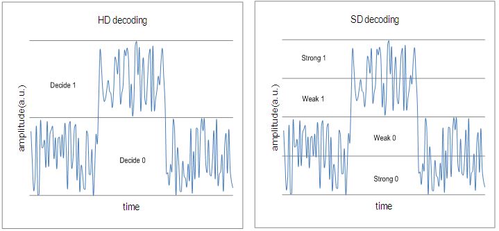
Definition Decoding based on hard-bits(the output is quantized only to two levels) is called the “HD(hard-decision) decoding”, where each bit is considered definitely one or zero. Decoding based on soft-bits(the output is quantized to more than two levels) is called the “SD(soft-decision) decoding”, where not only one or zero decision but also confidence information for the decision are provided.
Application Generally for non-coherent detection optical systems, e.g.,  10 Gbit/s, 40 Gbit/s, also for some coherent detection optical systems with higher OSNR coherent detection optical systems, e.g.,  100 Gbit/s,400 Gbit/s.
Electronics Requirement ADC(Analogue-to-Digital Converter) is not necessary in the receiver. ADC is required in the receiver to provide soft information, e.g.,  coherent detection optical systems.
specification general FEC per [ITU-T G.975];super FEC per [ITU-T G.975.1]. vendor specific
typical scheme Concatenated RS/BCH LDPC(Low density parity check),TPC(Turbo product code)
complexity medium high
redundancy ratio generally 7% around 20%
NCG about 5.6 dB for general FEC;>8.0 dB for super FEC. >10.0 dB
 Example(If you asked your friend about traffic jam status on roads and he replies) maybe fully jammed or free  50-50  but I found othe way free or less traffic

In a non-coherent WDM system, each optical channel on the line side uses only one binary channel to carry service information. The service transmission rate on each optical channel is called bit rate while the binary channel rate is called baud rateIn this sense, the baud rate was equal to the bit rate. The spectral width of an optical signal is determined by the baud rate. Specifically, the spectral width is linearly proportional to the baud rate, which means a higher baud rate generates a larger spectral width.

  • Baud (pronounced as /bɔ:d/ and abbreviated as “Bd”) is the unit for representing the data communication speed. It indicates the signal changes occurring in every second on a device, for example, a modulator-demodulator (modem). During encoding, one baud (namely, the signal change) actually represents two or more bits. In the current high-speed modulation techniques, each change in a carrier can transmit multiple bits, which makes the baud rate different from the transmission speed.

In practice, the spectral width of the optical signal cannot be larger than the frequency spacing between WDM channels; otherwise, the optical spectrums of the neighboring WDM channels will overlap, causing interference among data streams on different WDM channels and thus generating bit errors and a system penalty.

For example, the spectral width of a 100G BPSK/DPSK signal is about 50 GHz, which means a common 40G BPSK/DPSK modulator is not suitable for a 50 GHz channel spaced 100G system because it will cause a high crosstalk penalty. When the baud rate reaches 100 Gbaud/s, the spectral width of the BPSK/DPSK signal is greater than 50 GHz. Thus, it is impossible to achieve 50 GHz channel spacing in a 100G BPSK/DPSK transmission system.

(This is one reason that BPSK cannot be used in a 100G coherent system. The other reason is that high-speed ADC devices are costly.)

A 100G coherent system must employ new technology. The system must employ more advanced multiplexing technologies so that an optical channel contains multiple binary channels. This reduces the baud rate while keeping the line bit rate unchanged, ensuring that the spectral width is less than 50 GHz even after the line rate is increased to 100 Gbit/s. These multiplexing technologies include quadrature phase shift keying (QPSK) modulation and polarization division multiplexing (PDM).