Tag

High-Speed Data Transmission

Browsing

In this ever-evolving landscape of optical networking, the development of coherent optical standards, such as 400G ZR and ZR+, represents a significant leap forward in addressing the insatiable demand for bandwidth, efficiency, and scalability in data centers and network infrastructure. This technical blog delves into the nuances of these standards, comparing their features, applications, and how they are shaping the future of high-capacity networking. ZR stands for “Ze Best Range” and ZR+ is reach “Ze Best Range plus”

Introduction to 400G ZR

The 400G ZR standard, defined by the Optical Internetworking Forum (OIF), is a pivotal development in the realm of optical networking, setting the stage for the next generation of data transmission over optical fiber’s. It is designed to facilitate the transfer of 400 Gigabit Ethernet over single-mode fiber across distances of up to 120 kilometers without the need for signal amplification or regeneration. This is achieved through the use of advanced modulation techniques like DP-16QAM and state-of-the-art forward error correction (FEC).

Key features of 400G ZR include:

  • High Capacity: Supports the transmission of 400 Gbps using a single wavelength.
  • Compact Form-Factor: Integrates into QSFP-DD and OSFP modules, aligning with industry standards for data center equipment.
  • Cost Efficiency: Reduces the need for external transponders and simplifies network architecture, lowering both CAPEX and OPEX.

Emergence of 400G ZR+

Building upon the foundation set by 400G ZR, the 400G ZR+ standard extends the capabilities of its predecessor by increasing the transmission reach and introducing flexibility in modulation schemes to cater to a broader range of network topologies and distances. The OpenZR+ MSA has been instrumental in this expansion, promoting interoperability and open standards in coherent optics.

Key enhancements in 400G ZR+ include:

  • Extended Reach: With advanced FEC and modulation, ZR+ can support links up to 2,000 km, making it suitable for longer metro, regional, and even long-haul deployments.
  • Versatile Modulation: Offers multiple configuration options (e.g., DP-16QAM, DP-8QAM, DP-QPSK), enabling operators to balance speed, reach, and optical performance.
  • Improved Power Efficiency: Despite its extended capabilities, ZR+ maintains a focus on energy efficiency, crucial for reducing the environmental impact of expanding network infrastructures.

ZR vs. ZR+: A Comparative Analysis

Feature. 400G ZR 400G ZR+
Reach Up to 120 km Up to 2,000 km
Modulation DP-16QAM DP-16QAM, DP-8QAM, DP-QPSK
Form Factor QSFP-DD, OSFP QSFP-DD, OSFP
Application Data center interconnects Metro, regional, long-haul

Adding few more interesting table for readersZR

Based on application

Product Reach Client Formats Data Rate & Modulation Wavelength Tx Power Connector Fiber Interoperability Application
800G ZR+ 4000 km+ 100GbE
200GbE
400GbE
800GbE
800G Interop PCS 
 600G PCS 
 400G PCS
1528.58  to
 1567.34
>+1 dBm (with TOF) LC SMF OpenROADM interoperable PCS Ideal for metro/regional Ethernet data center and service provider network interconnects
800ZR 120 km 100GbE
200GbE
400GbE
800G 16QAM 
 600G PCS 
 400G Interop
QPSK/16QAM 
 PCS
1528.58  to
 1567.34
-11 dBm to -2 dBm LC SMF OIF 800ZR
 OpenROADM Interop PCS
 OpenZR+
Ideal for amplified single-span data center interconnect applications
400G Ultra Long Haul 4000 km+ 100GbE
200GbE
400GbE
400G Interoperable
QPSK/16QAM 
 PCS
1528.58  to
 1567.34
>+1 dBm (with TOF) LC SMF OpenROADM Interop PCS Ideal for long haul and ultra-long haul service provider ROADM network applications
Bright 400ZR+ 4000 km+ 100GbE
200GbE
400GbE OTUCn
OTU4
400G 16QAM 
 300G 8QAM 
 200G/100G QPSK
1528.58  to
 1567.34
>+1 dBm (with TOF) LC SMF OpenZR+
 OpenROADM
Ideal for metro/regional and service provider ROADM network applications
400ZR 120 km 100GbE
200GbE
400GbE
400G 16QAM 1528.58  to
 1567.34
>-10 dBm LC SMF OIF 400ZR Ideal for amplified single span data center interconnect applications
OpenZR+ 4000 km+ 100GbE
200GbE
400GbE
400G 16QAM 
 300G 8QAM 
 200G/100G QPSK
1528.58  to
 1567.34
>-10 dBm LC SMF OpenZR+
 OpenROADM
Ideal for metro/regional Ethernet data center and service provider network interconnects
400G ER1 45 km 100GbE
400GbE
400G 16QAM Fixed C to
band
>12.5 dB Link Budget LC SMF OIF 400ZR application code 0x02
 OpenZR+
Ideal for unamplified point-to-point links


*TOF: Tunable Optical Filter

The Future Outlook

The advent of 400G ZR and ZR+ is not just a technical upgrade; it’s a paradigm shift in how we approach optical networking. With these technologies, network operators can now deploy more flexible, efficient, and scalable networks, ready to meet the future demands of data transmission.

Moreover, the ongoing development and expected introduction of XR optics highlight the industry’s commitment to pushing the boundaries of what’s possible in optical networking. XR optics, with its promise of multipoint capabilities and aggregation of lower-speed interfaces, signifies the next frontier in coherent optical technology.


Reference

Acacia Introduces 800ZR and 800G ZR+ with Interoperable PCS in QSFP-DD and OSFP

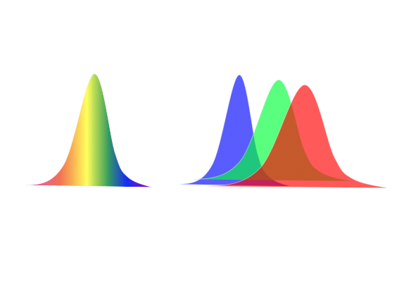
Chromatic dispersion affects all optical transmissions to some degree.These effects become more pronounced as the transmission rate increases and fiber length increases. 

Factors contributing to increasing chromatic dispersion signal distortion include the following:

1. Laser spectral width, modulation method, and frequency  chirp. Lasers with wider spectral widths and chirp have shorter dispersion limits. It is important to refer to manufacturer specifications to determine the total amount of dispersion that can be tolerated by the lightwave equipment.

2. The wavelength of the optical signal. Chromatic dispersion varies with wavelength in a fiber. In a standard non-dispersion shifted fiber (NDSF G.652), chromatic dispersion is near or at zero at 1310 nm. It increases positively with increasing wavelength and increases negatively for wavelengths less than 1310 nm.

3. The optical bit rate of the transmission laser. The higher the fiber bit rate, the greater the signal distortion effect.
4. The chromatic dispersion characteristics of fiber used in the link. Different types of fiber have different dispersion characteristics.
5. The total fiber link length, since the effect is cumulative along the length of the fiber.
6. Any other devices in the link that can change the link’s total chromatic dispersion including chromatic dispersion compensation modules.
7. Temperature changes of the fiber or fiber cable can cause small changes to chromatic dispersion. Refer to the manufacturer’s fiber cable specifications for values.

Methods to Combat Link Chromatic Dispersion

1. Change the equipment laser with a laser that has a specified longer dispersion limit. This is typically a laser with a more narrow spectral width or a laser that has some form of precompensation. As laser spectral width decreases, chromatic dispersion limit increases.
2. For new construction, deploy NZ-DSF instead of SSMF fiber.NZ-DSF has a lower chromatic dispersion specification.
3. Insert chromatic dispersion compensation modules (DCM) into the fiber link to compensate for the excessive dispersion. The optical loss of the DCM must be added to the link optical loss budget and optical amplifiers may be required to compensate.
4. Deploy a 3R optical repeater (re-amplify, reshape, and retime the signal) once a link reaches chromatic dispersion equipment limit.
5. For long haul undersea fiber deployment, splicing in alternating lengths of dispersion compensating fiber can be considered.
6. To reduce chromatic dispersion variance due to temperature, buried cable is preferred over exposed aerial cable.