Tag

OTUk

Browsing

Forward Error Correction (FEC) has become an indispensable tool in modern optical communication, enhancing signal integrity and extending transmission distances. ITU-T recommendations, such as G.693, G.959.1, and G.698.1, define application codes for optical interfaces that incorporate FEC as specified in ITU-T G.709. In this blog, we discuss the significance of Bit Error Ratio (BER) in FEC-enabled applications and how it influences optical transmitter and receiver performance.

The Basics of FEC in Optical Communications

FEC is a method of error control for data transmission, where the sender adds redundant data to its messages. This allows the receiver to detect and correct errors without the need for retransmission. In the context of optical networks, FEC is particularly valuable because it can significantly lower the BER after decoding, thus ensuring the accuracy and reliability of data across vast distances.

BER Requirements in FEC-Enabled Applications

For certain optical transport unit rates (OTUk), the system BER is mandated to meet specific standards only after FEC correction has been applied. The optical parameters, in these scenarios, are designed to achieve a BER no worse than 10−12 at the FEC decoder’s output. This benchmark ensures that the data, once processed by the FEC decoder, maintains an extremely high level of accuracy, which is crucial for high-performance networks.

Practical Implications for Network Hardware

When it comes to testing and verifying the performance of optical hardware components intended for FEC-enabled applications, achieving a BER of 10−12 at the decoder’s output is often sufficient. Attempting to test components at 10−12 at the receiver output, prior to FEC decoding, can lead to unnecessarily stringent criteria that may not reflect the operational requirements of the application.

Adopting Appropriate BER Values for Testing

The selection of an appropriate BER for testing components depends on the specific application. Theoretical calculations suggest a BER of 1.8×10⁻⁴at the receiver output (Point A) to achieve a BER of 10−12 at the FEC decoder output (Point B). However, due to variations in error statistics, the average BER at Point A may need to be lower than the theoretical value to ensure the desired BER at Point B. In practice, a BER range of 10−5 to 10−6 is considered suitable for most applications.

Conservative Estimation for Receiver Sensitivity

By using a BER of 10−6 for component verification, the measurements of receiver sensitivity and optical path penalty at Point A will be conservative estimates of the values after FEC correction. This approach provides a practical and cost-effective method for ensuring component performance aligns with the rigorous demands of FEC-enabled systems.

Conclusion

FEC is a powerful mechanism that significantly improves the error tolerance of optical communication systems. By understanding and implementing appropriate BER testing methodologies, network operators can ensure their components are up to the task, ultimately leading to more reliable and efficient networks.

As the demands for data grow, the reliance on sophisticated FEC techniques will only increase, cementing BER as a fundamental metric in the design and evaluation of optical communication systems.

References

https://www.itu.int/rec/T-REC-G/e

**Multiplicative factor is just a simple math :eg. for ODU1/OPU1=3824/3808={(239*16)/(238*16)}

Here value of multiplication factor will give the number of times for rise in the frame size after adding header/overhead.

Example:let consider y=(x+delta[x])/xIn terms of OTN frame here delta[x] is increment of Overhead.

As we are using Reed Soloman(255,239) i.e we are dividing 4080bytes in sixteen frames (The forward error correction for the OTU-k uses 16-byte interleaved codecs using a Reed- Solomon S(255,239) code. The RS(255,239) code operates on byte symbols.).Hence 4080/16=255.

Try to understand using OTN frames now. I have tried to make it legible.

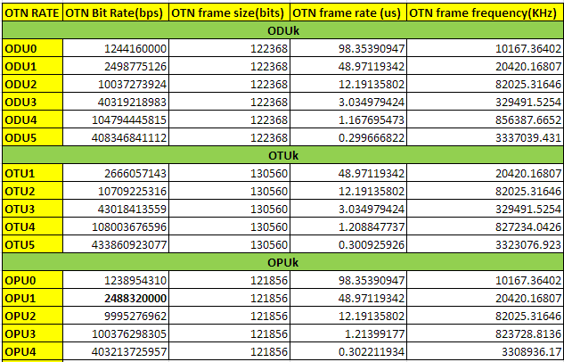
As we know that OPU1 payload rate= 2.488 Gbps (OC48/STM16) and is  frame size is 4*3808 as below.

*After adding OPU1 and ODU1 16 bytes overhead: Frames could be fragmented into following number of chunks.

3808/16 = 238, (3808+16)/16 = 239

So, ODU1 rate: 2.488 x 239/238** ~ 2.499Gbps

*Now after adding  FEC bytes

OTU1 rate: ODU1 x 255/239 = 2.488 x 239/238 x 255/239

=2.488 x 255/238 ~2.667Gbps


Now let’s have a small discussion over different multiplier and divisor scenarios that will make it clearer to understand.

We know that an OTU frame 4 * 4080 bytes (= 255 * 16 * 4)

OPU representing the Payload (3824-16) * 4 * 4 = 3808 bytes (= 238 * 16 * 4) .

OPU1 is exactly the rate of STM-16.

Now,

ODU1 = (3824/3808) * OPU1 = ((16 * 239) / (238 16 *)) * OPU1 = (239/238) * STM-16

OTU1 = (4080/3808) * OPU1 = ((255 * 16) / (238 * 16)) * OPU1 = (255/238) * STM-16


OPU2 contains 16 * 4 = 64 bytes of fixed stuff (FS) added to the 1905 to 1920 .

OPU2 * ((238 * 16 * 4-16 * 4) / (238 * 16 * 4)) = STM-64 rate

OPU2 = 238 / (238-1) * STM-64 = 238/237* STM-64 rate

ODU2 = (239/237) * STM-64 rate ,

similarly


OTU2 = ( 255/237) * STM-64 rate

OPU3 Including 2 * 16 * 4 = 128 fixed stuff (FS) bytes added to the 1265 ~ 1280 and 2545 ~ 2560

OPU3 * ((238 * 16 * 4-2 * 16 * 4) / (238 * 16 * 4)) = rate of STM-256

OPU3 = 238 / (238-2) * STM-256 = 238/236 * STM-256

ODU3 = (239 / 236) * STM-256

OTU3 = (255/236) * STM-256

The OTU4 was required to transport ten ODU2e signals, which have a non-SDH based clock frequency as basis. The OTU4 clock should be based on the same SDH clock as the OTU1, OTU2 and OTU3 and not on the 10GBASE-R clock, which determines the ODU2e frequency. An exercise was performed to determine the necessary divider in the factor 255/divider, and the value 227 was found to meet the requirements (factor 255/227). Note that this first analysis has indicated that a future 400 Gbit/s OTU5 could be created using a factor 255/226 and a 1 Tbit/s OTU6 using a factor 255/225.