Tag

Single-mode Fiber

Browsing

The world of optical communication is undergoing a transformation with the introduction of Hollow Core Fiber (HCF) technology. This revolutionary technology offers an alternative to traditional Single Mode Fiber (SMF) and presents exciting new possibilities for improving data transmission, reducing costs, and enhancing overall performance. In this article, we will explore the benefits, challenges, and applications of HCF, providing a clear and concise guide for optical fiber engineers.

What is Hollow Core Fiber (HCF)?

Hollow Core Fiber (HCF) is a type of optical fiber where the core, typically made of air or gas, allows light to pass through with minimal interference from the fiber material. This is different from Single Mode Fiber (SMF), where the core is made of solid silica, which can introduce problems like signal loss, dispersion, and nonlinearities.

HCF

In HCF, light travels through the hollow core rather than being confined within a solid medium. This design offers several key advantages that make it an exciting alternative for modern communication networks.

Traditional SMF vs. Hollow Core Fiber (HCF)

Single Mode Fiber (SMF) technology has dominated optical communication for decades. Its core is made of silica, which confines laser light, but this comes at a cost in terms of:

  • Attenuation: SMF exhibits more than 0.15 dB/km attenuation, necessitating Erbium-Doped Fiber Amplifiers (EDFA) or Raman amplifiers to extend transmission distances. However, these amplifiers add Amplified Spontaneous Emission (ASE) noise, degrading the Optical Signal-to-Noise Ratio (OSNR) and increasing both cost and power consumption.
  • Dispersion: SMF suffers from chromatic dispersion (CD), requiring expensive Dispersion Compensation Fibers (DCF) or power-hungry Digital Signal Processing (DSP) for compensation. This increases the size of the transceiver (XCVR) and overall system costs.
  • Nonlinearity: SMF’s inherent nonlinearities limit transmission power and distance, which affects overall capacity. Compensation for these nonlinearities, usually handled at the DSP level, increases the system’s complexity and power consumption.
  • Stimulated Raman Scattering (SRS): This restricts wideband transmission and requires compensation mechanisms at the amplifier level, further increasing cost and system complexity.

In contrast, Hollow Core Fiber (HCF) offers significant advantages:

  • Attenuation: Advanced HCF types, such as Nested Anti-Resonant Nodeless Fiber (NANF), achieve attenuation rates below 0.1 dB/km, especially in the O-band, matching the performance of the best SMF in the C-band.
  • Low Dispersion and Nonlinearity: HCF exhibits almost zero CD and nonlinearity, which eliminates the need for complex DSP systems and increases the system’s capacity for higher-order modulation schemes over long distances.
  • Latency: The hollow core reduces latency by approximately 33%, making it highly attractive for latency-sensitive applications like high-frequency trading and satellite communications.
  • Wideband Transmission: With minimal SRS, HCF allows ultra-wideband transmission across O, E, S, C, L, and U bands, making it ideal for next-generation optical systems.

Operational Challenges in Deploying HCF

Despite its impressive benefits, HCF also presents some challenges that engineers need to address when deploying this technology.

1. Splicing and Connector Challenges

Special care must be taken when connecting HCF cables. The hollow core can allow air to enter during splicing or through connectors, which increases signal loss and introduces nonlinear effects. Special connectors are required to prevent air ingress, and splicing between HCF and SMF needs careful alignment to avoid high losses. Fortunately, methods like thermally expanded core (TEC) technology have been developed to improve the efficiency of these connections.

2. Amplification Issues

Amplifying signals in HCF systems can be challenging due to air-glass reflections at the interfaces between different fiber types. Special isolators and mode field couplers are needed to ensure smooth amplification without signal loss.

3. Bend Sensitivity

HCF fibers are more sensitive to bending than traditional SMF. While this issue is being addressed with new designs, such as Photonic Crystal Fibers (PCF), engineers still need to handle HCF with care during installation.

4. Fault Management

HCF has a lower back reflection compared to SMF, which makes it harder to detect faults using traditional Optical Time Domain Reflectometry (OTDR). New low-cost OTDR systems are being developed to overcome this issue, offering better fault detection in HCF systems.

(a) Schematics of a 3×4-slot mating sleeve and two CTF connectors; (b) principle of lateral offset reduction by using a multi-slot mating sleeve; (c) Measured ILs (at 1550 nm) of a CTF/CTF interconnection versus the relative rotation angle; (d) Minimum ILs of 10 plugging trials.

Applications of Hollow Core Fiber

HCF is already being used in several high-demand applications, and its potential continues to grow.

1. Financial Trading Networks

HCF’s low-latency properties make it ideal for high-frequency trading (HFT) systems, where reducing transmission delay can provide a competitive edge. The London Stock Exchange has implemented HCF to speed up transactions, and this use case is expanding across financial hubs globally.

2. Data Centers

The increasing demand for fast, high-capacity data transfer in data centers makes HCF an attractive solution. Anti-resonant HCF designs are being tested for 800G applications, which significantly reduce the need for frequent signal amplification, lowering both cost and energy consumption.

3. Submarine Communication Systems

Submarine cables, which carry the majority of international internet traffic, benefit from HCF’s low attenuation and high power transmission capabilities. HCF can transmit kilowatt-level power over long distances, making it more efficient than traditional fiber in submarine communication networks.

4. 5G Networks and Remote Radio Access

As 5G networks expand, Remote Radio Units (RRUs) are increasingly connected to central offices through HCF. HCF’s ability to cover larger geographic areas with low latency helps 5G providers increase their coverage while reducing costs. This technology also allows networks to remain resilient, even during outages, by quickly switching between units.


Future Directions for HCF Technology

HCF is poised to shift the focus of optical transmission from the C-band to the O-band, thanks to its ability to maintain low chromatic dispersion and attenuation in this frequency range. This shift could reduce costs for long-distance communication by simplifying the required amplification and signal processing systems.

In addition, research into high-power transmission through HCF is opening up new opportunities for applications that require the delivery of kilowatts of power over several kilometers. This is especially important for data centers and other critical infrastructures that need reliable power transmission to operate smoothly during grid failures.

Hollow Core Fiber (HCF) represents a leap forward in optical communication technology. With its ability to reduce latency, minimize signal loss, and support high-capacity transmission over long distances, HCF is set to revolutionize industries from financial trading to data centers and submarine networks.

While challenges such as splicing, amplification, and bend sensitivity remain, the ongoing development of new tools and techniques is making HCF more accessible and affordable. For optical fiber engineers, understanding and mastering this technology will be key to designing the next generation of communication networks.

As HCF technology continues to advance, it offers exciting potential for building faster, more efficient, and more reliable optical networks that meet the growing demands of our connected world.


References/Credit :

  1. Image https://www.holightoptic.com/what-is-hollow-core-fiber-hcf%EF%BC%9F/ 
  2. https://www.mdpi.com/2076-3417/13/19/10699
  3. https://opg.optica.org/oe/fulltext.cfm?uri=oe-30-9-15149&id=471571
  4. https://www.ofsoptics.com/a-hollow-core-fiber-cable-for-low-latency-transmission-when-microseconds-count/

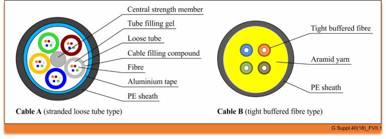
The world of optical communication is intricate, with different cable types designed for specific environments and applications. Today, we’re diving into the structure of two common types of optical fiber cables, as depicted in Figure below, and summarising the findings from an appendix that examined their performance.

cableA_B
#cable

Figure

Cable A: The Stranded Loose Tube Outdoor Cable

Cable A represents a quintessential outdoor cable, built to withstand the elements and the rigors of outdoor installation. The cross-section of this cable reveals a complex structure designed for durability and performance:

  • Central Strength Member: At its core, the cable has a central strength member that provides mechanical stability and ensures the cable can endure the tensions of installation.
  • Tube Filling Gel: Surrounding the central strength member are buffer tubes secured with a tube filling gel, which protects the fibers from moisture and physical stress.
  • Loose Tubes: These tubes hold the optical fibers loosely, allowing for expansion and contraction due to temperature changes without stressing the fibers themselves.
  • Fibers: Each tube houses six fibers, comprising various types specified by the ITU-T, including G.652.D, G.654.E, G.655.D, G.657.A1, G.657.A2, and G.657.B3. This array of fibers ensures compatibility with different transmission standards and conditions.
  • Aluminium Tape and PE Sheath: The aluminum tape provides a barrier against electromagnetic interference, while the polyethylene (PE) sheath offers physical protection and resistance to environmental factors.

The stranded loose tube design is particularly suited for long-distance outdoor applications, providing a robust solution for optical networks that span vast geographical areas.

Cable B: The Tight Buffered Indoor Cable

Switching our focus to indoor applications, Cable B is engineered for the unique demands of indoor environments:

  • Tight Buffered Fibers: Unlike Cable A, this indoor cable features four tight buffered fibers, which are more protected from physical damage and easier to handle during installation.
  • Aramid Yarn: Known for its strength and resistance to heat, aramid yarn is used to reinforce the cable, providing additional protection and tensile strength.
  • PE Sheath: Similar to Cable A, a PE sheath encloses the structure, offering a layer of defense against indoor environmental factors.

Cable B contains two ITU-T G.652.D fibers and two ITU-T G.657.B3 fibers, allowing for a blend of standard single-mode performance with the high bend-resistance characteristic of G.657.B3 fibers, making it ideal for complex indoor routing.

Conclusion

The intricate designs of optical fiber cables are tailored to their application environments. Cable A is optimized for outdoor use with a structure that guards against environmental challenges and mechanical stresses, while Cable B is designed for indoor use, where flexibility and ease of handling are paramount. By understanding the components and capabilities of these cables, network designers and installers can make informed decisions to ensure reliable and efficient optical communication systems.

Reference

https://www.itu.int/rec/T-REC-G.Sup40-201810-I/en

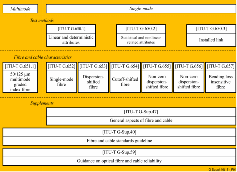
In the realm of telecommunications, the precision and reliability of optical fibers and cables are paramount. The International Telecommunication Union (ITU) plays a crucial role in this by providing a series of recommendations that serve as global standards. The ITU-T G.650.x and G.65x series of recommendations are especially significant for professionals in the field. In this article, we delve into these recommendations and their interrelationships, as illustrated in Figure 1 .

ITU-T G.650.x Series: Definitions and Test Methods

#opticalfiber

The ITU-T G.650.x series is foundational for understanding single-mode fibers and cables. ITU-T G.650.1 is the cornerstone, offering definitions and test methods for linear and deterministic parameters of single-mode fibers. This includes key measurements like attenuation and chromatic dispersion, which are critical for ensuring fiber performance over long distances.

Moving forward, ITU-T G.650.2 expands on the initial parameters by providing definitions and test methods for statistical and non-linear parameters. These are essential for predicting fiber behavior under varying signal powers and during different transmission phenomena.

For those involved in assessing installed fiber links, ITU-T G.650.3 offers valuable test methods. It’s tailored to the needs of field technicians and engineers who analyze the performance of installed single-mode fiber cable links, ensuring that they meet the necessary standards for data transmission.

ITU-T G.65x Series: Specifications for Fibers and Cables

The ITU-T G.65x series recommendations provide specifications for different types of optical fibers and cables. ITU-T G.651.1 targets the optical access network with specifications for 50/125 µm multimode fiber and cable, which are widely used in local area networks and data centers due to their ability to support high data rates over short distances.

The series then progresses through various single-mode fiber specifications:

  • ITU-T G.652: The standard single-mode fiber, suitable for a wide range of applications.
  • ITU-T G.653: Dispersion-shifted fibers optimized for minimizing chromatic dispersion.
  • ITU-T G.654: Features a cut-off shifted fiber, often used for submarine cable systems.
  • ITU-T G.655: Non-zero dispersion-shifted fibers, which are ideal for long-haul transmissions.
  • ITU-T G.656: Fibers designed for a broader range of wavelengths, expanding the capabilities of dense wavelength division multiplexing systems.
  • ITU-T G.657: Bending loss insensitive fibers, offering robust performance in tight bends and corners.

Historical Context and Current References

It’s noteworthy to mention that the multimode fiber test methods were initially described in ITU-T G.651. However, this recommendation was deleted in 2008, and now the test methods for multimode fibers are referenced in existing IEC documents. Professionals seeking current standards for multimode fiber testing should refer to these IEC documents for the latest guidelines.

Conclusion

The ITU-T recommendations play a critical role in the standardization and performance optimization of optical fibers and cables. By adhering to these standards, industry professionals can ensure compatibility, efficiency, and reliability in fiber optic networks. Whether you are a network designer, a field technician, or an optical fiber manufacturer, understanding these recommendations is crucial for maintaining the high standards expected in today’s telecommunication landscape.

Reference

https://www.itu.int/rec/T-REC-G/e