17 min read

400G ZR/ZR+ Coherent Optical Technology
Comprehensive Guide to Next-Generation Pluggable Coherent DWDM Transceivers for Data Center Interconnect and Metro Networks
Introduction
The explosive growth of cloud computing, streaming services, artificial intelligence, and data-intensive applications has created unprecedented demands on network infrastructure. Data centers must now transfer massive volumes of information across metropolitan and regional distances while maintaining low latency, high reliability, and cost-effectiveness. Traditional optical transport solutions, with their separate chassis-based transponders and complex deployment requirements, are increasingly unable to meet these challenges efficiently.
Enter 400G ZR and ZR+ coherent optical technology—a revolutionary approach that integrates advanced coherent detection capabilities directly into compact, pluggable transceiver modules. These innovations represent a fundamental shift in how networks are designed and operated, enabling network operators to plug coherent DWDM optics directly into routers and switches, eliminating the need for external optical transport equipment in many scenarios.
What is 400G ZR/ZR+?
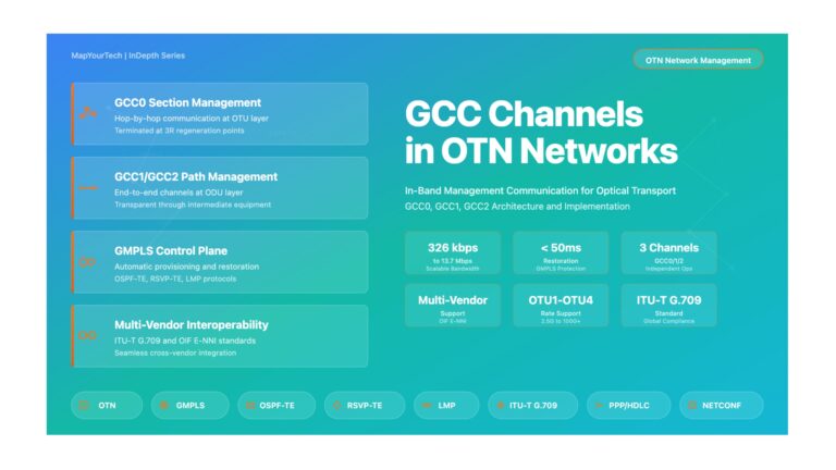
400G ZR is an industry-standard coherent optical interface defined by the Optical Internetworking Forum (OIF) that enables 400 Gbps transmission over Dense Wavelength Division Multiplexing (DWDM) networks in a compact QSFP-DD or OSFP form factor. The ZR+ variant, defined by the OpenZR+ Multi-Source Agreement (MSA), extends these capabilities with enhanced features including multiple modulation formats, higher output power, improved forward error correction, and support for flexible data rates from 100G to 400G.
Why 400G ZR/ZR+ Matters
The significance of 400G ZR/ZR+ technology extends across multiple dimensions of network architecture and operation. By packaging sophisticated coherent detection systems into pluggable modules no larger than traditional client-side optics, these transceivers enable a dramatic simplification of network infrastructure while simultaneously increasing capacity and reach.
Key Innovation: 400G ZR/ZR+ modules integrate Digital Signal Processors (DSPs), tunable lasers, coherent receivers, and advanced Forward Error Correction (FEC) into a single pluggable package consuming approximately 15 watts of power—a remarkable achievement considering that similar functionality previously required rack-mounted equipment consuming hundreds of watts.
Real-World Relevance and Industry Impact
The deployment of 400G coherent pluggables has fundamentally transformed network economics and design paradigms across multiple market segments. Hyperscale data center operators were early adopters, recognizing that integrating coherent optics directly into routers could eliminate entire layers of network equipment, reducing both capital expenditure and operational complexity. A single 400G ZR+ module can replace what previously required a separate transponder, wavelength multiplexer, and associated power and cooling infrastructure.
Service providers have embraced this technology for metro and regional networks, where the combination of compact form factor, standards-based interoperability, and impressive reach capabilities (up to 1,000+ km with ZR+ variants) enables more agile and cost-effective network architectures. Enterprise networks are beginning to leverage these optics for high-capacity campus interconnects and private DWDM networks, particularly as costs decline and deployment expertise grows.
Technology Applications
400G ZR/ZR+ technology serves a diverse range of network applications, each with specific requirements and optimization considerations. Data Center Interconnect (DCI) represents the primary use case, where facilities separated by 10 to 120 kilometers can establish high-capacity links without intermediate amplification. Metro and regional networks extend this capability to 500-1,000+ kilometers using amplified systems and advanced modulation formats. Edge computing architectures leverage these optics to connect distributed micro data centers with central facilities, while 5G backhaul and fronthaul networks benefit from the combination of high bandwidth and low latency.
Primary Application Scenarios
- Data Center Interconnect: Connecting facilities across metropolitan areas with 400G capacity on a single wavelength
- Metro Transport: Building high-capacity metro rings and mesh networks with flexible add/drop capabilities
- 5G Transport: Supporting massive capacity requirements for 5G mobile networks with low-latency connectivity
- Enterprise Networks: Enabling private DWDM networks for large campus environments and multi-site connectivity
- Cloud Interconnect: Providing high-bandwidth connections between cloud providers and customer locations
Key Concepts Preview
| Concept | Description | Significance |
|---|---|---|
| Coherent Detection | Advanced optical reception technique that recovers both amplitude and phase information | Enables longer reach and higher spectral efficiency than traditional intensity modulation |
| Form Factor Integration | Packaging complete coherent systems in QSFP-DD/OSFP modules | Eliminates external transponders, reduces footprint and power consumption |
| DWDM Capability | Tunable across C-band ITU grid channels | Supports multi-wavelength systems and flexible network architectures |
| Advanced FEC | Powerful error correction algorithms (CFEC, oFEC) | Extends reach by recovering signals from noisy channels |
| Multi-Rate Support | Flexible data rates from 100G to 400G (ZR+ only) | Optimizes capacity versus reach tradeoffs for different applications |
| Standards-Based Interoperability | OIF and MSA specifications ensure multi-vendor compatibility | Prevents vendor lock-in and enables competitive procurement |
Whether you are a network architect evaluating 400G coherent options, an engineer implementing these solutions, or a technical professional seeking to understand this transformative technology, this guide provides the comprehensive knowledge needed to make informed decisions and achieve successful deployments. The combination of theoretical foundation, practical guidance, interactive tools, and real-world examples ensures that readers at all levels—from those new to coherent optics to experienced professionals—will find valuable insights and actionable information.
Historical Context & Evolution
The journey to 400G ZR/ZR+ coherent pluggables represents decades of innovation in optical communications, digital signal processing, and semiconductor integration. Understanding this evolution provides essential context for appreciating the technical achievements these modules represent and the market forces that drove their development.
The Dawn of Coherent Optical Communications (1990s-2000s)
Coherent optical detection emerged as a research concept in the 1980s and 1990s, promising superior sensitivity and spectral efficiency compared to traditional intensity-modulation direct-detection (IM-DD) systems. However, early implementations faced significant challenges. Analog coherent systems required complex optical components and precise frequency stabilization, making them impractical for widespread deployment. The technology remained largely confined to research laboratories while the telecommunications industry relied on simpler, more robust direct-detection approaches.
The breakthrough came in the early 2000s with the advent of digital coherent technology. By combining coherent optical receivers with powerful Digital Signal Processors (DSPs), engineers could perform complex signal processing in the digital domain rather than the optical domain. This innovation enabled compensation for fiber impairments such as chromatic dispersion and polarization mode dispersion, previously major limitations on long-distance optical transmission. The first commercial 40G coherent systems appeared around 2008, followed quickly by 100G systems that became the workhorse of long-haul networks.
Coherent Optics in Chassis-Based Systems (2008-2016)
The initial generation of commercially successful coherent systems utilized large line cards in chassis-based platforms. These systems, while revolutionary in their performance, consumed significant power (often 100-300 watts per wavelength), occupied substantial space (multiple rack units), and required complex cooling systems. A typical 100G coherent transponder might consume an entire line card slot in a multi-terabit transport platform.
Despite their size and power requirements, these systems proved their value in long-haul and submarine networks where their superior reach and spectral efficiency justified the infrastructure investment. Network operators deployed them extensively in core networks, establishing coherent detection as the standard for high-capacity long-distance transmission. The success of these deployments demonstrated that the technology had matured sufficiently for production environments, setting the stage for further integration.
The CFP and CFP2 Form Factor Era (2013-2017)
As semiconductor technology advanced and DSP power efficiency improved, the industry achieved the first significant form factor reduction with CFP (C Form-factor Pluggable) modules. These devices, while still relatively large by today's standards, represented a major step toward integration. The CFP2-ACO (Analog Coherent Optics) variant separated the DSP function from the optical components, with the DSP remaining on the line card while the CFP2 module handled only the optical-to-analog and analog-to-optical conversions.
This architecture significantly reduced the module size and power consumption compared to full line-card solutions, making coherent optics practical for "pizza box" style transport platforms—1RU or 2RU systems that could deliver multi-terabit capacity in compact form factors. Cloud providers and hyperscale operators deployed these systems extensively for data center interconnect applications, demonstrating strong market demand for smaller, more power-efficient coherent solutions.
Key Technology Enablers
- Silicon Photonics: Integration of optical components on silicon substrates enabled dramatic size and cost reductions
- Advanced DSP Nodes: Migration from 28nm to 16nm and eventually 7nm process nodes reduced power consumption by orders of magnitude
- Integrated Tunable Lasers: Miniaturization of tunable laser assemblies (nano-ITLA) enabled C-band coverage in compact packages
- Thermal Management: Advanced cooling techniques allowed operation within QSFP-DD power budgets
The Hyperscale Data Center Catalyst (2016-2017)
The pivotal moment in the evolution toward modern coherent pluggables came when hyperscale operators identified a specific need: connecting data centers separated by 80-120 kilometers using 400G capacity on a single wavelength, with the optical modules plugging directly into routers rather than external transport equipment. This "IP over DWDM" architecture would eliminate entire layers of equipment, dramatically reducing capital costs, power consumption, and operational complexity.
These requirements seemed almost contradictory—400G coherent performance in a form factor similar to client-side optics (QSFP-DD or OSFP), consuming around 15 watts, with sufficient reach for amplified metro spans. Achieving this would require unprecedented levels of integration and power efficiency. However, the enormous purchasing power of hyperscale operators and the clear business case for the technology motivated industry-wide collaboration to make it reality.
OIF 400ZR Standardization (2016-2020)
In late 2016, the Optical Internetworking Forum (OIF) initiated the 400ZR project with the ambitious goal of standardizing interoperable coherent interfaces in QSFP-DD and OSFP form factors. The OIF brought together network operators, equipment manufacturers, DSP vendors, and optical component suppliers to define a baseline specification that would meet the data center interconnect use case while ensuring multi-vendor interoperability.
The OIF 400ZR Implementation Agreement, completed in March 2020, specified dual-polarization 16QAM modulation, CFEC (Concatenated Forward Error Correction), and operation on 75 GHz grid spacing. Target performance included 120 km reach over amplified links with a required OSNR of approximately 26 dB. The specification carefully balanced performance requirements against power consumption constraints, accepting some limitations in reach and functionality to achieve the 15W power budget and ensure manufacturability.
| Year | Milestone | Impact |
|---|---|---|
| 2008 | First commercial 40G/100G coherent systems | Established digital coherent as viable technology for long-haul networks |
| 2013-2015 | CFP/CFP2 coherent modules introduced | Enabled compact transport platforms and reduced power consumption |
| 2016 | OIF 400ZR project initiated | Industry alignment on pluggable coherent standard for DCI applications |
| 2020 | OIF 400ZR Implementation Agreement published | Established baseline interoperable specification for 400G coherent pluggables |
| 2020-2021 | OpenZR+ MSA formed and specification released | Extended capabilities beyond 400ZR for metro and regional applications |
| 2021-2023 | Mass production and deployment of 400ZR/ZR+ modules | Widespread adoption across data center, metro, and enterprise networks |
| 2024-2025 | 800G ZR/ZR+ standards development and early deployments | Next generation doubling capacity while maintaining similar form factors |
OpenZR+ and Extended Capabilities (2020-2021)
While OIF 400ZR successfully addressed the data center interconnect use case, network operators and equipment vendors recognized opportunities to extend coherent pluggable capabilities for metro and regional networks. The OpenZR+ Multi-Source Agreement emerged to combine elements from OIF 400ZR and Open ROADM specifications, creating a more feature-rich standard while maintaining the Ethernet-centric approach and compact form factors.
OpenZR+ added several critical enhancements: more powerful oFEC (OpenFEC) forward error correction from the Open ROADM standard, extending reach capabilities significantly; support for multiple modulation formats (QPSK, 8QAM, 16QAM) enabling optimization of capacity versus reach; flexible data rates from 100G to 400G allowing multiplexing of lower-rate clients; and higher output power options supporting longer unamplified spans and legacy network integration.
These enhancements extended the practical reach of coherent pluggables from 120 km to over 1,000 km in optimized configurations, opening new applications in metro rings, regional networks, and even some long-haul scenarios. The OpenZR+ specification also defined "A" and "B" configurations addressing colored (wavelength-selective) and colorless (broadcast-and-select) network add/drop structures, ensuring compatibility with various network architectures.
Commercial Deployment and Market Evolution (2021-Present)
The period from 2021 to present has seen explosive growth in 400G coherent pluggable deployments. Multiple vendors brought interoperable 400ZR and ZR+ modules to market, with successful interoperability testing demonstrating the viability of multi-vendor environments. Hyperscale operators deployed these optics by the thousands for data center interconnects, validating both the technical performance and business case.
Service providers began incorporating 400G coherent pluggables into metro and regional networks, leveraging the OpenZR+ capabilities for applications beyond simple point-to-point DCI. Enterprise adoption accelerated as prices declined and deployment expertise grew, with large organizations using these optics for private DWDM networks connecting campus facilities. The technology proved itself in diverse environments, from pristine hyperscale networks to challenging brownfield deployments with legacy fiber plant and equipment.
Current State and Future Outlook (2024-2025)
As of 2025, 400G coherent pluggables have achieved mainstream status, with mature supply chains, proven reliability, and widespread deployment expertise. The technology continues evolving, with several key trends emerging. The OIF published the 800ZR standard in October 2024, specifying next-generation coherent pluggables that double capacity to 800G while maintaining similar form factors and power budgets. This achievement, made possible by advanced 5nm DSP nodes and further silicon photonics integration, promises to sustain the coherent pluggable revolution for years to come.
The OpenZR+ MSA released guidelines for 800G OpenZR+ in early 2025, extending the enhanced capabilities of the ZR+ approach to the higher speed tier. Industry attention is also turning to 1.6T coherent optics, though technical challenges around power consumption and thermal management remain significant. Parallel developments include integration of coherent optics into switch ASICs (co-packaged optics), potentially enabling even greater integration and efficiency.
Market Projection: Industry analysts project that coherent pluggables will account for the majority of new data center interconnect deployments by 2027, with shipments exceeding 5 million units annually. The technology is also expected to penetrate deeper into metro networks and enterprise environments as costs continue declining and operational familiarity increases.
The evolution from room-sized coherent systems to pluggable modules smaller than a deck of cards represents one of the most remarkable integration achievements in communications history. This journey required breakthroughs in multiple disciplines—digital signal processing, silicon photonics, thermal management, and standards development—demonstrating the power of focused industry collaboration addressing clearly defined market needs. The success of 400G ZR/ZR+ has established a template for future optical transceiver development, where performance, power efficiency, and interoperability advance in concert rather than as competing priorities.
Core Concepts & Fundamentals
Understanding 400G ZR/ZR+ technology requires grasping several fundamental concepts that distinguish coherent detection from traditional optical transmission methods. This section builds a comprehensive foundation, explaining the principles that enable these remarkable devices to achieve extraordinary performance in compact, power-efficient packages.
Coherent Detection: The Foundation
Coherent optical detection represents a fundamentally different approach to recovering information from optical signals compared to traditional intensity-modulation direct-detection (IM-DD) systems. In IM-DD systems, information is encoded solely in the intensity (power) of the optical signal, and a simple photodiode recovers this information by converting optical power variations directly into electrical current. While simple and cost-effective, this approach discards phase information and provides limited sensitivity and spectral efficiency.
Coherent detection, by contrast, preserves and recovers both the amplitude and phase of the optical electric field. This is achieved by mixing the incoming signal with a local oscillator—a highly stable, tunable laser at the receiver—in an optical hybrid component. The mixing process, analogous to superheterodyne radio receivers, translates the optical signal to an intermediate frequency or baseband, where sophisticated electronics can digitize and process it.
Key Advantages of Coherent Detection
- Superior Sensitivity: Coherent receivers can approach the quantum shot-noise limit, achieving receiver sensitivities 10-15 dB better than direct detection
- Phase Information Recovery: Access to both amplitude and phase enables advanced modulation formats encoding multiple bits per symbol
- Digital Compensation: DSP can compensate for fiber impairments (dispersion, polarization effects) that would otherwise limit transmission distance
- Wavelength Selectivity: The local oscillator acts as an extremely narrow optical filter, enabling tight channel spacing in DWDM systems
Dual-Polarization Transmission
Optical fiber supports two orthogonal polarization states that can carry independent information streams simultaneously on the same wavelength. 400G ZR/ZR+ transceivers exploit this property using dual-polarization transmission, effectively doubling the information capacity without increasing the optical bandwidth or symbol rate.
At the transmitter, the data stream is split into two independent tributaries that modulate two orthogonal polarization states (typically designated X-polarization and Y-polarization). These polarizations propagate through the fiber, though they mix and rotate due to fiber birefringence and environmental effects. At the coherent receiver, polarization beam splitters separate the received signal into two polarization components, which are independently mixed with the local oscillator and digitized.
The digital signal processor then performs polarization demultiplexing, using adaptive algorithms to separate the transmitted X and Y tributaries from the scrambled received polarizations. This process happens continuously and automatically, tracking changes in polarization state with microsecond timescales. The ability to separate arbitrarily scrambled polarizations in the digital domain is one of the key enablers of modern coherent systems.
Advanced Modulation Formats
While traditional optical systems modulate only the intensity of light, coherent systems can independently modulate both amplitude and phase, enabling sophisticated multilevel modulation formats that encode multiple bits per transmitted symbol. This spectral efficiency advantage is crucial for achieving high data rates within limited optical bandwidth.
QPSK (Quadrature Phase Shift Keying)
QPSK modulation uses four distinct phase states (0°, 90°, 180°, 270°) to encode two bits per symbol per polarization. In dual-polarization systems (DP-QPSK), this yields four bits per symbol period across both polarizations. QPSK provides excellent tolerance to optical noise and nonlinear impairments, making it the preferred choice for long-reach applications where the optical signal-to-noise ratio may be degraded by multiple amplifiers or long fiber spans.
The OpenZR+ specification supports DP-QPSK for 100G and 200G modes, where reach is prioritized over capacity. A 200G link using DP-QPSK operates at approximately 32-33 GBaud symbol rate, achieving impressive reach capabilities of 1,000+ km in optimized configurations with powerful forward error correction.
8QAM (8-ary Quadrature Amplitude Modulation)
8QAM uses eight constellation points combining both amplitude and phase modulation, encoding three bits per symbol per polarization (six bits per symbol for DP-8QAM). This format represents a middle ground between QPSK's robustness and 16QAM's spectral efficiency. The OpenZR+ specification supports DP-8QAM for 300G operation, providing a balanced compromise between capacity and reach suitable for regional network applications (typically 500-800 km depending on fiber plant and amplification strategy).
16QAM (16-ary Quadrature Amplitude Modulation)
16QAM employs sixteen constellation points arranged in a square grid, with both amplitude and phase varying between symbols. Each symbol carries four bits per polarization (eight bits per symbol for DP-16QAM), delivering high spectral efficiency. OIF 400ZR and OpenZR+ 400G modes use DP-16QAM at approximately 60 GBaud, achieving 400G data rates in relatively compact optical bandwidth.
However, 16QAM's increased spectral efficiency comes at the cost of reduced tolerance to optical noise and fiber nonlinearities. The constellation points are more densely packed, requiring higher optical signal-to-noise ratios to reliably distinguish between symbols. This tradeoff limits 16QAM to relatively short distances (120 km for 400ZR, potentially 300-400 km for 400ZR+ depending on configuration) compared to lower-order modulation formats.
| Modulation | Bits per Symbol (Dual-Pol) | Capacity at 60 GBaud | OSNR Requirement | Typical Reach |
|---|---|---|---|---|
| DP-QPSK | 4 bits | ~200G | ~13 dB | 1,000+ km |
| DP-8QAM | 6 bits | ~300G | ~18 dB | 500-800 km |
| DP-16QAM | 8 bits | ~400G | ~24-26 dB | 120-400 km |
Forward Error Correction (FEC)
Forward Error Correction is essential for reliable optical communication, adding redundancy that enables the receiver to detect and correct bit errors introduced by noise, dispersion, and other impairments. The choice of FEC algorithm significantly impacts both reach capability and latency, representing a key differentiator between 400ZR and OpenZR+ specifications.
CFEC (Concatenated FEC)
The OIF 400ZR standard employs CFEC, a relatively lightweight error correction scheme that provides moderate coding gain (approximately 10.5 dB) with low latency (<10 microseconds). CFEC uses a concatenation of Reed-Solomon codes, offering good performance for the target DCI application while maintaining power efficiency. The algorithm can correct bit error rates up to approximately 2×10⁻² pre-FEC, sufficient for 120 km amplified spans with moderate OSNR requirements.
oFEC (OpenFEC)
OpenZR+ transceivers implement oFEC (also called RS(544,514) FEC), a more powerful error correction algorithm derived from the Open ROADM specification. oFEC provides approximately 12-13 dB of coding gain, enabling correction of higher pre-FEC bit error rates (up to approximately 1×10⁻¹) and significantly extending reach capabilities. This additional coding gain is crucial for metro and regional applications where signals traverse multiple amplifier stages and accumulate substantial noise.
The enhanced performance of oFEC comes with increased computational complexity and slightly higher latency (typically 15-20 microseconds), though these tradeoffs are acceptable for applications prioritizing reach over absolute minimum latency. The 2-3 dB OSNR advantage provided by oFEC can translate to several hundred kilometers of additional reach or alternatively, reduced requirements for optical amplifier performance and spacing.
Digital Signal Processing Architecture
The Digital Signal Processor represents the computational heart of coherent transceivers, performing complex real-time signal processing at rates of tens of gigasamples per second. Understanding DSP functions illuminates how these devices achieve their remarkable performance characteristics.
Transmit-Side DSP Functions
On the transmit side, the DSP receives client data (400GbE frames for 400ZR, or multiplexed 100GE/200GE/400GE for OpenZR+), applies FEC encoding, maps the coded bits to modulation symbols, performs pulse shaping to optimize spectral characteristics, and generates drive signals for the optical modulator. Pre-compensation for known channel impairments (chromatic dispersion, for example) can also be applied at the transmitter, reducing receiver complexity.
Receive-Side DSP Functions
The receive-side DSP workload is significantly more demanding. After analog-to-digital conversion of the four photodiode outputs (two polarizations, in-phase and quadrature for each), the DSP performs: timing recovery to synchronize symbol clock extraction; chromatic dispersion compensation, correcting hundreds or thousands of picoseconds per nanometer of accumulated dispersion; polarization demultiplexing using adaptive filters to separate the transmitted polarization tributaries; carrier phase recovery to track and remove phase noise from transmitter and local oscillator lasers; and finally, FEC decoding to correct bit errors.
Many of these functions use adaptive algorithms that continuously adjust to changing channel conditions. Polarization demultiplexing, for instance, must track polarization state changes occurring on millisecond timescales. Carrier phase recovery accommodates laser linewidth and phase noise. This adaptive processing enables coherent transceivers to operate reliably over diverse fiber plants and network configurations without manual tuning or adjustment.
DSP Advancement: The evolution from 28nm to 16nm and then 7nm semiconductor process nodes reduced power consumption of coherent DSPs by more than 10× while simultaneously increasing processing capability. This scaling, following Moore's Law trajectories, was essential for achieving the 15W power budget targets of pluggable coherent modules.
DWDM Grid and Channel Spacing
Dense Wavelength Division Multiplexing enables multiple optical channels to coexist on the same fiber by assigning each to a specific wavelength on a standardized frequency grid. The ITU-T G.694.1 standard defines the DWDM grid, with channels spaced at 100 GHz, 75 GHz, 50 GHz, or narrower intervals across the C-band (approximately 1530-1565 nm, corresponding to 191.0-196.1 THz).
OIF 400ZR specifies operation on 75 GHz grid spacing, accommodating the approximately 60 GHz optical bandwidth of a 60 GBaud DP-16QAM signal with modest guardbands. This spacing enables 64 channels across the C-band, providing 25.6 Tbps aggregate capacity on a single fiber pair. OpenZR+ supports flexible grid spacing of 50/75/100 GHz, with the specific choice depending on modulation format, symbol rate, and network architecture requirements.
All 400G coherent transceivers incorporate tunable lasers covering the full C-band, eliminating the need for wavelength-specific inventory. A single SKU can be deployed at any DWDM channel, with software configuration selecting the desired frequency. This tunability dramatically simplifies sparing, reduces inventory costs, and enables rapid wavelength reassignment for network optimization or restoration scenarios.
Optical Signal-to-Noise Ratio (OSNR)
OSNR quantifies the ratio of signal power to noise power in a defined optical bandwidth (typically 0.1 nm or 12.5 GHz), representing the fundamental metric for optical link quality in DWDM systems. Coherent receivers require specific minimum OSNR values for each modulation format to achieve target post-FEC bit error rates (typically below 10⁻¹⁵ for error-free operation).
Required OSNR (rOSNR) values serve as the primary specification for coherent transceiver sensitivity. OIF 400ZR, using DP-16QAM and CFEC, specifies rOSNR of approximately 26 dB (0.1 nm). OpenZR+ 400G with oFEC achieves the same data rate at approximately 24 dB rOSNR, reflecting the 2 dB advantage of the more powerful FEC algorithm. Lower data rate modes using QPSK or 8QAM achieve dramatically lower rOSNR requirements—potentially 13-14 dB for 100G QPSK—enabling much longer reach.
OSNR degrades as optical signals traverse amplified systems, with each amplifier adding amplified spontaneous emission (ASE) noise. Link engineering involves calculating cumulative OSNR degradation and ensuring adequate margin at the receiver. Typical design targets include 2-3 dB OSNR margin above the required value to accommodate aging, repairs, and variations in component performance.
Form Factor and Power Considerations
The compact form factors of 400G coherent pluggables—primarily QSFP-DD and OSFP—represent remarkable packaging achievements. QSFP-DD modules measure approximately 72mm length × 18mm width × 8.5mm height, only marginally larger than client-side QSFP28 optics used for shorter-reach applications. Within this volume, engineers must fit tunable lasers, optical modulators, coherent receivers, high-speed analog-to-digital converters, sophisticated DSPs, and all associated power management and thermal control systems.
Power consumption targets of approximately 15 watts (12W for some implementations) require extreme efficiency at every level. The 7nm DSP nodes mentioned earlier are essential, as are efficient optical components. Silicon photonics technology has proven crucial, enabling integration of modulators, hybrid couplers, and other optical functions on compact, manufacturable silicon dies. Advanced thermal management, including vapor chambers and optimized airflow paths, ensures reliable operation even in demanding high-density router environments.
The achievement of these specifications represents years of collaborative optimization across the supply chain—from semiconductor fabs producing leading-edge DSP nodes, to specialty manufacturers of tunable lasers and silicon photonics components, to module integrators balancing electrical, optical, and thermal design constraints within extraordinarily tight spatial and power budgets.
Technical Architecture & Components
The architecture of 400G ZR/ZR+ transceivers represents a sophisticated integration of optical, analog, and digital subsystems within remarkably compact form factors. Understanding the component-level architecture and signal flow provides insight into how these modules achieve their impressive performance specifications.
System-Level Architecture
A 400G coherent pluggable transceiver can be conceptually divided into several major functional blocks: the host electrical interface connecting to the router or switch, the transmit path converting electrical signals to modulated optical output, the receive path processing incoming optical signals back to electrical form, the tunable laser serving as both transmit source and local oscillator, the Digital Signal Processor coordinating all signal processing functions, and power management and control systems ensuring reliable operation.
Transmit Path Architecture
The transmit path begins with client data arriving through high-speed electrical SerDes interfaces—typically 8 lanes of 56 Gbps PAM4 for 400G operation, conforming to IEEE 400GAUI-8 specifications. The DSP receives this data, performs FEC encoding, maps coded bits to modulation symbols, and generates drive signals for the optical modulator.
The I/Q modulator comprises nested Mach-Zehnder structures fabricated in silicon photonics or lithium niobate. Separate drive signals control in-phase (I) and quadrature (Q) components for each polarization, enabling independent modulation of amplitude and phase. A polarization beam combiner merges the X and Y polarization tributaries, and the resulting dual-polarization modulated signal couples into the output fiber through a wavelength-tunable transmit laser.
Receive Path Architecture
The receive path processes incoming optical signals through a polarization-diverse coherent receiver. The signal first passes through a polarization beam splitter separating X and Y polarizations. Each polarization mixes with the local oscillator (derived from the same tunable laser used for transmit, ensuring wavelength matching) in a 90-degree optical hybrid.
The optical hybrid generates four outputs for each polarization: I-positive, I-negative, Q-positive, and Q-negative. Eight balanced photodetectors (four per polarization) convert these optical signals to electrical currents, which transimpedance amplifiers convert to voltages. High-speed analog-to-digital converters sampling at twice the symbol rate (approximately 120 Gsps for 60 GBaud systems) digitize the signals for DSP processing.
Key Components Deep Dive
Digital Signal Processor (DSP)
Modern coherent DSPs integrate tens of billions of transistors fabricated in advanced nodes (7nm or 5nm), operating at clock speeds exceeding 1 GHz while consuming only 5-8 watts. The DSP architecture typically employs specialized hardware accelerators for computationally intensive functions like FEC decoding and adaptive equalization, alongside programmable processors for control and monitoring functions.
Advanced power management techniques including dynamic voltage and frequency scaling, clock gating, and power domain isolation ensure the DSP meets strict power budgets. The DSP also manages module initialization, wavelength tuning, temperature monitoring, and reporting of performance metrics through the CMIS (Common Management Interface Specification) standardized management interface.
Tunable Laser (nano-ITLA)
The tunable laser must cover the entire C-band (approximately 4-5 THz tuning range) with high spectral purity, narrow linewidth (typically <100 kHz), and stable output power across temperature variations. Modern implementations use micro-electro-mechanical systems (MEMS) or thermal tuning of integrated gratings to achieve wavelength selection, packaged in "nano-ITLA" (Integrable Tunable Laser Assembly) form factors measuring only a few millimeters.
The laser output splits into two paths: the transmit path feeding the optical modulator, and a small portion tapped for use as the local oscillator in the coherent receiver. This architecture, called "self-homodyne" detection, ensures perfect wavelength matching between transmitter and local oscillator, simplifying receiver DSP processing compared to "intradyne" systems using separate lasers.
Silicon Photonics Integration
Silicon photonics technology enables monolithic integration of multiple optical functions—modulators, couplers, multiplexers, filters—on a single silicon die using semiconductor fabrication processes. This integration dramatically reduces size, cost, and power consumption compared to discrete optical component assemblies.
A typical coherent transceiver might incorporate separate silicon photonics dies for the transmitter (including I/Q modulators and polarization beam combiner) and receiver (including polarization beam splitters, 90-degree hybrids, and photodetectors), co-packaged with the DSP and tunable laser. The precision of semiconductor lithography ensures consistent performance across manufacturing volumes, critical for achieving interoperability specifications.
| Component | Function | Key Technologies | Power Consumption |
|---|---|---|---|
| DSP | Signal processing, FEC, modulation/demodulation | 7nm/5nm CMOS, specialized accelerators | 5-8W |
| Tunable Laser | Optical source and local oscillator | MEMS or thermal tuning, narrow linewidth | 2-3W |
| TX Modulator | Encode data onto optical carrier | Silicon photonics I/Q modulator | 1-2W |
| RX Hybrid & PDs | Coherent detection | Silicon photonics, balanced photodetectors | 2-3W |
| SerDes & Analog | Host interface, ADCs/DACs | High-speed mixed-signal circuits | 2-3W |
Standards and Interoperability
Achieving multi-vendor interoperability requires precise specification of both optical and digital layer parameters. The OIF 400ZR Implementation Agreement specifies line-side optical characteristics (wavelength, power, OSNR, dispersion tolerance), FEC code structure, frame formats, and management interfaces. OpenZR+ extends these specifications with additional operating modes and enhanced optical performance parameters.
The Common Management Interface Specification (CMIS) defines standardized register maps and protocols for module configuration and monitoring. Through CMIS, host systems can read module capabilities, configure operating modes, tune wavelength, monitor temperature and optical power, and retrieve performance metrics—all using a vendor-neutral interface ensuring compatibility across different router platforms.
Mathematical Models & Formulas
Quantitative analysis of 400G ZR/ZR+ systems requires understanding the mathematical relationships governing optical transmission, signal-to-noise ratios, modulation performance, and system capacity. These formulas provide the foundation for link engineering and performance prediction.
Link Budget Calculation
Optical Power Budget
The fundamental link budget equation:
Where:
- P_RX: Received optical power at coherent receiver input (dBm)
- P_TX: Transmit optical power from ZR/ZR+ module (typically 0 to +4 dBm)
- Loss_fiber: Fiber attenuation (typically 0.2 dB/km for standard SMF)
- Loss_connectors: Connector insertion loss (typically 0.5 dB each)
- Loss_splices: Splice loss (typically 0.1 dB each)
- Gain_amplifiers: Optical amplifier gain (if present)
- Margin: System margin for aging, repairs (typically 2-3 dB)
Example calculation for 100 km link:
OSNR Requirements and Degradation
OSNR Calculation for Amplified Systems
Required OSNR at receiver:
OSNR degradation in amplifier cascade:
Single amplifier OSN contribution:
Where:
- SNR_required: Signal-to-noise ratio needed for target BER (varies by modulation)
- B_ref: Reference bandwidth for OSNR measurement (typically 12.5 GHz)
- B_signal: Signal bandwidth
- NF: Amplifier noise figure (typically 4.5-6 dB)
- h: Planck's constant (6.626×10⁻³⁴ J·s)
- f: Optical frequency (~194 THz for C-band)
Spectral Efficiency and Capacity
Spectral Efficiency Calculation
Spectral efficiency (bits/s/Hz):
For dual-polarization M-QAM:
Where:
- M: Constellation size (4 for QPSK, 8 for 8QAM, 16 for 16QAM)
- R_FEC: FEC code rate (information bits / total bits)
- Factor of 2: Accounts for dual polarization
Example for 400ZR (DP-16QAM with CFEC):
Chromatic Dispersion Tolerance
Dispersion Accumulation
Total chromatic dispersion:
For standard single-mode fiber (G.652):
Where:
- D_fiber: Fiber dispersion parameter (~17 ps/(nm·km) for G.652 at 1550 nm)
- L: Fiber length (km)
- Δλ: Source spectral width (nm)
Coherent systems specification:
400ZR/ZR+ modules typically specify dispersion tolerance of ±2,400 ps/nm or more, corresponding to approximately 140 km of standard fiber—sufficient for most metro applications without external dispersion compensation.
FEC Performance Metrics
FEC Coding Gain
Net coding gain (NCG):
FEC threshold improvement:
Typical values:
- CFEC (400ZR): ~10.5 dB NCG, corrects BER up to 2×10⁻²
- oFEC (OpenZR+): ~12-13 dB NCG, corrects BER up to 1×10⁻¹
Post-FEC BER target:
System Capacity Scaling
Total System Capacity
For DWDM system with N channels:
Maximum channel count:
Example for C-band with 400ZR (75 GHz spacing):
Practical Engineering Considerations
Real-world link engineering requires accounting for additional factors beyond these idealized formulas: nonlinear impairments including self-phase modulation and cross-phase modulation in high-power DWDM systems; polarization-dependent loss creating power imbalances between polarization tributaries; reflections from connectors and splices causing multi-path interference; and temperature-dependent variations in fiber characteristics and component performance. Modern coherent DSPs compensate for many of these effects, but margin allocation in link budgets should account for worst-case scenarios.
Types, Variations & Classifications
The 400G coherent pluggable ecosystem encompasses multiple variants optimized for different applications, network architectures, and performance requirements. Understanding these classifications helps network architects select appropriate solutions for specific deployment scenarios.
Primary Standards-Based Classifications
OIF 400ZR
OIF 400ZR represents the baseline industry standard for 400G coherent pluggables, optimized specifically for data center interconnect applications. This specification emphasizes interoperability, power efficiency, and cost-effectiveness within its target reach envelope of 80-120 km. The standard mandates DP-16QAM modulation at approximately 60 GBaud symbol rate, CFEC forward error correction, and operation on 75 GHz DWDM grid spacing.
400ZR modules typically provide transmit power around 0 dBm and require received OSNR of approximately 26 dB (0.1 nm reference bandwidth) for error-free operation. The specification supports single-span amplified links or shorter unamplified point-to-point connections. Client interface is 400GbE only, using 8×56 Gbps PAM4 electrical lanes. Power consumption targets 15W or less, with many implementations achieving 12-13W.
400ZR Key Characteristics
- Data Rate: 400 Gbps (fixed)
- Modulation: DP-16QAM (fixed)
- FEC: CFEC (~10.5 dB gain)
- Reach: Up to 120 km amplified, ~40 km unamplified
- TX Power: Typically 0 dBm
- rOSNR: ~26 dB
- Grid Spacing: 75 GHz
- Interoperability: Full multi-vendor per OIF spec
OpenZR+ 400G
OpenZR+ extends 400ZR capabilities with features targeting metro and regional network applications. The most significant enhancement is oFEC (OpenFEC), providing 2-3 dB better OSNR performance than CFEC and enabling significantly longer reach—potentially 500-1,000+ km depending on configuration. OpenZR+ also supports multiple modulation formats (QPSK, 8QAM, 16QAM) and flexible data rates from 100G to 400G.
The OpenZR+ specification defines multiple operating modes: 400ZR+ mode uses DP-16QAM with oFEC for ~400 km reach; 300ZR+ mode uses DP-8QAM with oFEC for ~600-800 km reach; 200ZR+ mode uses DP-QPSK with oFEC for 1,000+ km reach; and 100ZR+ mode uses DP-QPSK with oFEC for ultra-long reach applications. Client interfaces support multiplexing of 100GE, 200GE, and 400GE streams.
OpenZR+ also addresses network add/drop architecture requirements with "A" (colored) and "B" (colorless) configurations. Colored configurations assume wavelength-selective filtering at add/drop points, enabling relaxed specifications for out-of-band emissions. Colorless configurations support broadcast-and-select architectures but require tighter specifications to minimize crosstalk penalties.
Vendor-Specific Variants
High-Power Variants (ZR-HP, ZR-HT)
Several vendors offer high-power variants of both 400ZR and OpenZR+ transceivers, typically providing +2 to +4 dBm transmit power compared to standard 0 dBm modules. These higher-power options extend unamplified reach significantly—potentially 80-100 km compared to 40-50 km for standard modules—and improve compatibility with legacy DWDM infrastructure designed for higher optical power levels.
High-power modules consume additional power (typically 16-18W total) and generate more heat, requiring careful thermal management in dense deployments. They prove particularly valuable for brownfield applications integrating coherent pluggables into existing transport networks, and for long-reach campus or enterprise interconnects where amplifiers are impractical.
Extended Temperature Range Modules
While standard coherent pluggables specify 0-70°C operating temperature, extended temperature variants support -5 to +75°C or -40 to +85°C, accommodating outdoor cabinets, harsh industrial environments, and temperature-uncontrolled telecom huts. These rugged modules incorporate enhanced thermal design and component qualification but typically maintain standard optical performance specifications.
Form Factor Variations
QSFP-DD vs. OSFP
The majority of 400G coherent modules use QSFP-DD form factor (18mm width), which offers the advantages of maximizing port density on router faceplates and compatibility with existing QSFP-DD ports for client optics. OSFP modules (22.58mm width) provide additional internal volume enabling slightly better thermal performance and potentially supporting future higher-power configurations (800G and beyond) but sacrifice some density.
Market adoption has strongly favored QSFP-DD, driven by router and switch vendors' preference for consistent port width across client and coherent optics. However, OSFP maintains relevance for platforms specifically optimized for this form factor and may see increased adoption as 800G modules push thermal limits of the smaller QSFP-DD package.
| Type | Standard/Variant | Data Rates | Modulation | Typical Reach | Primary Applications |
|---|---|---|---|---|---|
| 400ZR | OIF Standard | 400G only | DP-16QAM | Up to 120 km | DCI, metro P2P |
| 400ZR-HP | High Power | 400G only | DP-16QAM | Up to 100 km unamplified | Long campus, legacy integration |
| OpenZR+ 400G | OpenZR+ MSA | 400G | DP-16QAM | Up to 400 km | Metro, regional |
| OpenZR+ 300G | OpenZR+ MSA | 300G | DP-8QAM | Up to 800 km | Regional, some long-haul |
| OpenZR+ 200G | OpenZR+ MSA | 200G | DP-QPSK | 1,000+ km | Long-haul, submarine |
| OpenZR+ 100G | OpenZR+ MSA | 100G | DP-QPSK | 1,500+ km | Ultra-long-haul |
Selection Decision Matrix
Choosing the appropriate 400G coherent variant requires evaluating multiple factors. Distance is primary—for DCI applications under 120 km, standard 400ZR offers excellent cost-effectiveness and interoperability. Metro applications from 120-400 km benefit from OpenZR+ 400G mode with its oFEC advantage. Regional networks exceeding 400 km should consider OpenZR+ 300G or 200G modes, accepting the capacity reduction for reach extension.
Network architecture influences selection—colorless add/drop requires "B" configuration OpenZR+ modules, while colored architectures can use more cost-effective "A" configuration. Interoperability requirements favor standards-compliant 400ZR or OpenZR+ over proprietary enhanced variants. Power budget constraints may necessitate standard modules, while legacy integration might require high-power options.
Future capacity growth plans should inform decisions—deploying OpenZR+ modules even for initial 400ZR-suitable applications provides flexibility to later reconfigure for longer reach or different data rates without hardware changes. However, the additional cost of OpenZR+ capabilities versus 400ZR must be justified by actual requirements rather than speculative future needs.
Interactive Simulators
Explore the performance characteristics of 400G ZR/ZR+ systems through these interactive simulators. Adjust parameters in real-time to understand the tradeoffs between capacity, reach, and signal quality.
Simulator 1: OSNR & Reach Performance
Simulator 2: Modulation Format Comparison
Simulator 3: Link Budget Calculator
Simulator 4: DWDM System Capacity Planner
Practical Applications & Case Studies
Real-world deployment of 400G ZR/ZR+ transceivers requires understanding not just technical specifications but also practical implementation challenges, optimization strategies, and operational best practices. This section presents detailed case studies from diverse network environments alongside troubleshooting guidance and recommendations drawn from actual deployments.
Case Study 1: Hyperscale Data Center Interconnect
Metro DCI Network Transformation
Challenge
A major cloud services provider needed to interconnect eight data centers distributed across a metropolitan area spanning 80 km diameter. The existing solution used separate transport equipment with CFP2 coherent modules, consuming significant rack space, power, and requiring complex management of router and transport layers. Traffic growth projections indicated the need to scale from 100G to 400G per wavelength within 18 months while reducing operational complexity and capital expenditure.
Solution Approach
The operator deployed OIF 400ZR QSFP-DD transceivers directly into router ports, implementing an IP-over-DWDM architecture that eliminated external transport equipment. The solution utilized 48-wavelength CWDM/DWDM passive multiplexers at each site, with all links under 120 km suitable for single-span amplified or unamplified operation. Wavelength assignment followed a carefully planned grid with 75 GHz spacing to maximize C-band capacity.
Implementation Details
- Link Design: Point-to-point connections ranging from 25 km to 115 km using standard G.652 fiber
- Amplification Strategy: Erbium-doped fiber amplifiers (EDFAs) at mid-span for links exceeding 50 km
- Power Budget: 0 dBm transmit power, with received power ranging from -8 dBm (short links) to -22 dBm (long links)
- Monitoring: CMIS-based telemetry integrated with network management system for real-time performance tracking
- Protection: Dual fiber paths with automatic failover for critical inter-DC connections
Results and Benefits
- Capacity Increase: 4× capacity improvement (100G to 400G per wavelength) supporting traffic growth projections for 3+ years
- Space Reduction: 60% reduction in rack space compared to previous transport equipment solution
- Power Savings: 45% lower power consumption through elimination of transport chassis and associated cooling
- OpEx Reduction: Simplified operations with single management plane for routing and transport functions
- CapEx Savings: 35% cost reduction through elimination of transport equipment and reduction in support systems
- Deployment Speed: Average installation time reduced from 4 hours to 45 minutes per link
Lessons Learned
Initial deployment revealed the importance of thorough fiber plant characterization—several links required additional cleaning or connector replacement to achieve target OSNR. Implementing automated wavelength tuning and power level optimization during installation significantly reduced commissioning time. The operator established standardized power level targets and OSNR thresholds that simplified troubleshooting across the entire network. Multi-vendor interoperability testing prior to procurement ensured seamless integration despite using transceivers from three different suppliers.
Case Study 2: Regional Service Provider Metro Ring
Metro Ring Capacity Upgrade
Challenge
A regional telecommunications provider operated a metro ring spanning 320 km connecting six cities with legacy 100G DWDM equipment approaching end-of-life. The network required capacity expansion to support 5G backhaul, enterprise services growth, and wholesale bandwidth services. The ring architecture included reconfigurable optical add-drop multiplexers (ROADMs) at each node, with some segments traversing challenging fiber plant including older G.652 fiber with elevated polarization mode dispersion.
Solution Approach
The provider deployed OpenZR+ transceivers in 400G mode for shorter segments and 300G mode for longer, more challenging spans. The flexible modulation capability of OpenZR+ enabled optimization of each segment based on actual fiber characteristics and OSNR budget. Integration with existing ROADM infrastructure required careful attention to add/drop structure—the operator used OpenZR+ "B" configuration (colorless) modules to support the broadcast-and-select add/drop architecture at most nodes, with wavelength-selective filters only at the two largest hub sites.
Implementation Details
- Ring Configuration: Six nodes with segment lengths from 35 km to 85 km, total ring circumference 320 km
- Modulation Selection: DP-16QAM (400G) for segments under 60 km, DP-8QAM (300G) for longer segments
- FEC: OpenFEC (oFEC) providing 2.5 dB better performance than CFEC, critical for marginal links
- Dispersion Compensation: DSP-based compensation eliminated need for external DCF modules
- Protection: Ring topology provides automatic path protection with sub-50ms failover
Results and Benefits
- Capacity Growth: 3-4× capacity increase across different ring segments, with room for future wavelength additions
- Fiber Plant Optimization: Adaptive modulation enabled maximum utilization of existing fiber without expensive infrastructure upgrades
- Service Flexibility: Mix of 100GE, 200GE, and 400GE client services supported through FlexE-style mapping
- Operational Simplification: Integration of coherent optics into router platforms eliminated separate transport management
- Cost Avoidance: Postponed need for new fiber construction by maximizing existing asset utilization
Lessons Learned
Pre-deployment fiber characterization proved essential—one segment initially thought viable for 400G mode required 300G mode due to unexpectedly high polarization mode dispersion. The operator developed a segment-by-segment optimization process, measuring actual OSNR and adjusting modulation format accordingly. Colorless add/drop architecture required careful attention to out-of-band OSNR specifications, with additional ROADM filtering needed at one location to meet OpenZR+ "B" configuration requirements. Traffic engineering across mixed-rate segments (400G and 300G) required updates to network planning tools and procedures.
Case Study 3: Enterprise Campus Private DWDM Network
Large Campus High-Capacity Interconnect
Challenge
A large research university needed to interconnect its main campus data center with a newly constructed supercomputing facility located 15 km away, plus connectivity to a satellite campus 28 km distant. The application required extremely high bandwidth (multiple 400G links) with very low latency for distributed high-performance computing workloads. The university owned dark fiber infrastructure but had limited optical networking expertise and wanted a solution that minimized operational complexity while providing path for future growth.
Solution Approach
The university deployed 400ZR-HP (high power) transceivers directly in data center switches, using passive CWDM/DWDM multiplexers to combine wavelengths on the dark fiber. The high-power modules (+2 dBm transmit power) enabled unamplified operation over the relatively long campus distances while providing margin for connector degradation and future fiber splices. The solution used 16 wavelengths initially with expansion capability to 32 wavelengths as computing capacity grows.
Implementation Details
- Topology: Hub-and-spoke with main data center as hub, two spoke sites
- Distance: 15 km and 28 km unamplified links over university-owned dark fiber
- Link Budget: +2 dBm transmit power, 0.2 dB/km fiber loss, ~4 dB connector/splice budget, received power approximately -8 dBm and -10 dBm with 3 dB margin
- Latency: Sub-150 microseconds including CFEC processing, critical for distributed computing applications
- Management: Simple switch-based monitoring with SNMP integration to campus network management system
Results and Benefits
- Bandwidth Delivery: 6.4 Tbps initial capacity (16 × 400G) with straightforward path to 12.8 Tbps
- Cost Effectiveness: Avoided need for expensive transport equipment and dedicated optical networking staff
- Simplified Operations: Pluggable form factor enabled IT staff to manage as "high-speed Ethernet" rather than optical transport
- Future Proof: DWDM infrastructure supports additional wavelengths and eventual upgrade to 800G transceivers
- Latency Performance: Met stringent latency requirements for distributed supercomputing workloads
Lessons Learned
The university's initial plan to use standard 400ZR modules (0 dBm) would have required mid-span amplification on the longer link, adding complexity and single points of failure. Switching to high-power modules added modest cost but eliminated this requirement. Professional fiber characterization and cleaning prior to installation proved valuable—several connectors required re-termination to achieve target optical return loss. The simplicity of the solution enabled the university's IT team to manage the optical layer without specialized training, though initial installation guidance from an optical networking consultant helped avoid common pitfalls.
Troubleshooting Guide
Successful deployment and operation of 400G ZR/ZR+ systems requires systematic troubleshooting methodology when issues arise. Common problems fall into several categories with corresponding diagnostic and resolution strategies.
| Symptom | Possible Causes | Diagnostic Steps | Resolution |
|---|---|---|---|
| High Pre-FEC BER | Low OSNR, fiber impairments, connector problems | Check OSNR (target >2dB margin above rOSNR), inspect connectors, verify power levels | Clean/replace connectors, adjust EDFA power, verify proper fiber type |
| Link Does Not Establish | Wavelength mismatch, configuration error, hardware failure | Verify both ends configured to same wavelength, check module status LEDs, test loopback | Correct wavelength configuration, reseat modules, replace if hardware fault |
| Intermittent Errors | Environmental factors, loose connectors, marginal OSNR | Monitor error patterns vs time/temperature, verify connector torque, check OSNR trends | Secure all connections, add OSNR margin through amplifier adjustment, address environmental issues |
| High Module Temperature | Insufficient airflow, high ambient temperature, module fault | Verify chassis airflow, check ambient conditions, compare to adjacent modules | Improve cooling, reduce ambient temperature, replace module if faulty |
| Power Budget Deficit | Higher fiber loss than expected, additional splices/connectors, amplifier gain insufficient | Measure span loss with OTDR, verify connector count, check amplifier performance | Replace marginal connectors, adjust amplifier settings, consider high-power modules |
| Wavelength Drift | Module temperature extremes, laser aging, configuration issue | Monitor module temperature, verify wavelength with OSA, check configuration | Improve cooling, recalibrate module, replace if wavelength exceeds spec |
Best Practices and Recommendations
Planning and Design
- Fiber Characterization: Always perform thorough fiber plant characterization before deployment, including OTDR testing, connector inspection, and loss measurements. Budget 0.5 dB per connector and include margin for aging.
- OSNR Margin: Design links with minimum 2-3 dB OSNR margin above required OSNR to accommodate variations in component performance, fiber plant degradation, and environmental factors.
- Power Level Standardization: Establish standard power level targets for transmitters and receivers across the network to simplify troubleshooting and enable quick identification of anomalies.
- Wavelength Planning: Develop comprehensive wavelength assignment strategy that accounts for future growth, avoids problematic channels, and maintains adequate guardband spacing.
- Environmental Assessment: Verify operating temperature ranges match deployment environment, particularly for outdoor cabinets or temperature-uncontrolled locations.
Installation and Commissioning
- Connector Cleanliness: Clean all optical connectors immediately before mating, using proper cleaning procedures and inspection microscopes. Contaminated connectors are the leading cause of deployment issues.
- Module Handling: Follow ESD precautions when handling transceivers. Allow modules to acclimate to operating temperature before installation if stored in significantly different conditions.
- Configuration Verification: Double-check wavelength configuration, modulation format, and FEC settings before bringing link live. Configuration errors are common during initial deployment.
- Baseline Documentation: Record initial power levels, OSNR values, and pre-FEC BER at time of installation to establish performance baseline for future troubleshooting.
- Gradual Turn-up: For multi-wavelength systems, bring up channels sequentially rather than simultaneously to more easily identify and resolve issues.
Operations and Maintenance
- Proactive Monitoring: Implement automated monitoring of key parameters including OSNR, pre-FEC BER, power levels, and module temperature. Set thresholds that trigger alarms before performance degradation impacts service.
- Trending Analysis: Track parameter trends over time to identify gradual degradation that may indicate developing problems requiring maintenance intervention.
- Spare Strategy: Maintain adequate spare transceiver inventory considering the flexibility of tunable optics reduces SKU count compared to fixed-wavelength solutions.
- Software Management: Keep transceiver firmware current to benefit from performance improvements and bug fixes, following vendor recommendations for update procedures.
- Documentation: Maintain comprehensive documentation of wavelength assignments, power budgets, and configuration parameters for each link to facilitate troubleshooting and planning.
Quick Reference Table: Application Scenarios
| Application | Typical Distance | Recommended Variant | Key Considerations |
|---|---|---|---|
| Data Center Interconnect | 10-120 km | 400ZR or 400ZR-HP | Low latency, interoperability, cost-effectiveness |
| Metro Aggregation | 50-400 km | OpenZR+ 400G/300G | Flexible modulation, ROADM compatibility, oFEC advantage |
| Regional Networks | 300-1000 km | OpenZR+ 300G/200G | Reach optimization, multi-span amplification, dispersion tolerance |
| Campus/Enterprise | 1-50 km | 400ZR-HP | Unamplified operation, simplified management, dark fiber |
| 5G Transport | 10-200 km | 400ZR or OpenZR+ | Low latency, timing precision, flexible capacity |
| Submarine/Long-Haul | 1000+ km | OpenZR+ 200G/100G | Maximum reach, QPSK modulation, specialized amplification |
Success Factor: The most successful 400G ZR/ZR+ deployments share common characteristics: thorough planning including fiber plant assessment and link budget calculation, careful attention to installation quality particularly connector cleanliness, comprehensive baseline documentation at commissioning, and proactive monitoring with well-defined escalation procedures. Organizations that invest in these fundamentals achieve significantly higher first-time success rates and lower operational costs compared to those attempting to shortcut the process.
Unlock Premium Content
Join over 400K+ optical network professionals worldwide. Access premium courses, advanced engineering tools, and exclusive industry insights.
Already have an account? Log in here