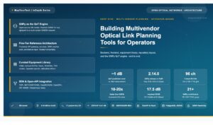
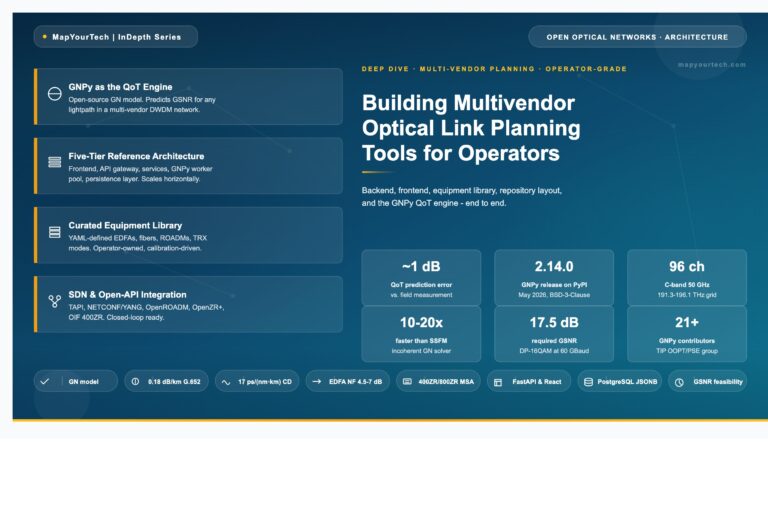
Optical Transceiver Pluggable Nomenclature and Naming Conventions
Personally ,I too get this everytime and thought of putting all together at a place which can help every other Optical Engineers. This comprehensive guide covers the nomenclature, acronyms, and naming conventions for optical fiber communication pluggable transceivers. The optical networking industry has developed various form factors to meet evolving bandwidth demands, from 1 Gigabit to 800 Gigabit and beyond. Understanding these naming conventions is essential for network engineers, system designers, and anyone working with optical communication systems.
Introduction
Optical transceivers are hot-pluggable modules that convert electrical signals to optical signals and vice versa. Over the years, the industry has developed standardized form factors through Multi-Source Agreements (MSAs) to ensure interoperability between equipment from different manufacturers. Each form factor has specific naming conventions that describe its physical characteristics, data rates, and optical interfaces.
Form Factor Nomenclature
GBIC - Gigabit Interface Converter
Full Form: Gigabit Interface Converter
Description: An early form factor transceiver that preceded the SFP. GBIC modules were larger and primarily used for Gigabit Ethernet and Fibre Channel applications.
Data Rates: 1 Gbps
Applications: Legacy gigabit networking
SFP - Small Form-factor Pluggable
Full Form: Small Form-factor Pluggable
Description: A compact, hot-pluggable transceiver that replaced GBIC modules. The term "Small Form-factor" refers to its reduced size compared to GBIC. Also known by identifier code 03h in serial identification standards.
Data Rates: 100 Mbps to 4.25 Gbps
Pin Configuration: 20-pin electrical interface
Applications: Gigabit Ethernet, Fibre Channel, SONET/SDH
Development: Defined by SFF (Small Form Factor) Committee specifications, particularly INF-8074i
SFP+ - Enhanced Small Form-factor Pluggable
Full Form: Enhanced Small Form-factor Pluggable (or SFP Plus)
Description: An evolution of SFP supporting higher data rates. The plus symbol indicates enhanced performance for 10 Gbps applications. Defined in SFF-8431 specification.
Data Rates: 8 Gbps to 16 Gbps (typically 10 Gbps)
Mechanical: Same form factor as SFP
Applications: 10 Gigabit Ethernet, 10G Fibre Channel
Compatibility: Optical interoperability with XFP, X2, and XENPAK modules
SFP-DD - Small Form-factor Pluggable Double Density
Full Form: Small Form-factor Pluggable Double Density
Description: Enhanced SFP with doubled electrical lanes, indicated by "DD" (Double Density). Maintains backward compatibility with SFP/SFP+ in the same port.
Data Rates: Up to 100 Gbps (2 x 50 Gbps lanes)
Applications: 100G Ethernet, cost-effective NIC connectivity
SFP28 - Small Form-factor Pluggable 28 Gbps
Full Form: Small Form-factor Pluggable 28 Gigabit per second
Description: The numerical suffix "28" indicates the electrical signaling rate of 28 Gbps (typically 25 Gbps data rate with encoding overhead).
Data Rates: 25 Gbps
Applications: 25 Gigabit Ethernet
SFP56 - Small Form-factor Pluggable 56 Gbps
Full Form: Small Form-factor Pluggable 56 Gigabit per second
Description: Enhanced SFP supporting 50 Gbps data rates with 56 Gbps signaling using PAM4 modulation.
Data Rates: 50 Gbps
Applications: 50 Gigabit Ethernet
DSFP - Dual Small Form-factor Pluggable
Full Form: Dual Small Form-factor Pluggable
Description: A variant that supports dual rate capabilities in SFP form factor.
Applications: 100G connectivity, particularly for NIC applications
XFP - 10 Gigabit Small Form Factor Pluggable
Full Form: 10 Gigabit Small Form Factor Pluggable
Description: The "X" represents the Roman numeral for 10. Defined in INF-8077i specification. A hot-pluggable, protocol-independent optical transceiver.
Data Rates: 10 Gbps
Identifier Code: 06h
Applications: 10 Gigabit Ethernet, 10G Fibre Channel, SONET OC-192
X2 - 10 Gigabit Transceiver Version 2
Full Form: 10 Gigabit Transceiver (Version 2 or second generation)
Description: An earlier 10 Gbps transceiver form factor. The "X" represents Roman numeral 10, and "2" indicates second generation design.
Data Rates: 10 Gbps
Identifier Code: 0Ah
Applications: 10 Gigabit Ethernet
XENPAK - 10 Gigabit Ethernet Network Protocol Attachment Kit
Full Form: 10 Gigabit Ethernet Network Protocol Attachment Kit
Description: One of the first 10 Gigabit Ethernet transceiver modules. The "X" represents 10 (Roman numeral), "EN" for Ethernet, and "PAK" for package.
Data Rates: 10 Gbps
Identifier Code: 05h
Characteristics: Larger form factor compared to XFP and X2
XPAK - 10 Gigabit Package
Full Form: 10 Gigabit Package
Description: A variant of XENPAK with slightly different dimensions.
Identifier Code: 09h
XFF - 10 Gigabit Form Factor
Full Form: 10 Gigabit Form Factor
Identifier Code: 07h
XFP-E - Enhanced XFP
Full Form: Enhanced 10 Gigabit Small Form Factor Pluggable
Identifier Code: 08h
QSFP - Quad Small Form-factor Pluggable
Full Form: Quad Small Form-factor Pluggable
Description: The "Q" prefix indicates "Quad" meaning four channels. Four parallel electrical and optical lanes enable 4x data transmission.
Data Rates: 4 Gbps (4x1G) initially
Identifier Code: 0Ch
Specification: Defined by SFF-8436
QSFP+ - Quad Small Form-factor Pluggable Plus
Full Form: Quad Small Form-factor Pluggable Plus (or Enhanced)
Description: Enhanced version supporting 4x10 Gbps channels for 40G operations. The module contains 4 independent transmit and receive channels. Referenced in SFF-8436.
Data Rates: 40 Gbps (4 x 10 Gbps lanes)
Identifier Code: 0Dh
Applications: 40 Gigabit Ethernet, InfiniBand QDR
Note: Universal transceiver supporting both multi-mode and single-mode fiber
QSFP14 - Quad Small Form-factor Pluggable 14 Gbps
Full Form: Quad Small Form-factor Pluggable 14 Gigabit per second
Description: The numerical suffix indicates 14 Gbps per lane electrical signaling (4x14G).
Specification: SFF-8685
QSFP28 - Quad Small Form-factor Pluggable 28 Gbps
Full Form: Quad Small Form-factor Pluggable 28 Gigabit per second
Description: "28" indicates the electrical signaling rate of 28 Gbps per lane (typically 25 Gbps data rate with 25.78125 Gbps signaling). Four lanes provide 100 Gbps total.
Data Rates: 100 Gbps (4 x 25 Gbps)
Applications: 100 Gigabit Ethernet, 100G InfiniBand EDR
Specification: SFF-8665
Evolution: Drove widespread cost-effective adoption of 100G after earlier CFP/CFP2 implementations
QSFP56 - Quad Small Form-factor Pluggable 56 Gbps
Full Form: Quad Small Form-factor Pluggable 56 Gigabit per second
Description: "56" indicates PAM4 signaling at 56 Gbps per lane (50 Gbps data rate). Four lanes provide 200 Gbps total.
Data Rates: 200 Gbps (4 x 50 Gbps)
Applications: 200 Gigabit Ethernet
QSFP112 - Quad Small Form-factor Pluggable 112 Gbps
Full Form: Quad Small Form-factor Pluggable 112 Gigabit per second
Description: "112" indicates PAM4 signaling at approximately 112 Gbps per lane (106.25 Gbaud). Four lanes provide 400 Gbps total.
Data Rates: 400 Gbps (4 x 100 Gbps)
Applications: 400 Gigabit Ethernet
Specification: QSFP112 MSA, SFF-8679 electrical specification
QSFP-DD - Quad Small Form-factor Pluggable Double Density
Full Form: Quad Small Form-factor Pluggable Double Density
Description: "DD" indicates Double Density with 8 electrical lanes (double the 4 lanes of standard QSFP). Can support legacy QSFP28 modules in the same port.
Data Rates: 400 Gbps (8 x 50 Gbps PAM4), 800 Gbps (8 x 100 Gbps PAM4)
Electrical Interface: 8 x 53.125 GBd/s PAM4 for 400G, or 8 x 106.25 GBd/s PAM4 for 800G
Applications: 400/800 Gigabit Ethernet, data center interconnect
Management: Uses CMIS 4.0 interface
Power: Maximum 12W for optical modules
Form Factor Types: Type 1 (78.3mm depth) and Type 2 (93.3mm depth)
CFP - 100G Form-factor Pluggable
Full Form: 100G Form-factor Pluggable (C = Centum, Latin for 100)
Description: "C" represents 100 in Roman numerals (Centum). First-generation 100G pluggable module with 10 Gbps per lane signaling.
Data Rates: 40 Gbps and 100 Gbps
Electrical Interface: 10 x 10 Gbps lanes, or 4 x 25 Gbps lanes
Pin Configuration: 148-pin connector (later reduced to 104 pins in CFP2)
Applications: 100 Gigabit Ethernet, OTN OTU4
Interface Standards: CAUI, XLAUI, OTL4.10, OTL3.4, STL256.4
Management: MDIO interface
CFP2 - 100G Form-factor Pluggable Version 2
Full Form: 100G Form-factor Pluggable Version 2
Description: Second generation CFP with reduced size. Approximately half the volume of original CFP while maintaining similar performance.
Data Rates: 10 Gbps, 40 Gbps, 100 Gbps, and 400 Gbps interfaces
Electrical Interface: Nominal 25 Gbps per lane (4 x 25G or 8 x 25G), also supports 10 Gbps per lane
Pin Configuration: 104-pin connector
Interface Standards: OIF CEI-28G-VSR, CAUI-4, OTL4.4, also supports CEI-56G-VSR for 50 Gbps per lane
CFP4 - 100G Form-factor Pluggable Quarter Size
Full Form: 100G Form-factor Pluggable Quarter Size
Description: "4" indicates approximately quarter the size of original CFP. An early competitor to QSFP28 but QSFP28 achieved greater market adoption.
Applications: 100 Gigabit Ethernet
CFP8 - 100G Form-factor Pluggable Eighth Size
Full Form: 100G Form-factor Pluggable Eighth Size
Description: "8" indicates approximately one-eighth the size of original CFP. Used for early 400G development but did not become the dominant form factor.
CPAK - Cisco Pluggable Advanced Kit
Full Form: Cisco Pluggable Advanced Kit
Description: A proprietary form factor for 100G applications, similar in concept to CFP2.
Applications: 100 Gigabit Ethernet
Note: Primarily used in equipment from a single major manufacturer
OSFP - Octal Small Form-factor Pluggable
Full Form: Octal Small Form-factor Pluggable
Description: "O" prefix indicates "Octal" meaning eight channels. Eight parallel electrical and optical lanes enable 8x data transmission. Larger than QSFP-DD but offers superior thermal performance.
Data Rates: 400 Gbps (8 x 50 Gbps), 800 Gbps (8 x 100 Gbps)
Electrical Interface: 8 x 53.125 GBd/s PAM4 for 400G
Dimensions: 13.0 x 22.6 x 100.4mm (larger than QSFP-DD)
Power: Maximum 12W for optical modules
Applications: 400/800 Gigabit Ethernet, high-power coherent optics
Advantages: Better power handling and cooling compared to QSFP-DD
OSFP-RHS - Octal Small Form-factor Pluggable Reduced Height Short
Description: A variant of OSFP with reduced height for specific applications.
OSFP-XD - Octal Small Form-factor Pluggable Extended Depth
Description: Extended depth variant of OSFP for applications requiring additional module volume.
Optical Interface Naming Conventions
Beyond form factors, optical transceivers use systematic naming conventions to describe their optical characteristics, reach, and medium type. These names typically follow the pattern: [Speed]BASE-[Type][Distance/Characteristic]
Speed Designations
| Designation | Speed | Example |
|---|---|---|
| 1000 | 1 Gigabit per second | 1000BASE-T |
| 10G | 10 Gigabits per second | 10GBASE-SR |
| 25G | 25 Gigabits per second | 25GBASE-LR |
| 40G | 40 Gigabits per second | 40GBASE-LR4 |
| 50G | 50 Gigabits per second | 50GBASE-CR |
| 100G | 100 Gigabits per second | 100GBASE-SR4 |
| 200G | 200 Gigabits per second | 200GBASE-FR4 |
| 400G | 400 Gigabits per second | 400GBASE-DR4 |
| 800G | 800 Gigabits per second | 800GBASE-DR8 |
Optical Type Suffixes
| Suffix | Full Name | Description | Typical Reach |
|---|---|---|---|
| SR | Short Range | Multi-mode fiber using 850nm wavelength | 70-100m (OM3/OM4) |
| VSR | Very Short Range | Multi-mode fiber, shorter distances | 30-50m |
| XSR | Extended Short Range | Extended multi-mode fiber reach | 150-300m |
| LR | Long Range | Single-mode fiber using 1310nm wavelength | 10km |
| LRL | Long Range Lite | Reduced reach single-mode | 2km |
| DR | Data Rate (or Data Room) | Single wavelength on single-mode fiber, 1310nm | 500m |
| FR | Fiber Range (or Four wavelengths Reduced reach) | Four wavelengths, 1310nm band single-mode | 2km |
| ER | Extended Range | Long distance single-mode fiber | 40km |
| ERL | Extended Range Lite | Extended reach variant | 30-40km |
| ZR | Zero-chirp Range (or Extended Extended Range) | Very long distance single-mode | 80km+ |
| PSM | Parallel Single-Mode | Parallel single-mode fiber ribbons | 500m |
| PLR | Parallel Long Range | Parallel single-mode fibers | 10km |
| PLRL | Parallel Long Range Lite | Parallel single-mode, reduced reach | 2km |
| CWDM | Coarse Wavelength Division Multiplexing | Multiple wavelengths with 20nm spacing | 2km |
| XCWDM | Extended CWDM | CWDM with extended reach | 10km |
| DWDM | Dense Wavelength Division Multiplexing | Multiple wavelengths with narrow spacing (0.8nm or less) | 80km |
| SWDM | Short Wavelength Division Multiplexing | Multiple wavelengths in 850nm band on multi-mode | 70-100m |
| BiDi | Bi-Directional | Different transmit and receive wavelengths on single fiber | 70-100m |
| LAN-WDM | Local Area Network Wavelength Division Multiplexing | Four wavelengths around 1310nm band | Varies |
Numerical Suffixes
4, 8, 10, 12: Indicates number of optical wavelengths or lanes
- SR4: Short Range with 4 wavelengths/lanes (e.g., 100GBASE-SR4 uses 4 x 25G lanes)
- SR8: Short Range with 8 wavelengths/lanes (e.g., 400GBASE-SR8 uses 8 x 50G lanes)
- LR4: Long Range with 4 wavelengths (e.g., 100GBASE-LR4 uses 4 LAN-WDM wavelengths)
- LR8: Long Range with 8 wavelengths (e.g., 400GBASE-LR8 uses 8 LAN-WDM wavelengths)
Cable Type Designations
| Suffix | Full Name | Description |
|---|---|---|
| CR | Copper (Direct Attach Cable) | Passive twinax copper cable |
| ACC | Active Copper Cable | Active twinax with signal conditioning |
| AOC | Active Optical Cable | Pre-terminated fiber with integrated transceivers |
| T | Twisted Pair | Copper twisted pair (typically Cat6a) |
Coherent Optics Nomenclature
OpenZR+ and 400ZR Standards
400ZR: 400G Zero-chirp Range - Digital coherent optical interface for data center interconnect, defined by Optical Internetworking Forum (OIF)
OpenZR+: Open 400G Zero-chirp Range Plus - MSA specification extending 400ZR with flexible reaches, modulation types, and rates
OpenZR+ Components:
- DSP: Digital Signal Processor
- FEC: Forward Error Correction
- OSNR: Optical Signal-to-Noise Ratio
- DWDM: Dense Wavelength Division Multiplexing (C-band, typically 1528-1566nm)
Reach: Up to 120km with optical amplification (EDFA - Erbium-Doped Fiber Amplifier)
Evolution: 800ZR and 1600ZR standards under development for 800G and 1.6T coherent
Management Interface Acronyms
Serial management interface used in CFP modules
Two-wire serial interface used in SFP modules for identification and monitoring
Standardized management interface for high-speed modules (QSFP-DD, OSFP, QSFP112).
Version History:
- CMIS 4.0: QSFP-DD, basic 400G support
- CMIS 5.0: Enhanced diagnostics, coherent support
- CMIS 5.1: 800G and LPO support, improved telemetry
- CMIS 5.2+: 1.6T support, advanced features
Feature providing real-time monitoring of transceiver parameters
Electrical Interface Standards
| Acronym | Full Name | Description |
|---|---|---|
| CAUI | 100G Attachment Unit Interface | 10 x 10 Gbps electrical interface for 100G modules |
| CAUI-4 | 100G Attachment Unit Interface - 4 lane | 4 x 25 Gbps electrical interface |
| XLAUI | 40G Attachment Unit Interface | 4 x 10 Gbps electrical interface |
| SFI | SerDes Framer Interface | High-speed serial interface for SFP+ |
| CEI | Common Electrical Interface | OIF standard for chip-to-module electrical interfaces |
| CEI-28G-VSR | Common Electrical I/O 28 Gbps Very Short Reach | Electrical specification for 25 Gbps signaling |
| CEI-56G-VSR | Common Electrical I/O 56 Gbps Very Short Reach | Electrical specification for 50 Gbps signaling |
Continue Reading This Article
Sign in with a free account to unlock the full article and access the complete MapYourTech knowledge base.
Modulation and Encoding
NRZ - Non-Return to Zero
Traditional binary modulation format used for speeds up to 28 Gbps per lane. Each symbol represents one bit.
PAM4 - Pulse Amplitude Modulation 4-level
Advanced modulation using four amplitude levels per symbol, effectively doubling data rate. Each symbol represents 2 bits. Used in 50G and 100G per lane applications.
- 53.125 GBd PAM4 = 50 Gbps per lane (after encoding overhead)
- 106.25 GBd PAM4 = 100 Gbps per lane (after encoding overhead)
Encoding Standards
- 8B/10B: 8 bits encoded into 10 bits for DC balance
- 64B/66B: 64 bits encoded into 66 bits for higher efficiency
- 4B5B: 4 bits encoded into 5 bits
Connector Types
| Acronym | Full Name | Description |
|---|---|---|
| LC | Lucent Connector (or Little Connector) | Small form factor duplex connector, most common for single-mode |
| SC | Subscriber Connector (or Standard Connector) | Push-pull connector, square form factor |
| MPO | Multi-fiber Push On | Multi-fiber connector for parallel optics |
| MPO-12 | Multi-fiber Push On 12-fiber | 12-fiber MPO connector for parallel applications |
| MPO-16 | Multi-fiber Push On 16-fiber | 16-fiber MPO connector for higher density parallel applications |
| MTP | Mechanical Transfer Push-on | High-performance variant of MPO with better alignment |
| CS | Connection System | Dual duplex LC connector system |
| SN | Senko Narrow | Narrow form factor connector for high-density applications |
- UPC (Ultra Physical Contact): Standard polish for multi-mode applications
- APC (Angled Physical Contact): 8-degree angle polish for single-mode, reduces back reflections
Fiber Types
| Designation | Full Name | Core Size | Typical Use |
|---|---|---|---|
| SMF | Single-Mode Fiber | 8-10 µm | Long distance, 1310nm or 1550nm |
| MMF | Multi-Mode Fiber | 50 µm or 62.5 µm | Short distance, typically 850nm |
| OM3 | Optical Multi-mode 3 | 50 µm | 2000 MHz·km modal bandwidth at 850nm |
| OM4 | Optical Multi-mode 4 | 50 µm | 4700 MHz·km modal bandwidth at 850nm |
| OM5 | Optical Multi-mode 5 | 50 µm | Optimized for SWDM applications, multi-wavelength |
| G.652 | ITU-T Standard Single-Mode | ~9 µm | Standard single-mode fiber for telecom |
Standards Organizations
Industry groups that define specifications for interoperable products from multiple vendors
Develops Ethernet standards (802.3 series)
Committee that developed SFP, QSFP specifications
Develops optical networking specifications including CEI, 400ZR
Develops telecom standards including OTN (G.709), fiber specs
Standardization body that adopted many SFF specifications
Oversees development of voluntary consensus standards
International standards organization for electrical technologies
InfiniBand and Data Center Protocols
While Ethernet dominates most optical networking, InfiniBand remains important for high-performance computing and AI/ML clusters:
InfiniBand Data Rates
| InfiniBand Rate | Speed per Lane | Total (4x) | Form Factor |
|---|---|---|---|
| SDR | 2.5 Gbps | 10 Gbps | QSFP |
| DDR | 5 Gbps | 20 Gbps | QSFP |
| QDR | 10 Gbps | 40 Gbps | QSFP+ |
| FDR | 14.0625 Gbps | 56 Gbps | QSFP+ |
| EDR | 25 Gbps | 100 Gbps | QSFP28 |
| HDR | 50 Gbps | 200 Gbps | QSFP56 |
| NDR | 100 Gbps | 400 Gbps | QSFP112 |
| XDR | 250 Gbps | 1000 Gbps | Future |
InfiniBand Naming:
- SDR: Single Data Rate
- DDR: Double Data Rate
- QDR: Quad Data Rate
- FDR: Fourteen Data Rate (14 Gbps signaling)
- EDR: Enhanced Data Rate
- HDR: High Data Rate
- NDR: Next Data Rate
- XDR: eXtreme Data Rate
Applications: High-performance computing, AI/ML training clusters, financial trading systems, scientific computing
Fibre Channel
Storage area network protocol with its own speed designations:
| Fibre Channel | Speed | Common Form Factor |
|---|---|---|
| 1GFC | 1.0625 Gbps | SFP |
| 2GFC | 2.125 Gbps | SFP |
| 4GFC | 4.25 Gbps | SFP |
| 8GFC | 8.5 Gbps | SFP+ |
| 10GFC | 10.52 Gbps | SFP+ |
| 16GFC | 14.025 Gbps | SFP+ |
| 32GFC | 28.05 Gbps | SFP28 |
| 64GFC | 56.1 Gbps | SFP56 |
| 128GFC | ~112 Gbps | SFP-DD/QSFP28 |
Applications: Enterprise storage networks, SAN infrastructure
Additional Technical Acronyms
Circuit that extracts timing and data from serial signals
Converts parallel data to serial and vice versa
Optical transmitter component in a transceiver
Optical receiver component in a transceiver
Laser type commonly used in multi-mode applications at 850nm
Laser type used for single-mode applications
Advanced laser technology for high-speed modulation
Basic laser type for lower-cost applications
Photodiode type used in optical receivers
High-sensitivity photodiode for long-reach applications
Amplifier that converts photodiode current to voltage
Error correction coding to improve link performance
Power Classifications
QSFP+ Power Classes
| Class | Maximum Power |
|---|---|
| Power Class 1 | 1.5W |
| Power Class 2 | 2.0W |
| Power Class 3 | 2.5W |
| Power Class 4 | 3.5W |
Note: Power consumption varies by application. High-speed modules (QSFP-DD, OSFP) typically consume up to 12W for optical modules, with coherent ZR modules consuming more.
Naming Convention Examples
Example 1: QSFP-100G-SR4
- QSFP: Quad Small Form-factor Pluggable (4 lanes)
- 100G: 100 Gigabit per second total data rate
- SR: Short Range (multi-mode fiber, 850nm)
- 4: Four parallel optical lanes (4 x 25G)
Summary: 100 Gigabit QSFP module with 4 parallel 25G lanes for short-range multi-mode fiber applications up to 100m on OM4.
Example 2: QSFP-DD-400G-DR4
- QSFP-DD: Quad Small Form-factor Pluggable Double Density (8 lanes)
- 400G: 400 Gigabit per second
- DR: Data Rate/Data Room
- 4: Four parallel optical wavelengths (4 x 100G)
Summary: 400 Gigabit QSFP-DD module with 4 parallel 100G wavelengths at 1310nm for single-mode fiber up to 500m.
Example 3: OSFP-400G-LR8
- OSFP: Octal Small Form-factor Pluggable (8 lanes)
- 400G: 400 Gigabit per second
- LR: Long Range
- 8: Eight parallel wavelengths (8 x 50G)
Summary: 400 Gigabit OSFP module with 8 LAN-WDM wavelengths for single-mode fiber up to 10km.
Example 4: SFP-10G-LRM
- SFP: Small Form-factor Pluggable
- 10G: 10 Gigabit per second
- LRM: Long Reach Multi-mode (1310nm on multi-mode fiber)
Summary: 10 Gigabit SFP+ module optimized for extended reach on multi-mode fiber.
Next-Generation and Future Form Factors
QSFP-DD1600 - 1.6 Terabit QSFP Double Density
Full Form: Quad Small Form-factor Pluggable Double Density 1600 Gigabit per second
Description: The latest evolution in the QSFP-DD family, supporting 1.6 Tbps aggregate bandwidth. "1600" indicates the total data rate in Gbps. Eight electrical lanes each operating at 200 Gbps (using advanced PAM4 signaling at approximately 200 Gbaud).
Data Rates: 1.6 Tbps (8 x 200 Gbps PAM4)
Electrical Interface: 8 x 200 Gbps PAM4 lanes
Backward Compatibility: Fully backward compatible with QSFP-DD800, QSFP-DD, QSFP112, QSFP56, QSFP28, and legacy QSFP modules
Specification: QSFP-DD Hardware Specification Rev 7.1 (June 2024)
Applications: Next-generation data centers, AI/ML infrastructure, 1.6T Ethernet
Standards Support: Designed for IEEE 802.3dj (1.6T Ethernet, in development)
Key Features:
- Maintains current QSFP-DD port density
- Enhanced thermal management with riding heatsink
- Optimized for next-generation ASIC capacities (51.2T and beyond)
- Investment protection through backward compatibility
OSFP800 - Octal Small Form-factor Pluggable 800G
Description: 800G variant of OSFP form factor with enhanced power handling for high-performance applications.
Data Rates: 800 Gbps (8 x 100 Gbps PAM4)
Applications: High-power 800G coherent optics, advanced modulation schemes
OSFP1600 - Octal Small Form-factor Pluggable 1.6T
Description: 1.6 Terabit variant of OSFP, designed for the highest power and thermal requirements.
Data Rates: 1.6 Tbps (8 x 200 Gbps PAM4)
Applications: Ultra-high-speed data center interconnect, AI cluster networking
OSFP-XD - Octal Small Form-factor Pluggable Extended Depth
Full Form: Octal Small Form-factor Pluggable Extended Depth
Description: "XD" indicates Extended Depth variant providing additional module volume for complex optical engines and higher power applications.
Variants: OSFP-XD800, OSFP-XD1600
Applications: Long-reach coherent optics requiring larger DSP and optical components
OSFP-XD-RHS - OSFP Extended Depth Reduced Height Short
Description: Combines extended depth with reduced height for specific system designs.
Emerging Technologies and Paradigm Shifts
LPO - Linear Pluggable Optics
Full Form: Linear Pluggable Optics
Description: Revolutionary approach that eliminates retiming DSP (Digital Signal Processor) from the optical module, relying instead on the capabilities of ASIC SerDes for signal equalization. "Linear" refers to the linear (non-retimed) signal path.
Key Characteristics:
- Power Reduction: Significant power savings (~50-60%) compared to retimed optics by removing DSP circuits
- Cost Optimization: Lower component count reduces manufacturing costs
- Performance Dependency: Relies on quality of entire link (ASIC SerDes, PCB traces, connectors, optics)
- Limited Reach: Typically optimized for intra-rack or short inter-rack connections (0.5m to 3m)
- Silicon Photonics: Benefits from linear characteristics of SiPhotonics components
Trade-offs:
- Reduced telemetry and diagnostic capabilities
- More challenging interoperability (requires careful system design)
- Port-to-port performance variation based on channel quality
- Limited or no FEC monitoring capabilities
Power Comparison @ 800G:
- Retimed optics: ~15-16W
- LPO optics: ~6-9W
- System power savings: ~700W demonstrated in 64-port switches
Form Factors: Available in OSFP and QSFP-DD variants (LPO-800G-DR8, LPO-800G-2DR4)
Applications: AI/ML clusters, high-density switching fabrics, GPU interconnects
MSA Status: LPO MSA formed with industry-wide participation
CPO - Co-Packaged Optics
Full Form: Co-Packaged Optics
Description: Revolutionary architecture integrating optical engines directly onto the switch ASIC package, eliminating traditional pluggable modules for highest-density ports. "Co-Packaged" indicates optics and ASIC are integrated in a single package.
Key Characteristics:
- Integration Level: Optical components mounted directly on ASIC substrate or interposer
- Power Efficiency: Eliminates pluggable module overhead and SerDes power
- Density: Enables port counts not possible with pluggables
- System Demonstration: 22% total system power reduction achieved in 25.6T switch demonstrations
Architecture Options:
- Integrated Laser: Light source on package
- External Light Source (ELSFP): Separate external laser modules feeding optical engines
Challenges:
- Reduced serviceability (optics not field-replaceable)
- Complex thermal management
- Manufacturing complexity and yield
- Limited flexibility in port configuration
Target Applications: Spine switches, AI training clusters, hyperscale data centers
Industry Status: Demonstration phase, not yet in volume production
Silicon Photonics Integration
Description: Technology enabling optical components to be manufactured using standard semiconductor fabrication processes, enabling lower costs and higher integration.
Benefits for Future Transceivers:
- Enables LPO implementations with improved linearity
- Facilitates CPO integration
- Reduces manufacturing costs through CMOS-compatible processes
- Enables higher levels of integration (multiple functions per chip)
Advanced Cooling Technologies
As transceiver power increases with data rates, advanced cooling becomes essential:
Riding Heat Sinks
Heat sinks that "ride" on top of modules, crucial feature of QSFP-DD design that enables:
- Superior thermal performance in high-density configurations
- Backward compatibility (different height modules use same heat sink)
- Optimized airflow in stacked configurations
Liquid Cooling
Direct liquid cooling for switches and networking equipment, becoming necessary for:
- AI/ML infrastructure with 800G and 1.6T ports
- High-power coherent optics (>15W per port)
- Dense switch fabrics (64+ ports of 800G in 2RU)
Immersion Cooling
Complete immersion of equipment in dielectric fluid for maximum thermal performance in extreme-density deployments.
Future IEEE Standards and Industry Initiatives
IEEE 802.3df - 800 Gigabit Ethernet
Status: Published March 2024
Description: Formal standard defining 800 Gbps Ethernet using 100 Gbps per lane signaling (8 lanes)
Key PMDs:
- 800GBASE-DR8: 8 parallel lanes at 1310nm, 500m reach
- 800GBASE-SR8: 8 parallel lanes at 850nm on MMF
- 800GBASE-VR8/CR8: Copper variants
Significance: Enables broad interoperability for 800G ecosystem
IEEE 802.3dj - 1.6 Terabit Ethernet (In Development)
Status: In development (originally targeted 2026, may slip)
Scope:
- Define Ethernet MAC parameters for 1.6 Tb/s
- Physical layer specifications using 200 Gb/s per lane signaling
- Also defines 200G/400G/800G using 200G lanes where applicable
- Covers both copper (CR) and single-mode fiber PMDs
Technology Base: 200 Gbps PAM4 per lane (8 lanes = 1.6T)
Form Factors: QSFP-DD1600, OSFP1600
IEEE 802.3ck - 100G Signaling Electrical Interfaces
Description: Defines electrical interface specifications for 100 Gb/s, 200 Gb/s, and 400 Gb/s based on 100 Gb/s signaling
Applications: Chip-to-module interfaces for 800G modules
IEEE 802.3db - 100G Signaling Optical
Description: Physical layer specifications for 100 Gb/s, 200 Gb/s, and 400 Gb/s operation over optical fiber using 100 Gb/s signaling
Applications: 800G optical PMD definitions
OIF 800ZR and 1600ZR (In Development)
800ZR: 800 Gigabit Zero-chirp Range coherent standard for DCI applications
800G-LR: Single-wavelength coherent for campus applications up to 10km
1600ZR: Recently initiated in OIF for 1.6 Terabit coherent applications
Channel Spacing Evolution:
- Class 2 (400G): 75 GHz spacing
- Class 3 (800G): 150 GHz spacing
- Class 4 (1.6T): 300 GHz spacing
Modulation Schemes:
- 800G: QPSK (800G), 16QAM (1.2T), 64QAM (1.8T)
- 1.6T: QPSK (1.6T), 16QAM (3.2T), 64QAM (4.8T)
Ethernet Technology Consortium (ETC) 800G
Description: Industry consortium specification that preceded IEEE 802.3df, based on dual instance of 400 GbE PCS/FEC
Role: Enabled early 800G product development while IEEE standard was in progress
Status: Served as industry template, now superseded by IEEE 802.3df
ASIC and SerDes Evolution
Transceiver evolution is driven by ASIC capabilities and roadmaps:
| Year | ASIC Capacity | SerDes Speed | Ports per System | Form Factor |
|---|---|---|---|---|
| 2010 | 640 Gbps | 10G NRZ | 16 x 40G | QSFP+ |
| 2014 | 3.2 Tbps | 25G NRZ | 32 x 100G | QSFP28 |
| 2018 | 12.8 Tbps | 50G PAM4 | 32 x 400G | QSFP-DD |
| 2022 | 25.6 Tbps | 100G PAM4 | 32 x 800G or 64 x 400G | QSFP-DD800/OSFP |
| 2024-2026 | 51.2 Tbps | 200G PAM4 | 32 x 1.6T or 64 x 800G | QSFP-DD1600/OSFP1600 |
| Beyond | 102.4+ Tbps | 400G+ PAM4/PAM6 | TBD | Future form factors |
Key Trend: 320x increase in switching bandwidth over 16 years (2010-2026)
Power Efficiency and Energy Considerations
Why Higher Speeds Matter for Efficiency
Moving to higher port speeds dramatically improves energy efficiency:
Example: 25.6T Network Capacity
| Configuration | System Power | Annual Energy | Space Required |
|---|---|---|---|
| 64 x 400G (12.8T ASICs, multiple switches) | ~3000W | 26,280 kWh/year | Multiple RU + spine |
| 32 x 800G (25.6T ASIC, single switch) | ~400W | 3,504 kWh/year | 2 RU |
| Energy Savings | 87% | 22,776 kWh/year | 83% less space |
AI/ML Impact on Transceiver Development
Artificial Intelligence and Machine Learning workloads are driving unprecedented demands on optical interconnects:
Key Requirements
- Ultra-High Bandwidth: GPU-to-GPU communication requires massive bandwidth (800G, 1.6T per link)
- Low Latency: Training clusters need minimal signal propagation delay
- Power Efficiency: AI infrastructure already consumes significant power; interconnect must minimize overhead
- Scalability: Clusters scale to thousands of GPUs requiring non-blocking fabrics
Technology Responses
- LPO for Power: Reduces interconnect power by 50%+ for intra-cluster connections
- CPO for Density: Enables port counts matching ASIC I/O capabilities
- Advanced Cooling: Liquid cooling becoming standard for AI switches
- 800G/1.6T Deployment: Accelerated timeline compared to traditional data center adoption
Market Impact: AI networking is dominating future design models for data centers, with AI requirements driving faster adoption cycles for new transceiver technologies.
Evolution Timeline
The optical transceiver industry has evolved through several generations:
| Era | Form Factors | Key Developments |
|---|---|---|
| 1990s | GBIC | First hot-pluggable transceivers |
| Early 2000s | SFP, XENPAK, X2, XFP | Miniaturization, 10G introduction |
| Late 2000s | SFP+, QSFP, QSFP+ | Multi-lane parallel optics, 40G deployment |
| Early 2010s | CFP, CFP2, QSFP28 | 100G standardization, form factor consolidation |
| Late 2010s | QSFP56, QSFP-DD, OSFP | 200G and 400G emergence, PAM4 modulation |
| Early 2020s | QSFP112, 400ZR, 800G OSFP/QSFP-DD | 800G deployment, coherent pluggables, higher integration |
| Mid 2020s | QSFP-DD1600, OSFP1600, LPO | 1.6T Ethernet, linear optics, power optimization |
| Future (2025+) | CPO, Advanced Silicon Photonics | Co-packaged optics, 3.2T+, novel architectures |
Future Trends and Predictions
Short Term (2024-2026)
- Volume deployment of 800G in hyperscale data centers
- LPO adoption for AI clusters and short-reach applications
- QSFP-DD1600 sampling and early deployment
- IEEE 802.3dj standard completion
- 800ZR coherent optics maturation
Medium Term (2026-2028)
- 1.6T Ethernet mainstream adoption in hyperscale
- CPO demonstrations and limited deployment
- 1600ZR coherent standards and products
- 200 Gbps per lane electrical interfaces becoming standard
- Advanced modulation (PAM6, PAM8) exploration
Long Term (2028+)
- 3.2T and beyond exploration (400G per lane?)
- Widespread CPO adoption in spine switches
- Novel architectures (photonic switching, optical computing integration)
- Quantum networking interfaces (potentially new form factors)
- Continued consolidation around QSFP-DD and OSFP families with multi-terabit capabilities
Industry Adoption Patterns
Coherent Optics Shift to Pluggables
The coherent optics market has undergone a dramatic shift:
- Historical: Embedded coherent modules dominated (line cards with integrated optics)
- CFP2 Era: First pluggable coherent, but remained minority
- 400G Revolution: 400ZR pluggables "flipped the script" - now 70% of coherent deployments
- Drivers: Router form factor support (QSFP-DD), interoperability, reduced performance gap
- Future: Embedded designs will benefit from alignment with pluggable standards
Form Factor Market Leadership
QSFP-DD Dominance: Leading market adoption for 400G and positioned to continue for 800G and 1.6T due to:
- Backward compatibility with entire QSFP family
- Riding heatsink thermal advantages
- Small faceplate enabling highest density
- Strong ecosystem support
OSFP Growth: Gaining adoption in applications requiring:
- Highest power handling (>15W coherent modules)
- Maximum thermal headroom
- Specific system architectures optimized for OSFP dimensions
Key Takeaways
- Form factor names indicate physical size and lane count (S=Small, Q=Quad, O=Octal, DD=Double Density)
- Numerical suffixes in form factors (28, 56, 112, 800, 1600) indicate electrical signaling rate or aggregate bandwidth
- Optical interface suffixes (SR, LR, DR, FR, ER, ZR) indicate reach and medium type
- Numerical suffixes in optical names indicate lane count (SR4 = 4 lanes, SR8 = 8 lanes)
- PAM4 modulation effectively doubles data rate per lane compared to NRZ at same symbol rate
- Backward compatibility is crucial - newer form factors (QSFP-DD, OSFP) support legacy modules
- ASIC SerDes capabilities drive transceiver evolution - optics follow ASIC roadmaps
- AI/ML workloads are accelerating adoption of 800G and 1.6T technologies
- Power efficiency becoming critical - LPO and CPO addressing power challenges
- Industry moving toward 200 Gbps per lane signaling for 1.6T Ethernet
Quick Reference Glossary
Common Abbreviations Not Covered Above
| Acronym | Full Form | Context |
|---|---|---|
| DAC | Direct Attach Cable | Passive copper twinax cables |
| ACC | Active Copper Cable | Twinax with active equalization |
| AOC | Active Optical Cable | Pre-terminated fiber with integrated optics |
| DCO | Digital Coherent Optics | Coherent transceiver with integrated DSP |
| ACO | Analog Coherent Optics | Coherent with external DSP |
| DSP | Digital Signal Processor | Chip performing signal processing |
| ASIC | Application-Specific Integrated Circuit | Custom silicon for switching/routing |
| DCI | Data Center Interconnect | Connections between data centers |
| RON | Routed Optical Networking | Architecture combining routing and optical |
| ROADM | Reconfigurable Optical Add-Drop Multiplexer | Dynamic wavelength management |
| OLS | Optical Line System | DWDM transport infrastructure |
| EDFA | Erbium-Doped Fiber Amplifier | Optical amplifier for C-band |
| OSNR | Optical Signal-to-Noise Ratio | Quality metric for optical signals |
| BER | Bit Error Rate/Ratio | Error rate measurement |
| pre-FEC BER | Pre-Forward Error Correction BER | Error rate before FEC processing |
| post-FEC BER | Post-Forward Error Correction BER | Error rate after FEC correction |
| KP-FEC | Reed-Solomon Forward Error Correction | FEC scheme for 100G+ optics |
| RS-FEC | Reed-Solomon FEC | IEEE 802.3 FEC standard |
| QPSK | Quadrature Phase Shift Keying | Coherent modulation format (2 bits/symbol) |
| 16QAM | 16 Quadrature Amplitude Modulation | Advanced coherent modulation (4 bits/symbol) |
| 64QAM | 64 Quadrature Amplitude Modulation | High-order modulation (6 bits/symbol) |
| GBaud | Gigabaud | Billion symbols per second |
| UI | Unit Interval | One symbol period |
| PMD | Physical Medium Dependent | Layer defining physical characteristics |
| PCS | Physical Coding Sublayer | Encoding/decoding layer |
| MAC | Media Access Control | Data link layer protocol |
| MII | Media Independent Interface | Standard interface between MAC and PHY |
| GMII | Gigabit MII | 1G version of MII |
| XGMII | 10 Gigabit MII | 10G interface |
| C-band | Conventional band | 1530-1565nm wavelength range for DWDM |
| L-band | Long wavelength band | 1565-1625nm wavelength range |
| O-band | Original band | 1260-1360nm wavelength range |
Document Version: 2.0 - Comprehensive Edition Including Future Technologies
Last Updated: November 2025
For the latest specifications, always refer to the respective standards organizations
References
- IEEE 802.3 Ethernet Standards - https://www.ieee802.org/3/
- SFF Committee Specifications - http://www.sffcommittee.com
- Optical Internetworking Forum (OIF) - https://www.oiforum.com
- QSFP-DD MSA Consortium - http://www.qsfp-dd.com
- OSFP MSA Group - http://www.osfpmsa.org
- QSFP112 MSA - http://www.qsfp112.org
- CFP MSA - http://www.cfp-msa.org
- 100G Lambda MSA - http://100glambda.com
- OpenZR+ MSA - https://openzrplus.org
- Ethernet Technology Consortium - https://ethernettechnology.org
- ITU-T Recommendations - https://www.itu.int/en/ITU-T/
- SNIA (Storage Networking Industry Association) - https://www.snia.org
- InfiniBand Trade Association - https://www.infinibandta.org
- Fibre Channel Industry Association - https://fibrechannel.org
Key Industry Documents
- • IEEE 802.3df-2024: 800 Gigabit Ethernet Standard
- • IEEE 802.3dj (In Development): 1.6 Terabit Ethernet
- • IEEE 802.3ck: 100G Signaling Electrical Interfaces
- • IEEE 802.3db: 100G Signaling Optical PMDs
- • OIF 400ZR Implementation Agreement
- • OIF CEI-112G-VSR: 112 Gbps Electrical Interface
- • CMIS (Common Management Interface Specification) Rev 5.1+
- • SFF-8024: Cross Reference to Industry Product Names
- • SFF-8636: Management Interface for 4-lane Modules
- • Telcordia GR-63-CORE: NEBS Requirements
Document compiled from industry MSA specifications and standards
For the latest specifications, always refer to the respective standards organizations

Optical Communications & Network Automation Expert | Author of 3 Books for Optical Engineers | Founder, MapYourTech
Optical networking engineer with nearly two decades of experience across DWDM, OTN, coherent optics, submarine systems, and cloud infrastructure. Founder of MapYourTech. Read full bio →
Follow on LinkedInRelated Articles on MapYourTech