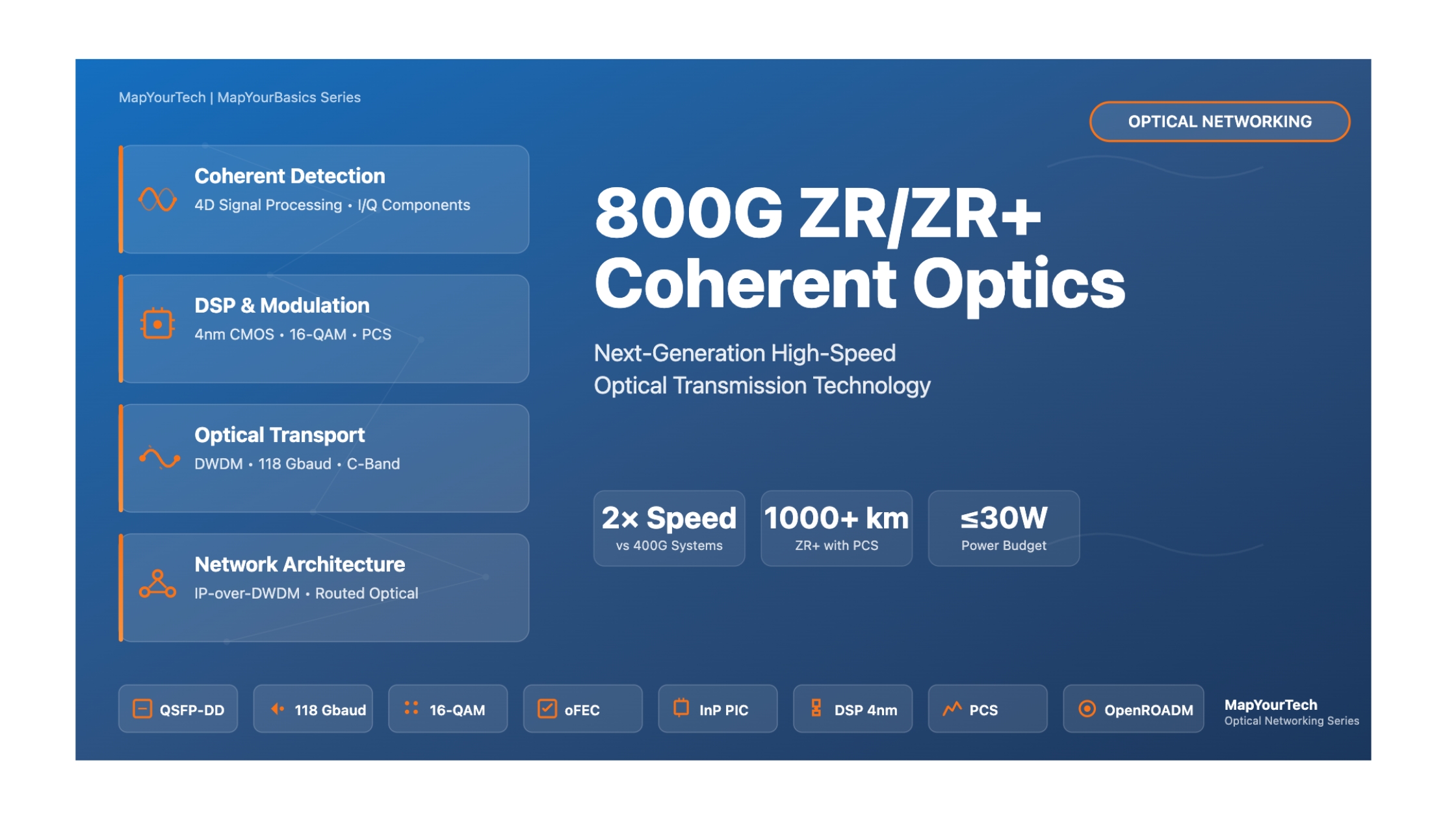

800G ZR/ZR+ Coherent Optics
Comprehensive Technical Guide to Next-Generation High-Speed Optical Networking
Introduction
The exponential growth of cloud computing, artificial intelligence, machine learning, and data-intensive applications has created an unprecedented demand for high-capacity optical networks. As hyperscale data centers expand globally and enterprises digitize operations, the telecommunications industry faces a critical challenge: how to efficiently transport massive amounts of data across metropolitan, regional, and long-haul networks while controlling costs, power consumption, and physical footprint.
Enter 800G ZR and ZR+ coherent optics—a revolutionary technology that represents the next evolutionary leap in optical networking. Building upon the success of 400G ZR/ZR+ implementations, the 800G generation doubles the data rate while maintaining or improving power efficiency, reach capabilities, and operational flexibility. This technology enables network operators to seamlessly scale bandwidth capacity to meet the demands of modern applications including AI workload distribution, real-time analytics, video streaming, and cloud services.
What is 800G ZR/ZR+?
800G ZR and ZR+ are industry-standard specifications for pluggable coherent optical transceivers that enable 800 Gigabit per second data transmission over single-mode fiber. These compact modules, available in QSFP-DD (Quad Small Form-factor Pluggable Double Density) and OSFP (Octal Small Form-factor Pluggable) form factors, plug directly into router ports, eliminating the need for separate optical transport equipment.
800G ZR is defined by the Optical Internetworking Forum (OIF) and targets data center interconnect (DCI) applications with reaches up to 120 kilometers over amplified point-to-point links. It uses 16-QAM (Quadrature Amplitude Modulation) modulation with oFEC (open Forward Error Correction) operating at baud rates around 118 Gbaud.
800G ZR+, standardized by the Open ROADM Multi-Source Agreement, extends the capabilities beyond basic DCI to support metro, regional, and even long-haul applications. ZR+ incorporates advanced features including probabilistic constellation shaping (PCS), flexible modulation formats (QPSK, 8QAM, 16QAM), and higher baud rates (up to 131 Gbaud), enabling transmission distances exceeding 1,000 kilometers in optimal configurations.
Why 800G ZR/ZR+ Matters
The significance of 800G coherent optics extends far beyond simply doubling the speed of 400G technology. This advancement represents a fundamental shift in network architecture philosophy—the convergence of IP and optical layers into a unified Routed Optical Networking (RON) infrastructure. Here's why this technology is transformative:
Architectural Simplification: By integrating coherent optics directly into routers, 800G ZR/ZR+ eliminates entire layers of optical transport equipment including external transponders, dedicated optical line systems, and associated power and cooling infrastructure. This consolidation reduces capital expenditures by 40-65% and operational expenses by 50-76% according to industry deployments.
Power Efficiency Revolution: Modern 4-nanometer CMOS DSP (Digital Signal Processor) technology enables 800G modules to achieve maximum power consumption of just 30 watts—remarkably efficient considering they handle twice the data rate of 400G predecessors. When network-wide power savings are calculated, operators report up to 97% energy reduction compared to traditional architectures, a critical advantage as sustainability becomes paramount.
Flexibility and Scalability: 800G ZR+ modules support multiple operational modes, allowing a single transceiver to adapt to different network scenarios. The same module can operate at 800G for short metro links, throttle down to 600G or 400G for extended reach, or even run legacy 400G modes for backward compatibility. This flexibility maximizes investment protection and simplifies inventory management.
Multi-Vendor Interoperability: Unlike proprietary optical systems of the past, 800G ZR/ZR+ is built on open standards ensuring interoperability between equipment from different manufacturers. Network operators can select best-of-breed components, avoid vendor lock-in, and create more resilient, diverse supply chains—a crucial capability in today's geopolitical landscape.
Real-World Applications and Industry Adoption
The deployment of 800G coherent optics is accelerating rapidly across diverse network segments. Hyperscale cloud providers including major technology companies are implementing 800G ZR+ to interconnect geographically distributed AI training clusters, where massive datasets must traverse hundreds or thousands of kilometers between data centers. The technology's combination of high capacity and extended reach makes it ideal for these demanding applications.
Service providers are leveraging 800G ZR/ZR+ to modernize metropolitan and regional networks, replacing aging DWDM (Dense Wavelength Division Multiplexing) systems with IP-over-DWDM architectures that offer superior agility, automation, and operational efficiency. Early adopters report dramatic improvements in service velocity—the ability to provision new bandwidth services in minutes rather than weeks.
Financial institutions, healthcare organizations, and enterprises with multi-site operations are exploring 800G technology for private network interconnections, recognizing that direct router-to-router optical connectivity provides lower latency, enhanced security, and better total cost of ownership compared to purchasing dedicated wavelength services from carriers.
Key Concepts
Before diving into detailed technical content, let's preview several fundamental concepts that form the foundation of 800G coherent optics:
Coherent Detection: Unlike traditional intensity modulation and direct detection (IMDD) where information is encoded only in light intensity, coherent systems encode data in both the amplitude and phase of the optical carrier. A local oscillator laser at the receiver mixes with the incoming signal, enabling extraction of both in-phase (I) and quadrature (Q) components across two polarizations—effectively utilizing four dimensions for data transmission.
Digital Signal Processing: Modern coherent transceivers incorporate sophisticated DSPs that perform real-time compensation for chromatic dispersion, polarization mode dispersion, nonlinear fiber effects, and other impairments. These chips, manufactured on advanced 4-nanometer CMOS processes, execute trillions of operations per second while maintaining power consumption below 30 watts.
Pluggable Form Factors: The QSFP-DD and OSFP form factors represent remarkable engineering achievements, packing coherent optical engines that previously required blade-sized line cards into modules smaller than a USB thumb drive. The QSFP-DD measures just 72mm × 18mm × 8.5mm yet delivers up to 800 Gbps bandwidth with reaches exceeding 500 kilometers.
IP-over-DWDM Architecture: This paradigm shift eliminates the traditional three-layer model (IP routers → optical transponders → optical line system) by collapsing functionality into two layers (routers with integrated coherent optics → simplified ROADM infrastructure). The result is a flatter, more efficient network architecture better aligned with modern traffic patterns.
With these foundational concepts in mind, let's begin our comprehensive exploration of 800G ZR/ZR+ technology, starting with the historical context that led to this revolutionary advancement in optical networking.
Historical Context & Evolution
The journey to 800G coherent optics represents decades of innovation, scientific breakthroughs, and engineering refinement. Understanding this evolution provides critical context for appreciating the sophistication of modern transceivers and anticipating future developments.
The Early Days: Intensity Modulation and Direct Detection (1980s-2000s)
The first generation of fiber optic communications relied entirely on intensity modulation and direct detection (IMDD). Transmitters simply turned lasers on and off to represent binary data, while receivers used photodiodes to detect light intensity variations. This straightforward approach worked remarkably well for short distances and moderate data rates, forming the backbone of early telecommunications networks.
As demand for bandwidth grew throughout the 1990s, engineers pushed IMDD technology to its limits. Dense Wavelength Division Multiplexing (DWDM) emerged, allowing multiple wavelength channels to coexist on a single fiber. By the early 2000s, commercial systems achieved 10 Gbps per wavelength with hundreds of wavelengths per fiber, delivering multi-terabit aggregate capacity over long-haul submarine and terrestrial routes.
However, IMDD faced fundamental physical limitations. Chromatic dispersion—the wavelength-dependent propagation velocity in optical fiber—caused pulse broadening that limited reach and data rates. Polarization mode dispersion (PMD) introduced additional signal distortion. Most critically, IMDD only utilized light intensity for information encoding, leaving amplitude, phase, and polarization unutilized—wasting much of the optical spectrum's potential information-carrying capacity.
The Coherent Revolution (2005-2015)
The mid-2000s witnessed a paradigm shift with the commercial introduction of coherent detection technology. While coherent concepts had been researched since the 1980s, practical implementation required advances in several enabling technologies: high-speed analog-to-digital converters, powerful digital signal processors, and precise polarization control.
Coherent systems represented a fundamental departure from IMDD. Instead of detecting only light intensity, coherent receivers mixed the incoming signal with a local oscillator laser, converting optical frequencies down to electrical baseband where both amplitude and phase information could be extracted. This allowed encoding data in four dimensions: in-phase and quadrature components of two orthogonal polarizations—quadrupling information capacity compared to IMDD.
Continue Reading This Article
Sign in with a free account to unlock the full article and access the complete MapYourTech knowledge base.
Core Concepts & Fundamentals
To truly understand 800G ZR/ZR+ technology, we must explore the fundamental principles that enable these remarkable devices to transport data at unprecedented speeds over hundreds of kilometers of optical fiber. This section builds your knowledge from basic concepts through advanced techniques, providing the foundation needed to appreciate the sophisticated engineering embodied in modern coherent transceivers.
Coherent Detection: The Foundation
Coherent detection represents the cornerstone innovation that differentiates modern optical systems from their predecessors. To understand its power, we first contrast it with traditional intensity modulation and direct detection (IMDD).
IMDD Systems: The Traditional Approach
In IMDD systems, information is encoded solely in the intensity (brightness) of light. The transmitter modulates a laser's optical power—typically using on-off keying where "1" corresponds to high intensity and "0" to low intensity. The receiver uses a simple photodiode that converts optical power directly to electrical current, which is then processed to recover the data.
While straightforward and cost-effective, IMDD suffers severe limitations. First, it utilizes only one dimension (intensity) of the electromagnetic field for information encoding. Second, chromatic dispersion causes different wavelengths to travel at different speeds, broadening transmitted pulses and eventually causing inter-symbol interference. Third, polarization mode dispersion further distorts signals. Fourth, photodetection is a "square-law" process that destroys phase information, preventing electronic compensation of many impairments.
Coherent Systems: Unlocking All Four Dimensions
Coherent detection fundamentally changes the reception process. Instead of directly detecting optical power, the incoming signal is combined with a Local Oscillator (LO) laser at the receiver in an optical device called a 90-degree hybrid. This mixing operation—analogous to superheterodyne radio receivers—converts the optical frequency to baseband electrical signals while preserving amplitude, phase, and polarization information.
The mathematical beauty of coherent detection lies in its linearity. When the signal field Es(t) mixes with the LO field ELO(t), the photocurrent becomes proportional to their product rather than the square of the signal field. This linear detection preserves phase information, enabling encoding data in four dimensions:
- In-Phase (I) component of X polarization: Data encoded in amplitude variations aligned with LO phase
- Quadrature (Q) component of X polarization: Data encoded in amplitude variations 90° phase-shifted from LO
- In-Phase (I) component of Y polarization: Orthogonal polarization, in-phase data
- Quadrature (Q) component of Y polarization: Orthogonal polarization, quadrature data
By utilizing all four dimensions simultaneously, coherent systems achieve 4× the information capacity of IMDD systems operating at the same symbol rate. Moreover, preserving phase enables sophisticated digital signal processing algorithms that can compensate for fiber impairments electronically, dramatically extending reach and performance.
Modulation Formats: Encoding Information in Multiple Dimensions
Modulation determines how data bits map onto transmitted optical symbols. 800G systems employ multilevel modulation formats from the Quadrature Amplitude Modulation (QAM) family, which encode data in both the amplitude and phase of the optical carrier.
QPSK (Quadrature Phase Shift Keying): Also known as 4-QAM, QPSK represents the simplest coherent modulation format. Each symbol can have four possible phase states (0°, 90°, 180°, 270°) while maintaining constant amplitude. Each symbol conveys 2 bits of information. QPSK offers excellent noise resilience but lower spectral efficiency—to achieve 800 Gbps with QPSK requires extremely high baud rates (>200 Gbaud) which presents technical challenges.
16-QAM (16-Quadrature Amplitude Modulation): The primary modulation format for 800G ZR applications, 16-QAM uses 16 distinct combinations of amplitude and phase to encode 4 bits per symbol. Visualized on a constellation diagram, 16-QAM appears as a 4×4 grid of points in the complex plane. At a baud rate of approximately 118 Gbaud, dual-polarization 16-QAM achieves: 118 Gbaud × 4 bits/symbol × 2 polarizations = 944 Gbps raw data rate before accounting for FEC overhead.
The trade-off is noise sensitivity. With symbols closer together in the constellation diagram, 16-QAM requires higher optical signal-to-noise ratio (OSNR) compared to QPSK. This limits reach but enables higher spectral efficiency ideal for metro and regional distances.
8-QAM and Other Formats: 800G ZR+ specifications support additional modulation formats providing intermediate trade-offs between reach and capacity. 8-QAM (3 bits per symbol) offers better noise tolerance than 16-QAM with modest spectral efficiency reduction. Operators can select the optimal modulation based on fiber conditions and required transmission distance.
Probabilistic Constellation Shaping (PCS): An advanced technique introduced in 800G ZR+ systems, PCS represents a significant innovation approaching Shannon capacity limits. Rather than transmitting all constellation points with equal probability, PCS distributes symbols non-uniformly—outer (higher amplitude) points occur less frequently than inner points. This optimal power distribution improves system margin by 0.5-1.5 dB—equivalent to extending reach by 50-150 km. PCS requires sophisticated transmitter and receiver DSP algorithms, demonstrating the increasing software-defined nature of optical transceivers.
Forward Error Correction: Achieving Ultra-Low Error Rates
Optical fiber transmission is inherently noisy. Amplified spontaneous emission (ASE) noise from optical amplifiers, shot noise in photodetectors, and various nonlinear effects introduce bit errors. Forward Error Correction (FEC) algorithms add redundant bits that enable the receiver to detect and correct errors without retransmission.
Open FEC (oFEC): The 800G ZR specification mandates oFEC, which provides approximately 11.1 dB coding gain at a Bit Error Rate (BER) threshold of 1×10⁻¹⁵. The coding overhead is about 13%, meaning if you want to transmit 800 Gbps of client data, the system actually generates approximately 904 Gbps gross rate after FEC encoding. oFEC uses concatenated codes combining Reed-Solomon outer codes with staircase or Hamming inner codes, achieving strong performance with reasonable DSP complexity.
Higher-Performance FEC Options: Some 800G ZR+ implementations support even more powerful FEC algorithms with coding gains reaching 12-13 dB. These come at the cost of increased overhead (15-20%) and higher DSP processing requirements, but enable transmission over degraded links that would otherwise be impossible.
The interplay between FEC, modulation, and OSNR is critical. FEC effectively shifts the required OSNR downward—with 11 dB coding gain, a link requiring 25 dB OSNR without FEC needs only about 14 dB OSNR with FEC. This gain is what enables long-distance transmission using compact, power-efficient transceivers.
Digital Signal Processing: The Brain of Coherent Systems
Modern coherent transceivers are essentially sophisticated computers disguised as optical modules. The Digital Signal Processor (DSP) performs millions of calculations per transmitted or received symbol, executing algorithms that would have been considered impossible just a decade ago.
Transmitter DSP Functions:
- FEC Encoding: Adding redundancy bits according to the chosen FEC algorithm
- Symbol Mapping: Converting bit streams into complex-valued symbols representing constellation points
- Pre-Compensation: Applying inverse chromatic dispersion filters to pre-distort the signal, so it arrives correctly shaped at the receiver
- Pulse Shaping: Filtering to optimize spectral efficiency and minimize inter-symbol interference
- DAC Interface: Driving high-speed Digital-to-Analog Converters that generate electrical waveforms
Receiver DSP Functions:
- ADC Processing: Capturing electrical signals from photodetectors using high-speed Analog-to-Digital Converters
- Chromatic Dispersion Compensation: Applying frequency-domain filtering to reverse pulse broadening
- Polarization Demultiplexing: Separating X and Y polarization components that become mixed during fiber propagation
- Carrier Recovery: Tracking and compensating for frequency offset and phase noise between transmitter and receiver lasers
- Timing Recovery: Synchronizing receiver sampling to optimal decision points
- Nonlinear Compensation: Correcting for fiber nonlinearities through advanced algorithms
- Equalization: Adaptive filtering to combat remaining distortions
- Symbol Decision: Determining which constellation point was transmitted
- FEC Decoding: Error detection and correction to achieve ultra-low BER
The computational requirements are staggering. At 118 Gbaud with 4-8 samples per symbol and dual polarizations, the DSP processes data streams exceeding 1 Tbps while executing complex filtering and matrix operations. Modern 4-nanometer CMOS DSP chips achieve this within 25-30 watt power budgets through architectural innovations including pipeline parallelism, reduced-precision arithmetic, and algorithm optimization.
Key System Parameters and Their Relationships
Several parameters fundamentally govern 800G coherent system performance. Understanding their relationships is essential for link planning and optimization:
Baud Rate: The symbol transmission rate, typically ~118 Gbaud for 800G ZR standard mode and up to 131 Gbaud for enhanced ZR+ modes. Higher baud rates enable higher data rates but require wider optical bandwidth and face challenges from fiber dispersion.
Optical Signal-to-Noise Ratio (OSNR): The ratio of signal power to ASE noise power within a reference bandwidth (typically 12.5 GHz or 0.1 nm). OSNR directly determines achievable BER and hence maximum reach. Each dB of OSNR improvement typically extends reach by 10-12 km in amplified systems.
Chromatic Dispersion: Standard single-mode fiber (G.652) exhibits dispersion around 17 ps/(nm·km) in the C-band. This means different wavelengths travel at different velocities, with the dispersion effect proportional to fiber length and signal bandwidth. 800G systems with ~100 GHz optical bandwidth accumulate substantial dispersion over long distances, which the DSP must compensate.
Output Power: Transmitted optical power significantly impacts reach. 800G ZR specifies -7 dBm minimum, while ZR+ systems can achieve 0 dBm or higher. Each 3 dB increase in output power extends reach by approximately 30 km in amplified systems (accounting for fiber loss of 0.2 dB/km).
These parameters interact in complex ways. For example, increasing output power improves OSNR at the receiver, but if increased too much, fiber nonlinearities degrade signal quality. Similarly, while FEC provides coding gain, its overhead reduces spectral efficiency. System designers must carefully balance these trade-offs to optimize performance for specific applications—a challenge addressed by the flexible operational modes in 800G ZR+ specifications.
With these core concepts established, we can now examine how they manifest in the actual hardware architecture of 800G coherent transceivers.
Technical Architecture & Components
An 800G coherent transceiver is a marvel of modern engineering, integrating cutting-edge photonics, high-speed electronics, advanced packaging, and sophisticated thermal management into a module smaller than a pack of playing cards. This section dissects the architecture and examines each critical subsystem.
System Architecture Overview
The 800G ZR/ZR+ transceiver can be conceptually divided into several functional blocks:
- Host Interface: Electrical connection to the router or switch, using 112G PAM4 SerDes lanes
- DSP and Control: Digital signal processor performing transmit/receive algorithms plus module control logic
- Analog Frontend: High-speed DACs (transmit side) and ADCs (receive side)
- Optical Engine: Photonic integrated circuits for modulation, detection, and wavelength control
- Thermal Management: Heat dissipation system keeping temperature within operational limits
- Module Management: Monitoring, diagnostics, and host communication following CMIS specification
Data Flow: From Bits to Photons and Back
Transmit Path: Client data enters through eight 100G electrical lanes (or four 200G, or two 400G) using PAM4 signaling. The DSP first performs clock domain crossing and gearbox operations to convert from the host's data structure into the internal processing rate. FEC encoding adds redundancy bits. The encoded stream is mapped onto QAM symbols (e.g., 16-QAM). Pre-compensation filters apply inverse chromatic dispersion. Pulse shaping optimizes spectral characteristics. High-speed DACs (operating at ~118 Gbaud) convert digital waveforms to analog electrical signals. These drive the IQ modulator which impresses data onto the optical carrier from a tunable laser. The modulated light is amplified if necessary and coupled to the fiber interface.
Receive Path: Incoming optical signal is split and combined with a local oscillator laser in 90-degree optical hybrids for both X and Y polarizations. The four resulting optical signals hit balanced photodetectors producing four electrical photocurrents (I-X, Q-X, I-Y, Q-Y). Trans-impedance amplifiers condition these signals for high-speed ADCs sampling at multiple gigasamples per second. The DSP receives digitized samples and executes receiver algorithms: dispersion compensation, polarization demultiplexing, phase recovery, equalization, and FEC decoding. Finally, recovered client data is formatted and transmitted to the host over electrical PAM4 lanes.
Digital Signal Processor: The Computational Core
The DSP represents perhaps the most sophisticated component, embodying billions of transistors executing trillions of operations per second. Modern 800G DSPs are manufactured on 4-nanometer CMOS processes—the same leading-edge technology used in high-end smartphones and data center processors.
Architectural Innovations: To achieve required performance within power constraints, DSP architects employ several techniques. Massive pipeline parallelism allows processing multiple symbols simultaneously across hundreds of parallel datapaths. Fixed-point arithmetic with carefully optimized bit widths reduces power compared to floating-point. Algorithm partitioning separates frequency-domain operations (dispersion compensation) from time-domain processing (equalization) for efficiency. Adaptive clock gating shuts down unused circuit blocks dynamically.
Key DSP Blocks:
- FEC Encoder/Decoder: Implements Reed-Solomon, staircase codes, or other error correction algorithms
- FFT/IFFT Engines: Fast Fourier Transform for frequency-domain dispersion compensation
- Adaptive Equalizers: FIR (Finite Impulse Response) filters with thousands of taps tracking time-varying channel conditions
- Carrier Recovery Loops: Phase-locked loops compensating laser frequency offset and phase noise
- Timing Recovery: Clock data recovery circuits synchronizing sampling to optimal symbol times
The DSP also handles housekeeping functions: monitoring performance metrics (Q-factor, BER, OSNR estimates), managing device configuration, and communicating with the host system through the management interface. This makes the module highly intelligent—capable of autonomous optimization and providing rich telemetry for network operations.
Photonic Integrated Circuits: Light Manipulation at Chip Scale
The optical engine relies on Photonic Integrated Circuits (PICs)—chips that manipulate light analogously to how electronic ICs process electrical signals. Two primary PIC technologies dominate 800G implementations:
Indium Phosphide (InP) PICs: InP is a III-V semiconductor compound enabling monolithic integration of active (lasers, modulators, amplifiers, detectors) and passive (waveguides, splitters, couplers) optical components. InP's direct bandgap enables efficient light generation and detection. The material system supports high-performance Mach-Zehnder modulators achieving >30 GHz bandwidth with low drive voltages. Many commercial 800G modules leverage InP technology, particularly for applications requiring high optical output power (0 dBm+) without separate optical amplifiers.
Silicon Photonics (SiPh) PICs: Silicon photonics leverages mature CMOS semiconductor fabrication processes, offering cost and scaling advantages. While silicon's indirect bandgap prevents efficient light emission, SiPh systems use hybrid integration—bonding separate III-V lasers to silicon chips containing modulators and detectors. Silicon optical modulators typically use carrier depletion in PN junctions, achieving high speed with low power consumption. SiPh PICs excel in integration density and manufacturing scalability.
Both technologies face challenges at 800G speeds. At 118+ Gbaud, modulator bandwidth becomes critical. Electrical-to-optical conversion efficiency impacts overall power budget. Package parasitics must be minimized. Thermal stability of optical components (especially wavelength-dependent devices) requires careful design and control.
Transmit Optical Subassembly
The transmitter converts electrical waveforms into modulated optical signals through several components:
Tunable Laser: Provides the optical carrier at any ITU-T DWDM wavelength across the C-band (191.35-196.1 THz, approximately 1530-1565 nm). Common technologies include sampled-grating distributed Bragg reflector (SG-DBR) lasers and micro-electro-mechanical systems (MEMS) external cavity lasers. The laser must deliver 10-20 mW output power with narrow linewidth (<100 kHz) for high-quality coherent transmission. Wavelength accuracy must stay within ±2.5 GHz of the ITU grid.
IQ Modulator: An In-phase/Quadrature modulator independently modulates the amplitude and phase of the optical carrier for each polarization. The nested Mach-Zehnder structure contains two parallel modulators (I and Q) driven by electrical signals from DACs. By controlling relative phase and amplitude of each arm, the modulator can generate any point in the QAM constellation. Dual-polarization systems require two complete IQ modulators plus a polarization beam combiner.
Optical Amplifier (Optional): Some designs integrate a semiconductor optical amplifier (SOA) or Erbium-doped fiber amplifier (EDFA) to boost output power for long-reach applications. This enables 0 dBm or higher output power required for 500+ km transmission, though at the cost of increased module complexity and power consumption.
Receive Optical Subassembly
The receiver converts incoming modulated optical signals to electrical waveforms preserving phase and amplitude information:
Local Oscillator Laser: A tunable laser similar to the transmitter laser, generating an unmodulated optical carrier at the same wavelength as the received signal. The LO power (typically 10-15 mW) must be precisely controlled to optimize the photodetection process.
90-Degree Optical Hybrid: A passive photonic component performing optical mixing. For each polarization, the hybrid combines signal and LO, producing four outputs corresponding to in-phase and quadrature components. The "90-degree" refers to the precise phase relationships between outputs, enabling separation of I and Q channels.
Balanced Photodetectors: Each hybrid output drives a pair of photodiodes configured in a balanced configuration. Balanced detection doubles the electrical signal while canceling common-mode noise including laser intensity noise. The photodiodes must support >100 GHz bandwidth to capture 118 Gbaud signals without excessive distortion. Photodetector responsivity, dark current, and noise characteristics directly impact receiver sensitivity.
Trans-Impedance Amplifiers (TIAs): Convert photodiode currents (typically 1-10 mA) to voltages suitable for ADC input (typically 0.5-1 Volt peak-to-peak). TIAs provide gain while maintaining flat frequency response across the signal bandwidth and minimizing noise addition.
High-Speed Data Converters
The analog-digital interface represents a critical bottleneck. At 118 Gbaud symbol rate, the system typically samples at 2-4× the symbol rate (236-472 Gsamples/second per ADC) to satisfy Nyquist criteria and provide oversampling for DSP algorithms.
Digital-to-Analog Converters (DACs): Generate the analog drive signals for IQ modulators. Modern 800G systems use 8-bit DACs operating at 118-130 Gsamples/second. Multiple interleaved DAC cores operate in parallel to achieve the aggregate sample rate. DAC linearity (INL/DNL), effective number of bits (ENOB), and spurious-free dynamic range (SFDR) impact signal quality and hence transmission performance.
Analog-to-Digital Converters (ADCs): Digitize received analog waveforms with typically 6-8 bit resolution. Like DACs, ADCs use time-interleaved architectures. The ADC noise floor, sampling jitter, and bandwidth directly limit receiver sensitivity. Each dB of improvement in ADC ENOB translates to roughly 1 dB improvement in required OSNR.
The power consumption of high-speed converters is substantial—often 5-10 watts total for DACs and ADCs combined. Architectural innovations including pipelined designs, time interleaving, and aggressive power gating help manage this consumption within module power budgets.
Thermal Management and Packaging
Dissipating 25-30 watts from a module measuring just 72mm × 18mm × 8.5mm (for QSFP-DD) presents formidable thermal challenges. Temperature affects every component: laser wavelength drifts, modulator efficiency changes, DSP timing can be disrupted, and ADC/DAC performance degrades.
Heat Removal Strategy: Heat generated primarily by the DSP and data converters must be conducted to the module's chassis, which interfaces with the host system's cooling infrastructure. A thermal pad with high conductivity (typically >5 W/m·K) transfers heat from components to an integrated heat spreader. The spreader distributes thermal load across the module's surface area. The host system then removes heat via forced air cooling or potentially liquid cooling in next-generation designs.
Temperature Control: Thermoelectric coolers (TECs) may be used for critical components like tunable lasers requiring precise temperature stability. The module's management firmware monitors temperatures at multiple locations, throttling performance or shutting down if thermal limits are exceeded to prevent damage.
Packaging Technologies: Advanced packaging techniques enable unprecedented integration density. 3D stacking places PICs, DSPs, and memory in vertical layers connected through through-silicon vias (TSVs). Co-packaging places multiple dies in close proximity on shared substrates, minimizing interconnect parasitics. These approaches reduce module size, lower power consumption through shorter interconnects, and improve signal integrity.
Module Management and Monitoring
800G modules implement the Common Management Interface Specification (CMIS) for standardized host communication. Through a two-wire I2C interface, the host can:
- Configure operational parameters (wavelength, output power, modulation format)
- Monitor real-time performance (temperature, optical power, BER, Q-factor)
- Access digital diagnostic monitoring (DDM) information
- Perform firmware updates
- Retrieve module identification and capabilities
Rich diagnostic telemetry enables proactive network management. Monitoring pre-FEC BER trends can predict impending failures. Q-factor measurements optimize system margins. Tracking component temperatures helps maintain reliability. This intelligence transforms opaque "optical pipes" into managed, observable network elements fully aligned with modern software-defined networking architectures.
| Component | Key Specifications | Technology Choices | Power Budget |
|---|---|---|---|
| DSP | 4nm CMOS, >10 TOPS processing | ASIC optimized for coherent algorithms | 12-15W |
| DACs (4x) | 8-bit, 118-130 GSa/s each | Time-interleaved architecture | 4-6W |
| ADCs (4x) | 6-8 bit, 236-472 GSa/s total | Pipelined multi-stage design | 3-5W |
| Tunable Lasers (2x) | C-band, <100 kHz linewidth | SG-DBR or MEMS-ECL | 2-3W |
| IQ Modulators | >30 GHz bandwidth | InP or SiPh Mach-Zehnder | 1-2W |
| Photodetectors | >100 GHz bandwidth | InP or Ge-on-Si | Passive |
| Control & Mgmt | CMIS 5.0 compliant | Microcontroller + firmware | 1-2W |
| Total Module | 800G ZR/ZR+ capacity | QSFP-DD or OSFP | 25-30W |
This intricate integration of components represents a triumph of multidisciplinary engineering. Photonics experts design PICs. Semiconductor engineers develop DSPs and converters. RF designers optimize high-speed electrical paths. Package engineers solve thermal and mechanical challenges. Firmware developers create control algorithms. The result: a module that would have been considered science fiction a decade ago, now deploying at scale in production networks worldwide.
Mathematical Models & Formulas
Understanding the mathematics underlying 800G coherent systems enables accurate link planning, performance prediction, and troubleshooting. This section presents key equations with clear derivations and practical examples.
Data Rate and Spectral Efficiency
Fundamental Data Rate Equation
Gross Data Rate (Rbps) = Baud Rate × Bits per Symbol × Number of Polarizations
For 800G ZR with DP-16QAM:
R = 118 Gbaud × 4 bits/symbol × 2 polarizations = 944 Gbps
Net Data Rate = Gross Rate × (1 - FEC Overhead)
With ~13% FEC overhead:
Net = 944 Gbps × (1 - 0.13) ≈ 821 Gbps (carrying 800 GbE client)
Spectral Efficiency (SE): Measures how efficiently the optical spectrum is utilized, expressed in bits/second/Hz.
Spectral Efficiency Calculation
SE = Net Data Rate / Optical Bandwidth
For 800G ZR occupying ~100 GHz optical bandwidth:
SE = 800 Gbps / 100 GHz = 8 bits/s/Hz
This high spectral efficiency enables multiple 800G channels on DWDM systems with standard 50-75 GHz spacing.
Optical Signal-to-Noise Ratio (OSNR)
OSNR fundamentally limits system performance. It represents the ratio of signal power to noise power within a reference bandwidth.
OSNR Definition and Required Values
OSNR (dB) = 10 × log₁₀(Psignal / Pnoise)
Measured in 0.1 nm reference bandwidth (≈12.5 GHz at 1550 nm)
Required OSNR for 800G ZR (DP-16QAM with oFEC):
~24-26 dB for BER < 10⁻¹⁵ after FEC
With Probabilistic Shaping (ZR+):
~23-24 dB (0.5-1.5 dB improvement from PCS)
OSNR Accumulation in Amplified Systems: When signals traverse multiple optical amplifiers (common in long-haul networks), noise accumulates. Each amplifier adds ASE noise proportional to its gain.
Multi-Span OSNR Calculation
1/OSNRtotal = Σ(1/OSNRi) for i = 1 to N spans
For N identical spans, each contributing OSNR₀:
OSNRtotal = OSNR₀ - 10×log₁₀(N)
Example: 10 spans, each with 35 dB OSNR
OSNRtotal = 35 dB - 10×log₁₀(10) = 35 - 10 = 25 dB
Link Budget and Reach Estimation
Link budget analysis determines whether a given fiber span can support 800G transmission at target performance levels.
Simplified Link Budget
Received Power (dBm) = Tx Power - Fiber Loss - Connector Losses
Fiber Loss = α × L (α = fiber attenuation, L = length)
For G.652 fiber: α ≈ 0.2 dB/km in C-band
Example - 800G ZR at 120 km:
Tx Power: -7 dBm (spec minimum)
Fiber Loss: 0.2 × 120 = 24 dB
Connector Loss: 2 × 0.5 = 1 dB
Received Power = -7 - 24 - 1 = -32 dBm
Receiver Sensitivity: ~-33 dBm (typical) → 1 dB margin
Amplified System Reach: For longer distances requiring optical amplifiers, OSNR becomes the limiting factor rather than simple power budget.
Maximum Reach with EDFA Amplification
OSNR = PTX + Gtotal - Ltotal - 10×log(Namp) - NFavg + 58
Where +58 dB accounts for reference bandwidth (0.1 nm) and Planck constant normalization
Simplified per-span OSNR calculation:
OSNR_span = Pout - NF - Span_Loss + 58 dB
Example - 800G ZR+ with PCS:
OSNRrequired = 24 dB
Amplifier: Pout = +18 dBm, NF = 5 dB
Span Loss = 20 dB (100 km × 0.2 dB/km)
OSNR_span = 18 - 5 - 20 + 58 = 51 dB (single span, before accumulation)
For multiple spans: OSNR_total = OSNR_span - 10×log₁₀(N_spans)
With 10 spans: OSNR = 51 - 10 = 41 dB
System margin = 41 - 24 = 17 dB (excellent for 1000 km)
Chromatic Dispersion and Its Compensation
Chromatic dispersion causes pulse broadening that must be compensated digitally.
Dispersion Accumulation
Total Dispersion D = D₀ × L × Δλ
D₀ = chromatic dispersion parameter (ps/nm/km) ≈ 17 for G.652 fiber
L = fiber length (km)
Δλ = signal spectral width (nm)
For 800G ZR at 500 km:
Signal bandwidth ≈ 0.8 nm (100 GHz @ 1550 nm)
D = 17 × 500 × 0.8 ≈ 6,800 ps/nm
DSP compensation filter length scales with accumulated dispersion
Forward Error Correction Performance
FEC coding gain quantifies the OSNR improvement provided by error correction.
FEC Coding Gain
Coding Gain (dB) = OSNRuncoded - OSNRcoded
At target BER (typically 10⁻¹⁵)
For oFEC used in 800G ZR:
Coding Gain ≈ 11.1 dB
Overhead ≈ 13%
Net Coding Gain (accounting for overhead):
NCG = Coding Gain - 10×log₁₀(1 + overhead)
NCG = 11.1 - 10×log₁₀(1.13) ≈ 11.1 - 0.5 = 10.6 dB
Nonlinear Effects
At high optical powers, fiber nonlinearities can degrade signal quality. The primary effects are Self-Phase Modulation (SPM) and Cross-Phase Modulation (XPM) in DWDM systems.
Nonlinear Phase Shift
φNL = γ × P × Leff
γ = nonlinear coefficient ≈ 1.3 W⁻¹km⁻¹ for standard fiber
P = launched optical power (W)
Leff = effective length ≈ [1-exp(-αL)]/α
Example - 800G ZR at 0 dBm launch power, 80 km:
P = 1 mW = 0.001 W
Leff ≈ [1-exp(-0.046×80)]/0.046 ≈ 21.5 km
φNL = 1.3 × 0.001 × 21.5 ≈ 0.028 rad ≈ 1.6°
Generally acceptable if φNL < 1 radian
Practical Application: 800G Link Planning
When planning an 800G ZR/ZR+ deployment, engineers typically follow this process:
- Determine distance requirement and available fiber type
- Calculate fiber loss budget (distance × attenuation + margins)
- Select appropriate modulation format (16-QAM for metro, 8-QAM/QPSK for longer reach)
- Determine required OSNR based on modulation and FEC
- For amplified systems: calculate number of spans and verify OSNR accumulation
- Check chromatic dispersion is within DSP compensation capability
- Verify launch power doesn't exceed nonlinear thresholds
- Add margin (typically 2-3 dB) for aging and unexpected degradation
Modern link planning tools automate these calculations, but understanding the underlying mathematics enables intelligent design decisions and effective troubleshooting.
| Parameter | Symbol | Typical Value (800G ZR) | Impact on Performance |
|---|---|---|---|
| Baud Rate | Rs | 118 Gbaud | Higher rate → Higher capacity but wider spectrum |
| Bits/Symbol | m | 4 (16-QAM) | Higher m → Better efficiency but needs more OSNR |
| FEC Overhead | OH | 13% | Higher OH → Better coding gain but reduced efficiency |
| Required OSNR | OSNRreq | 24-26 dB | Lower requirement → Greater reach possible |
| Output Power | Ptx | -7 to 0 dBm | Higher power → Better OSNR but potential nonlinearity |
| Receiver Sensitivity | Prx | -32 to -35 dBm | Lower (more negative) → Greater reach |
| Fiber Loss | α | 0.2 dB/km | Lower loss → Greater reach per span |
| Chromatic Dispersion | D | 17 ps/nm/km | Must be within DSP compensation range |
Types, Variations & Classifications
The 800G coherent optics ecosystem encompasses multiple specifications, form factors, and operational modes designed to address diverse network requirements. Understanding these variations enables optimal technology selection for specific applications.
800G ZR vs. 800G ZR+: Core Differences
| Characteristic | 800G ZR (OIF) | 800G ZR+ (Open ROADM) |
|---|---|---|
| Standardization Body | Optical Internetworking Forum (OIF) | Open ROADM Multi-Source Agreement |
| Primary Application | Data Center Interconnect (DCI) | Metro, Regional, Long-Haul Transport |
| Target Reach | 80-120 km point-to-point | 120 km to >1000 km multi-span |
| Modulation Formats | DP-16QAM only | DP-QPSK, DP-8QAM, DP-16QAM + PCS |
| Baud Rate | ~118 Gbaud | 118-131 Gbaud (multiple modes) |
| FEC Options | oFEC (11.1 dB gain, 13% OH) | oFEC + enhanced FEC options |
| Client Interfaces | 100GE, 200GE, 400GE, 800GE | Ethernet + OTN (FlexO) support |
| Output Power | -7 dBm minimum | 0 dBm+ for ROADM applications |
| Network Architecture | Amplified point-to-point | ROADM-based optical networks |
| Add/Drop Structure | Not specified | Colorless (Type 1) or Colored (Type 3) |
| Interoperable PCS | No | Yes (probabilistic shaping standardized) |
| Power Consumption | ≤30W | ≤30W (may be higher for ULH modes) |
| Management | CMIS 5.0+ | CMIS 5.0+ with extended monitoring |
Key Insight: 800G ZR targets simplicity and cost optimization for the highest-volume application (DCI) with constrained reach. 800G ZR+ sacrifices some simplicity for versatility, supporting broader applications through flexible operational modes. Many commercial modules support both ZR and ZR+ modes, maximizing deployment flexibility.
Form Factor Comparison: QSFP-DD vs. OSFP
800G transceivers are available in two primary pluggable form factors, each with distinct advantages:
| Attribute | QSFP-DD | OSFP |
|---|---|---|
| Dimensions | 72 × 18 × 8.5 mm | 107 × 22.58 × 11.2 mm |
| Electrical Lanes | 8 lanes (2 rows × 4 lanes) | 8 lanes (1 row × 8 contacts) |
| Lane Speed | Up to 112G PAM4 | Up to 112G PAM4 |
| Power Delivery | Up to 30W | Up to 30W (better thermal management) |
| Faceplate Density | 36 ports/1RU (high density) | 32 ports/1RU |
| Thermal Design | Challenging (compact size) | Superior (larger thermal interface) |
| Backward Compatibility | QSFP+ form factor heritage | Purpose-built for high power |
| Market Adoption | Dominant in enterprise/cloud | Growing in service provider |
Decision Factors: QSFP-DD maximizes port density, critical for data center fabrics and router line cards where faceplate real estate is precious. OSFP's larger size provides superior thermal management, beneficial for modules requiring maximum output power or operating in challenging thermal environments. Many operators deploy both, selecting appropriately based on specific application requirements.
Operational Mode Variants
800G ZR+ specifications define multiple operational modes optimizing different performance trade-offs:
| Mode ID | Modulation | Baud Rate | Data Rate | Typical Reach | Best For |
|---|---|---|---|---|---|
| OR-W-800G-oFEC-118Gbd | DP-16QAM | 118 Gbaud | 800G | 120-200 km | Metro DCI, shorter regional |
| OR-W-800G-oFEC-131GbdE | DP-16QAM + PCS | 131 Gbaud | 800G | 200-500 km | Regional with probabilistic shaping |
| OR-W-600G-oFEC-118Gbd | DP-16QAM + PCS | 118 Gbaud | 600G | 300-700 km | Extended regional transport |
| OR-W-400G-oFEC-118Gbd | DP-QPSK | 118 Gbaud | 400G | 500-1500 km | Long-haul backbone |
Probabilistic Constellation Shaping (PCS): A Game Changer
PCS represents one of the most significant innovations in 800G ZR+ systems. Traditional systems transmit all constellation points with equal probability. PCS optimally distributes symbol probabilities—outer high-amplitude points occur less frequently than inner low-amplitude points—approaching the Shannon capacity limit for additive white Gaussian noise channels.
The practical benefit: 0.5-1.5 dB improvement in required OSNR, translating to 50-150 km additional reach or enabling transmission over degraded fiber that would otherwise be impossible. 800G ZR+ standardizes interoperable PCS, meaning modules from different vendors using PCS can communicate—a critical capability for multi-vendor networks.
Legacy Mode Support and Migration
Many 800G modules support backward-compatible 400G modes, facilitating graceful network evolution:
- 400G ZR Mode: Operate at 400 Gbps using DP-16QAM, compatible with installed 400ZR infrastructure
- 400G ZR+ Modes: Support 400G with extended reach using QPSK or shaped modulation
- Lower Rate Options: Some implementations support 200G, 300G, and 600G intermediate rates
This flexibility enables operators to deploy 800G-capable modules immediately while initially operating at 400G, upgrading to full 800G capacity when demand requires—without hardware replacement. This "pay-as-you-grow" model optimizes capital investment timing.
Network Architecture Considerations
Colored vs. Colorless Add/Drop Structures:
Open ROADM defines different transceiver types for different optical network architectures:
- Type 1 (Colorless): For networks using optical couplers/splitters in add/drop. Out-of-band signals reach the receiver, requiring more stringent specs for transmitter spectral purity and receiver adjacent-channel tolerance.
- Type 3 (Colored): For networks using wavelength-selective filters in add/drop. Out-of-band signals are filtered, allowing relaxed specifications that may reduce transceiver cost and power consumption.
The choice depends on existing network infrastructure and upgrade strategy. Operators with deployed ROADM systems typically select the type matching their architecture.
Decision Matrix: Selecting the Right 800G Option
| Use Case | Recommended Specification | Form Factor | Key Consideration |
|---|---|---|---|
| Hyperscale DCI (< 120 km) | 800G ZR, DP-16QAM | QSFP-DD | Maximize density, minimize cost |
| Metro Service Provider | 800G ZR+, multiple modes | QSFP-DD or OSFP | Operational flexibility, OTN support |
| Regional Network (200-500 km) | 800G ZR+ with PCS | OSFP preferred | Extended reach, higher output power |
| Long-Haul Backbone | 800G ZR+ 400G QPSK mode | OSFP | Maximum reach > 1000 km |
| Multi-Vendor IP-over-DWDM | 800G ZR+ with interop PCS | Either form factor | Standards-based interoperability |
| AI Cluster Interconnect | 800G ZR or ZR+ per distance | QSFP-DD for density | Low latency, high capacity |
Vendor Ecosystem: Multiple optical component manufacturers and system vendors offer 800G ZR/ZR+ products. Leading suppliers have demonstrated interoperability through industry plugfests and field trials, validating the open standards approach. When evaluating vendors, consider not just module specifications but also: software feature support, diagnostic telemetry richness, management interface maturity, firmware update processes, and long-term product roadmaps.
Interactive Simulators
These interactive simulators allow hands-on exploration of 800G coherent optics performance trade-offs and optimization strategies. Adjust parameters and observe real-time impacts on system performance.
Simulator 1: 800G Link Performance Calculator
Simulator 2: Modulation Format Comparison
Simulator 3: Power Budget & OSNR Analyzer
Simulator 4: Capacity vs. Reach Optimizer
Practical Applications & Case Studies
This section bridges theory and practice, examining real-world deployments, providing troubleshooting guidance, and sharing implementation best practices learned from production networks.
Case Study 1: Hyperscale Data Center Interconnect
Scenario: Distributed AI Training Infrastructure
Challenge: A major cloud provider needed to interconnect four regional data centers hosting distributed AI training clusters. Peak traffic between sites reached 12.8 Tbps during model training synchronization. Sites were 80-150 km apart over leased dark fiber. The solution needed minimal latency, maximum reliability, and ability to scale to 25+ Tbps within 18 months.
Solution Approach: Deployed 800G ZR QSFP-DD transceivers in high-density routers supporting IP-over-DWDM architecture. Each inter-site link used 16× 800G wavelengths on the C-band DWDM grid, delivering 12.8 Tbps aggregate capacity. Modules operated in standard 800G ZR mode with DP-16QAM modulation. Point-to-point amplified links with pre-amplifiers only (no in-line amplification given <150 km distances).
Implementation Details:
- Router Platform: Next-generation routing silicon supporting 800GbE ports with integrated coherent optics
- Fiber: G.652D single-mode fiber, 0.19 dB/km average loss after characterization
- Optical Architecture: Simple amplified point-to-point, eliminated ROADM complexity for cost savings
- Network Protocol: Native 800GbE with MPLS traffic engineering for load distribution
- Automation: Zero-touch provisioning, telemetry-driven capacity planning
Results and Benefits:
- 64% reduction in capital expenditure vs. traditional transponder-based architecture
- 76% reduction in operational expenditure (power, cooling, management)
- 97% energy savings compared to previous-generation 100G infrastructure
- Sub-20 microsecond latency achieved (router-to-router via optical), critical for synchronous training
- Provisioning time reduced from weeks to hours through software-defined automation
- Graceful upgrade path: modules support future 1.6T rates via firmware updates
Case Study 2: Service Provider Metro Network Modernization
Scenario: Legacy DWDM System Replacement
Challenge: A tier-1 service provider operated aging 10G/40G DWDM systems across a 15-city metropolitan network. Equipment was reaching end-of-life with escalating maintenance costs. Network demand grew 35% annually driven by 5G backhaul, enterprise cloud connectivity, and residential broadband. The network spanned 120-450 km between cities using deployed ROADM infrastructure.
Solution Approach: Phased deployment of 800G ZR+ coherent optics in OSFP form factor, leveraging existing fiber and ROADM assets. Implemented IP-over-DWDM architecture converging the IP and optical layers. Used multiple 800G ZR+ operational modes optimized per link distance: 16-QAM with PCS for metro links (<200 km), 8-QAM for regional links (200-400 km), and QPSK for longest routes (>400 km).
Implementation Details:
- Network Architecture: Colorless ROADM nodes with 800G ZR+ Type 1 transceivers
- Modulation Adaptation: Software-configurable per link based on real-time telemetry
- Traffic Engineering: MPLS-TE with auto-bandwidth adjustment responding to capacity utilization
- Migration Strategy: Parallel run with legacy systems, gradual traffic migration, selective decommissioning
- Multi-Vendor: Three different transceiver suppliers validated interoperability through extensive lab testing
Results and Benefits:
- 8× capacity increase with 40% fewer network elements
- 55% reduction in rack space requirements across all sites
- Operational simplification: single network layer vs. separate IP and optical management
- Service velocity improvement: new wavelength services provisioned in <1 hour vs. 2-3 weeks previously
- Mean time to repair (MTTR) reduced 60% through automated fault isolation and rich diagnostics
- TCO reduction of 47% over 5-year period accounting for all capital and operational costs
Case Study 3: Enterprise Multi-Site Private Network
Scenario: Financial Services Real-Time Trading Platform
Challenge: A global financial institution operated high-frequency trading systems requiring ultra-low latency connectivity between trading floors in three cities (London, Frankfurt, Paris) and co-location facilities at five major exchanges. Latency budget was <5 milliseconds end-to-end. Traffic was highly asymmetric: massive market data feeds inbound (multi-terabit), trading orders outbound (low volume but latency-critical). Previous MPLS WAN services couldn't meet latency requirements.
Solution Approach: Deployed private optical network using leased dark fiber with 800G coherent optics providing direct point-to-point Layer 1 connectivity. Eliminated all intermediate packet switching to minimize latency. Used 800G ZR+ modules in QSFP-DD format for shorter metro links (<150 km) and OSFP for longer regional connections (up to 380 km).
Implementation Details:
- Network Topology: Partial mesh connecting key sites with redundant paths for resilience
- Latency Optimization: Direct fiber routes avoiding unnecessary distance, minimal optical elements
- Protocol: Native Ethernet with IEEE 1588v2 Precision Time Protocol for microsecond-level synchronization
- Security: Layer 1 physical isolation plus MACsec encryption on Ethernet for regulatory compliance
- Redundancy: Dual-homed connections, sub-50ms failover using Bidirectional Forwarding Detection (BFD)
Results and Benefits:
- Average latency reduction from 12ms (MPLS WAN) to 3.2ms (private optical)—62% improvement
- Latency consistency: 99.99th percentile remained <4ms (vs. 35ms previously)
- Bandwidth cost reduction: 70% vs. purchasing equivalent carrier wavelength services
- Trading system performance: 40% increase in order-to-execution speed enabling new strategies
- Regulatory compliance: full network observability satisfying audit requirements
- Business impact: Estimated $15M annually in incremental trading revenue from latency improvements
Implementation Best Practices
| Phase | Best Practices | Common Pitfalls to Avoid |
|---|---|---|
| Planning |
• Comprehensive fiber characterization (OTDR, CD, PMD) • Accurate traffic forecasting with 3-5 year horizon • Multi-vendor RFP to validate interoperability • Detailed power budget analysis per link |
• Assuming fiber specs without measurement • Underestimating growth leading to premature capacity exhaustion • Single-vendor lock-in • Inadequate thermal planning |
| Design |
• Select modulation format per link with 2-3 dB margin • Design for modularity and future scalability • Implement comprehensive telemetry from day one • Plan redundancy appropriate to SLA requirements |
• Operating at absolute OSNR limits • Over-engineering leading to unnecessary cost • Neglecting diagnostics and monitoring • Insufficient redundancy planning |
| Deployment |
• Staged rollout with comprehensive testing between phases • Parallel operation during migration when possible • Document configurations and create runbooks • Train operations staff thoroughly on new technology |
• "Big bang" cutover without safety nets • Inadequate testing and validation • Poor documentation • Assuming staff proficiency without training |
| Operation |
• Proactive monitoring of all KPIs (Q-factor, pre-FEC BER, OSNR) • Automated anomaly detection and alerting • Regular performance trending analysis • Systematic firmware/software update process |
• Reactive-only operations model • Ignoring early warning signs (degrading Q-factor) • Neglecting performance trend analysis • Ad-hoc firmware updates without testing |
Troubleshooting Guide
| Symptom | Possible Causes | Diagnostic Steps | Resolution |
|---|---|---|---|
| Link won't establish |
• Wavelength mismatch • Excessive loss • Fiber connection issue • Configuration error |
• Verify wavelength config matches both ends • Check optical power at RX (-10 to -30 dBm) • Inspect fiber connections for damage • Review module configuration |
• Correct wavelength settings • Repair/replace fiber or add amplification • Clean or replace connectors • Fix configuration parameters |
| High error rates |
• Insufficient OSNR • Chromatic dispersion • PMD • Nonlinear effects |
• Monitor Q-factor and OSNR estimate • Check accumulated dispersion • Measure PMD on fiber • Verify launch power not excessive |
• Improve OSNR (reduce loss, increase power) • Verify DSP compensation settings • Replace fiber if PMD excessive • Reduce launch power to avoid nonlinearity |
| Intermittent outages |
• Temperature fluctuations • Laser instability • Mechanical vibration • Polarization changes |
• Monitor module temperature trends • Check laser frequency stability • Inspect physical installation • Review environmental conditions |
• Improve cooling or reduce ambient temp • Replace module if laser unstable • Secure fiber cables and modules • Eliminate vibration sources |
| Performance degradation over time |
• Connector contamination • Fiber aging • Component degradation • Network loading changes |
• Inspect/clean all connectors • Re-measure fiber loss • Review historical performance data • Analyze traffic patterns |
• Clean or replace connectors • Repair/replace degraded fiber spans • Replace aging modules • Optimize loading or add capacity |
Professional Recommendations: Successful 800G coherent deployments share common characteristics: thorough planning with accurate data, appropriate margin in all budgets (power, OSNR, timing), comprehensive monitoring from day one, and well-trained operations staff. Investment in these fundamentals pays dividends through reliable operation, efficient troubleshooting, and confident capacity planning. The technology is mature and proven—success comes from disciplined engineering practices.
Quick Reference: Key Parameters
| Parameter | 800G ZR | 800G ZR+ (Metro) | 800G ZR+ (Regional) |
|---|---|---|---|
| Modulation | DP-16QAM | DP-16QAM + PCS | DP-8QAM or DP-QPSK |
| Typical Reach | 80-120 km | 120-500 km | 500-1500 km |
| Required OSNR | 25-26 dB | 23-24 dB | 18-20 dB (QPSK) |
| Data Rate | 800 Gbps | 800 or 600 Gbps | 400-800 Gbps |
| TX Power | -7 dBm min | 0 dBm typical | 0-3 dBm |
| RX Sensitivity | -33 dBm typical | -35 dBm typical | -40 dBm (QPSK) |
| Chromatic Dispersion Tolerance | ±60,000 ps/nm | ±120,000 ps/nm | ±200,000 ps/nm |
| Power Consumption | ≤30W | ≤30W | ≤30W |

Optical Networking Engineer & Architect • Founder, MapYourTech
Optical networking engineer with nearly two decades of experience across DWDM, OTN, coherent optics, submarine systems, and cloud infrastructure. Founder of MapYourTech. Read full bio →
Follow on LinkedIn