
General Communication Channels
GCC0/GCC1/GCC2 in OTN
Comprehensive Technical Guide for In-Band Management and Signaling in Optical Transport Networks
Introduction
General Communication Channels (GCC) represent a critical component of the Optical Transport Network (OTN) architecture, providing in-band management and signaling capabilities that enable network operators to monitor, control, and manage optical network elements without requiring separate out-of-band communication infrastructure. These channels are embedded within the OTN frame overhead structure and serve as the communication backbone for protocols like GMPLS (Generalized Multi-Protocol Label Switching), network management systems, and protection switching coordination.
OTN Frame Structure - Overhead Bytes Organization
Complete 4-row × 16-column overhead structure showing exact byte positions of GCC0, GCC1, GCC2, and all other overhead fields according to ITU-T G.709
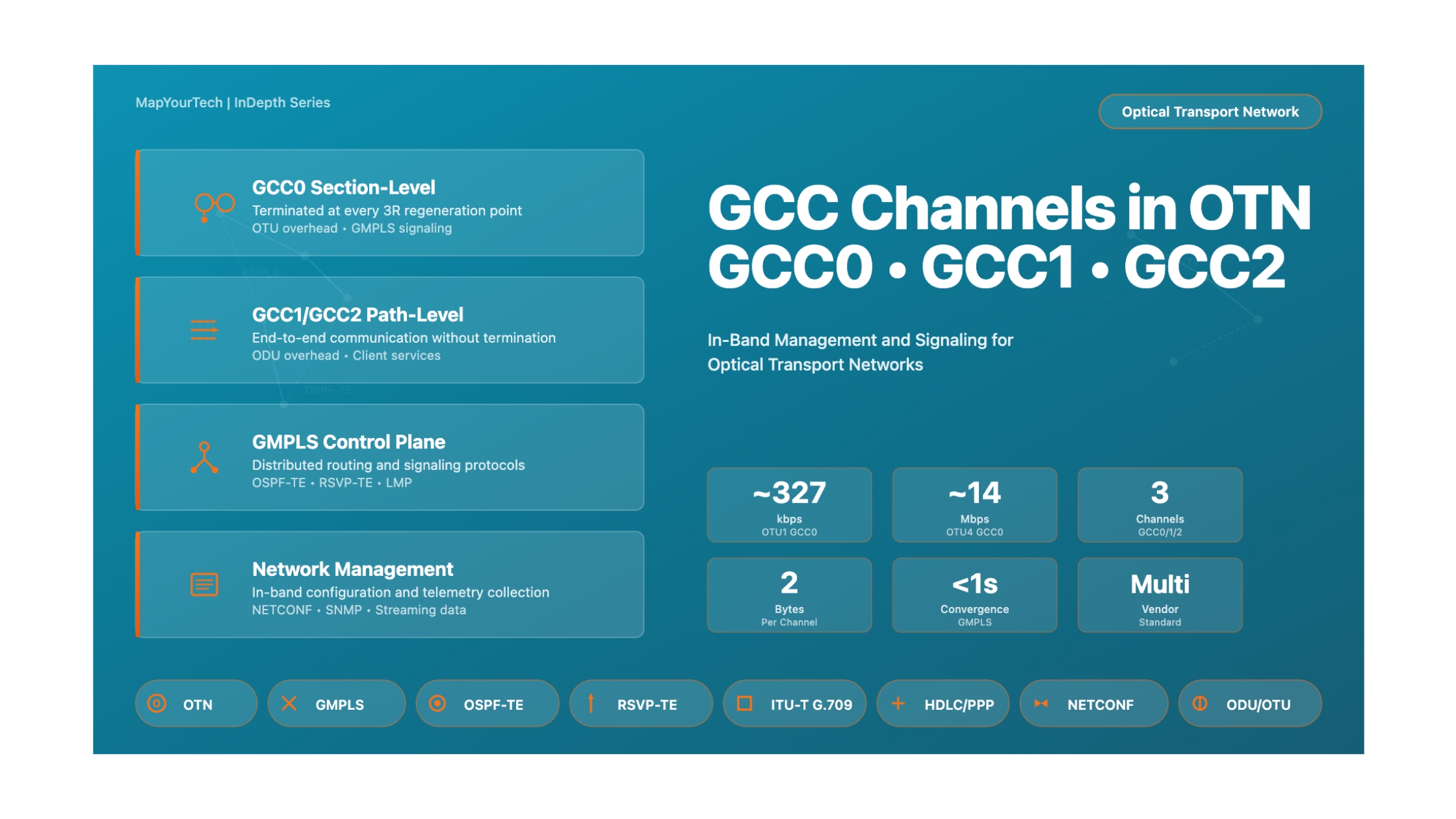
The ITU-T G.709 standard defines three distinct GCC channels—GCC0, GCC1, and GCC2—each occupying specific positions within the OTN frame hierarchy and serving different operational purposes. GCC0 operates at the OTU (Optical Channel Transport Unit) layer and is terminated at every 3R regeneration point, making it ideal for section-level management and GMPLS signaling. GCC1 and GCC2, located in the ODU (Optical Channel Data Unit) overhead, provide path-level communication channels that can carry client end-to-end information across the entire optical path without intermediate termination.
Understanding GCC channels is essential for network engineers designing, deploying, and operating modern optical transport networks. The bandwidth available on these channels varies with the OTN line rate—for example, GCC0 on OTU1 provides approximately 333 kbps, while on OTU2 it offers around 1.3 Mbps, and on OTU3 it scales to approximately 5.3 Mbps. This scalability ensures that higher-capacity OTN interfaces have proportionally more bandwidth available for management and control plane operations, supporting more complex network automation and monitoring requirements.
Animation 1: GCC Channels System Overview
Complete view of GCC0, GCC1, and GCC2 channels in the OTN frame hierarchy showing their positions and operational layers
GCC0 Channel
Located in OTU overhead (2 bytes). Terminated at every 3R regeneration point. Used for GMPLS signaling and section-level management with bandwidth scaling from ~333 kbps (OTU1) to ~6.8 Mbps (OTU4).
GCC1 Channel
Located in ODU overhead (2 bytes). Provides path-level communication between network elements with ODU frame access. Supports end-to-end management and client-specific signaling.
GCC2 Channel
Located in ODU overhead (2 bytes). Provides a second independent path-level communication channel. Can be combined with GCC1 for higher bandwidth (GCC1+2) when needed.
Historical Context and Evolution
From SONET/SDH to OTN Communication Channels
The concept of in-band management channels in optical networks traces its roots to SONET (Synchronous Optical Network) and SDH (Synchronous Digital Hierarchy) technologies, which employed Data Communication Channels (DCC) for network management and monitoring. SONET/SDH's DCC operated at fixed data rates—192 kbps for the Section DCC and 576 kbps for the Line DCC—providing essential communication paths for Operations, Administration, and Maintenance (OA&M) functions. However, as network speeds increased and optical transport requirements evolved, the fixed bandwidth of DCC channels became a limitation.
The development of OTN in the early 2000s, standardized through ITU-T Recommendation G.709, introduced a revolutionary approach to in-band communication. Rather than fixed-rate channels, OTN's GCC channels scale proportionally with the line rate, ensuring that management bandwidth grows alongside network capacity. The first edition of G.709 in 2001 established the foundation for GCC0, GCC1, and GCC2, recognizing that next-generation optical networks would require more sophisticated management capabilities to support wavelength switching, automatic protection switching, and distributed control planes.
A pivotal moment in GCC evolution came with the integration of GMPLS protocols in the mid-2000s. GMPLS required reliable, low-latency communication channels for distributed routing and signaling, and GCC0 emerged as the preferred transport mechanism for these control plane protocols. The ITU-T G.7714.1 recommendation, published in 2005, specifically addressed the use of GCC channels for GMPLS and automatic discovery, establishing standardized encapsulation methods and ensuring interoperability across multi-vendor networks.
Animation 2: Evolution Timeline of Communication Channels
Historical progression from SONET/SDH DCC to modern OTN GCC channels
Key Milestones and Technological Breakthroughs
The evolution of GCC channels has been marked by several critical milestones. The 2009 update to G.709 (version 3.0) introduced support for OTU4 (100G) interfaces, with GCC0 bandwidth scaling to approximately 6.8 Mbps—sufficient to support sophisticated control plane operations and comprehensive network monitoring. This version also refined the frame structure to accommodate higher-order ODU multiplexing, ensuring that GCC1 and GCC2 channels maintained their end-to-end integrity even in complex hierarchical OTN networks.
The introduction of FlexO in the 2016 G.709 update (version 5.0) presented new challenges and opportunities for GCC channels. FlexO's bonding of multiple OTU lanes required careful consideration of how GCC channels would operate across aggregated links. The solution involved combining GCC instances from multiple lanes, providing aggregate bandwidth that scales with the number of bonded lanes—for example, an OTUCn with n lanes provides n times the base GCC bandwidth, supporting even more demanding management and control requirements.
Looking toward the future, GCC channels continue to evolve to meet emerging network requirements. Modern optical networks increasingly deploy Software-Defined Networking (SDN) controllers and programmable interfaces, which rely heavily on GCC channels for southbound communication with network elements. The bandwidth scaling of GCC channels positions them well for these applications, though emerging requirements for real-time telemetry and machine learning-based network optimization are driving discussions about enhanced GCC capabilities in future G.709 revisions.
Future Trajectory
As optical networks scale to 800G, 1.6T, and beyond, GCC channels will continue to provide proportionally higher bandwidth for management and control functions. Current research explores enhanced encapsulation methods, priority-based queuing for GCC traffic, and integration with emerging network automation frameworks. The fundamental architecture of GCC channels—embedded overhead scaling with line rate—remains sound and adaptable to future optical transport requirements.
Core Concepts and Fundamentals
OTN Frame Structure Overview
To understand GCC channels, it is essential to grasp the hierarchical structure of OTN frames. The OTN defines three primary frame types: OPU (Optical channel Payload Unit), ODU (Optical channel Data Unit), and OTU (Optical channel Transport Unit). These frames are nested within each other, with the OPU carrying client data, the ODU adding path monitoring and management overhead, and the OTU providing section monitoring and Forward Error Correction (FEC). GCC channels reside in the overhead portions of the OTU and ODU frames, occupying specific byte positions within the 4-row by 3,824-column frame structure.
Each OTN frame consists of 16 bytes of overhead followed by a payload area. The overhead is organized into four rows, with each row containing specific management, monitoring, and communication fields. The Frame Alignment Signal (FAS) and Multiframe Alignment Signal (MFAS) occupy the first columns, enabling receivers to identify frame boundaries and synchronize with the incoming signal. GCC channels are positioned after these alignment signals, ensuring that frame synchronization is established before GCC communication begins.
Animation 3: OTN Frame Structure with GCC Channel Positions
Detailed view of OTU and ODU frame structures showing exact byte positions of GCC0, GCC1, and GCC2
GCC0: Section-Level Communication
GCC0 occupies two bytes (columns 11 and 12) in the first row of the OTU overhead. These bytes are transmitted in every OTU frame, which occurs at a rate determined by the OTU level—for example, OTU2 frames are transmitted every 48.97 microseconds, and OTU3 frames every 125 microseconds. This high frame rate, combined with two bytes per frame, results in substantial bandwidth scaling with the line rate. The 2-byte GCC0 field provides 16 bits of information per frame, and when multiplied by the frame rate, yields the characteristic GCC0 bandwidth for each OTU level.
The defining characteristic of GCC0 is its termination at every 3R regeneration point. When an OTN signal passes through a 3R regenerator (which performs re-amplification, re-shaping, and re-timing), the entire OTU frame is terminated and regenerated, including the GCC0 channel. This section-level termination makes GCC0 ideal for communicating between adjacent network elements, supporting functions like automatic neighbor discovery, section-level fault management, and GMPLS routing protocols that require hop-by-hop communication.
GMPLS signaling represents one of the most important applications of GCC0. The OSPF-TE (Open Shortest Path First - Traffic Engineering) and RSVP-TE (Resource Reservation Protocol - Traffic Engineering) protocols used in GMPLS networks require low-latency, reliable communication between adjacent optical switches. GCC0 provides this communication path without requiring separate management network infrastructure. Protocol packets are encapsulated using standard methods defined in ITU-T G.7714.1, typically using HDLC (High-Level Data Link Control) or PPP (Point-to-Point Protocol) framing, and transmitted through the GCC0 bytes.
GCC0 Bandwidth Calculation
The bandwidth of GCC0 scales with the OTU line rate according to the formula:
GCC0_Bandwidth = (2 bytes/frame) × (8 bits/byte) × (Frame_Rate)

Where:
  Frame_Rate = Line_Rate / (4 rows × 4080 columns × 8 bits/byte)

Examples:
  OTU1 (2.666 Gbps): 2.666×10⁹ / (4×4080×8) = 20,420 frames/sec
  GCC0_BW = 2 × 8 × 20,420 = 326,723 bps (~327 kbps)

  OTU2 (10.709 Gbps): 10.709×10⁹ / (4×4080×8) = 82,025 frames/sec
  GCC0_BW = 2 × 8 × 82,025 = 1,312,405 bps (~1.31 Mbps)

  OTU3 (43.018 Gbps): 43.018×10⁹ / (4×4080×8) = 329,491 frames/sec
  GCC0_BW = 2 × 8 × 329,491 = 5,271,864 bps (~5.27 Mbps)

  OTU4 (111.81 Gbps): 111.81×10⁹ / (4×4080×8) = 856,388 frames/sec
  GCC0_BW = 2 × 8 × 856,388 = 13,702,208 bps (~13.7 Mbps)
GCC1 and GCC2: Path-Level Communication
GCC1 and GCC2 reside in the ODU overhead, specifically in row 4, columns 1-2 (GCC1) and columns 3-4 (GCC2). Unlike GCC0, these channels are not terminated at 3R regeneration points. Instead, they provide end-to-end communication between network elements that have access to the ODU frame structure—typically at the originating and terminating endpoints of an optical path. This end-to-end property makes GCC1 and GCC2 ideal for client-specific management, service-level monitoring, and applications requiring continuous communication across multiple network segments.
The availability of two independent path-level GCC channels (GCC1 and GCC2) provides flexibility in network design. These channels can be used independently for different management domains—for example, one carrier might use GCC1 for its internal management while preserving GCC2 for customer-specific applications. Alternatively, both channels can be combined (GCC1+2) to provide double the bandwidth when higher-capacity communication is needed. The ITU-T G.709 standard explicitly supports this combined mode, allowing network operators to adapt the GCC configuration to their specific requirements.
In hierarchical ODU multiplexing scenarios, where lower-order ODU signals are multiplexed into higher-order ODU signals, the GCC1 and GCC2 channels of the client ODU are preserved and transported transparently through the network. This ensures that client-specific management information remains intact even when signals traverse multiple network domains. For instance, an ODU2 client signal multiplexed into an ODU3 carrier will maintain its GCC1/GCC2 content throughout the transport path, enabling true end-to-end management visibility.
Animation 4: GCC0 Section-Level vs GCC1/GCC2 Path-Level Operation
Illustrating the fundamental difference in termination behavior between GCC0 and GCC1/GCC2 channels
Technical Architecture and Components
Protocol Stack and Encapsulation
GCC channels transport management and signaling information using standardized encapsulation protocols. The most common approach follows ITU-T G.7714.1, which defines Generic Framing Procedure (GFP) based encapsulation or HDLC/PPP framing for GCC communication. For GMPLS applications, OSPF-TE and RSVP-TE protocol packets are encapsulated using standard IP/Ethernet framing, then mapped into the GCC byte stream. This layered approach ensures that higher-level protocols remain independent of the physical GCC transport mechanism.
The protocol stack typically consists of four layers: the Physical Layer (GCC bytes in OTN overhead), the Data Link Layer (HDLC/PPP or GFP framing), the Network Layer (IPv4/IPv6 for GMPLS), and the Application Layer (OSPF-TE, RSVP-TE, SNMP, or proprietary management protocols). Each network element implementing GCC communication includes a GCC termination function that extracts bytes from incoming frames, reconstructs the protocol data units, and forwards them to the appropriate protocol handler. This architecture enables flexible deployment of various management and control applications over a common GCC transport infrastructure.
Animation 5: GCC Protocol Stack Architecture
Layered protocol architecture showing encapsulation from application protocols down to GCC bytes
Data Flow and Processing
Within a network element, GCC data flows through multiple processing stages. In the transmit direction, application-layer protocols generate management or signaling messages that are passed to the network stack. The IP layer adds addressing information, the data link layer performs framing and adds error detection codes, and finally the GCC termination function inserts the resulting byte stream into the appropriate GCC overhead positions in outgoing OTN frames. This process must occur within strict timing constraints to ensure that GCC bytes are available for each frame transmission.
In the receive direction, the process reverses. The GCC termination function extracts GCC bytes from incoming OTN frames, buffers them, and performs frame delineation based on the data link protocol in use. Valid frames are passed to the network layer for IP processing, and ultimately to the application layer where GMPLS protocols or management applications process the received information. Error detection and correction at each layer ensures robust communication even in the presence of bit errors or temporary signal impairments.
Animation 6: GCC Signal Flow Through Network Element
Complete signal processing path from incoming optical signal to protocol handling and back
Bandwidth Scaling and Performance
The bandwidth available on GCC channels directly impacts the performance of management and control plane operations. Higher bandwidth enables more frequent updates, supports larger routing tables, allows for richer telemetry data collection, and reduces latency in protection switching coordination. As OTN line rates have scaled from OTU1 (2.66 Gbps) to OTU4 (111.8 Gbps) and beyond to FlexO implementations, GCC bandwidth has scaled proportionally, ensuring that management capabilities keep pace with network capacity growth.
| OTU Level | Line Rate | Frame Rate | GCC0 Bandwidth | GCC1 Bandwidth | GCC2 Bandwidth | GCC1+2 Combined |
|---|---|---|---|---|---|---|
| OTU1 | 2.666 Gbps | 20,420 fps | ~327 kbps | ~327 kbps | ~327 kbps | ~654 kbps |
| OTU2 | 10.709 Gbps | 82,025 fps | ~1.31 Mbps | ~1.31 Mbps | ~1.31 Mbps | ~2.62 Mbps |
| OTU2e | 11.095 Gbps | 85,008 fps | ~1.36 Mbps | ~1.36 Mbps | ~1.36 Mbps | ~2.72 Mbps |
| OTU3 | 43.018 Gbps | 329,491 fps | ~5.27 Mbps | ~5.27 Mbps | ~5.27 Mbps | ~10.54 Mbps |
| OTU4 | 111.810 Gbps | 856,388 fps | ~13.70 Mbps | ~13.70 Mbps | ~13.70 Mbps | ~27.40 Mbps |
Performance Calculation: GMPLS Update Interval
The GCC bandwidth determines how frequently GMPLS protocols can exchange updates. For OSPF-TE link state advertisements:
Max_Update_Rate = GCC_Bandwidth / (LSA_Size + Overhead)

Example for OTU2 (GCC0 = 1.31 Mbps):
  LSA_Size = 200 bytes (typical)
  Overhead = 50 bytes (IP/HDLC headers)
  Total_Packet = 250 bytes = 2000 bits

  Max_Update_Rate = 1,310,000 bps / 2000 bits
                    = 655 LSAs per second

For a network with 50 nodes, each with 10 links:
  Total_Links = 50 × 10 = 500 links
  Update_per_Link = 655 / 500 = ~1.3 updates/sec/link

This allows sub-second convergence for topology changes!
Types, Variations, and Classifications
GCC Operation Modes
GCC channels can operate in several distinct modes depending on network requirements and equipment capabilities. The primary distinction is between "transparent" and "terminated" modes. In transparent mode, a network element forwards GCC bytes from input to output without processing them—this is common in simple regenerators or wavelength converters that don't participate in control plane operations. In terminated mode, the network element extracts and processes GCC content, potentially generating new GCC traffic based on local management or control plane protocols.
Transparent Mode
Characteristics: GCC bytes pass through unchanged. No protocol processing occurs at the network element.
Use Cases: Optical amplifiers, passive optical multiplexers, wavelength converters without management capability.
Advantages: Minimal equipment complexity, preserves end-to-end GCC communication.
Terminated Mode
Characteristics: GCC content is extracted, processed, and new GCC traffic is generated for output.
Use Cases: ROADM nodes, OTN switches, 3R regenerators participating in GMPLS.
Advantages: Enables hop-by-hop signaling, section-level management, and distributed control.
Hybrid Mode
Characteristics: Some GCC channels terminated (e.g., GCC0) while others pass through (e.g., GCC1/2).
Use Cases: 3R regenerators supporting GMPLS (terminate GCC0) while preserving client GCC (pass GCC1/2).
Advantages: Optimal for layered network architectures with multiple management domains.
GCC Channel Combinations
The ITU-T G.709 standard defines several ways to utilize GCC channels, either independently or in combination. GCC1 and GCC2 can be used as two separate 2-byte channels, providing independent communication paths for different applications or management domains. Alternatively, they can be combined into a single GCC1+2 channel with 4 bytes per frame, effectively doubling the available bandwidth. This combined mode is particularly useful for applications requiring higher data rates, such as comprehensive performance monitoring or real-time telemetry collection.
Animation 7: GCC Channel Combination Modes
Three operational modes showing GCC1 and GCC2 used separately or combined
Practical Applications and Case Studies
GMPLS Signaling and Routing
One of the most important applications of GCC0 is supporting GMPLS (Generalized Multi-Protocol Label Switching) control plane operations in optical networks. GMPLS extends traditional MPLS concepts to optical transport networks, enabling dynamic provisioning, automated protection switching, and distributed traffic engineering. The control plane consists of several protocols: OSPF-TE for topology discovery and dissemination, RSVP-TE for signaling and label distribution, and Link Management Protocol (LMP) for link verification and fault management.
In a GMPLS-enabled OTN network, each optical switch discovers its neighbors using GCC0-transported LMP hello messages. Once adjacencies are established, OSPF-TE runs over GCC0, exchanging link state advertisements that describe the network topology, available bandwidth, protection capabilities, and other traffic engineering parameters. When a new connection request arrives, the ingress node computes a path through the network and uses RSVP-TE signaling over GCC0 to establish the end-to-end optical path. This hop-by-hop signaling reserves resources at each intermediate node, configures cross-connections, and establishes the optical channel.
Case Study 1: Continental Carrier GMPLS Deployment
Scenario: A Tier-1 carrier operates a 40-node OTN network spanning 8,000 km across North America, using OTU3 interfaces (43 Gbps) with GCC0 bandwidth of approximately 5.3 Mbps per link.
GMPLS Implementation:
- OSPF-TE running on GCC0 for topology distribution across all 40 nodes
- RSVP-TE for dynamic ODU2 and ODU3 provisioning
- LMP for automated neighbor discovery and fault correlation
- Average LSA size: 180 bytes, propagated to all nodes within 500ms of topology change
Performance Results: With 5.3 Mbps GCC0 bandwidth, the network achieved sub-second convergence for single link failures, supporting ~2,900 LSA updates per second. Dynamic circuit provisioning completed in under 3 seconds end-to-end, with RSVP-TE path messages traversing up to 12 hops. The network successfully handled 50 simultaneous provisioning requests without GCC congestion.
Key Learnings: GCC0 bandwidth at OTU3 rate (5.3 Mbps) proved sufficient for networks up to 50-60 nodes. Larger networks would benefit from OTU4 interfaces (~13.7 Mbps GCC0) or implementation of OSPF area hierarchies to reduce routing overhead.
Animation 8: GMPLS Signaling Over GCC0
Complete GMPLS control plane operation showing neighbor discovery, topology exchange, and path signaling
Network Management Applications
Beyond GMPLS, GCC channels support a wide range of network management applications. Simple Network Management Protocol (SNMP) is commonly transported over GCC channels, enabling centralized network management systems to poll device status, collect performance metrics, and configure network elements. Modern implementations increasingly use NETCONF/YANG for configuration management, providing more structured and programmable interfaces for network automation. The bandwidth available on GCC channels—particularly when using GCC1+2 combined mode or higher-rate OTU interfaces—enables rich telemetry collection including per-wavelength power levels, pre-FEC bit error rates, and detailed alarm histories.
Case Study 2: Data Center Interconnect with GCC-Based Management
Scenario: A cloud service provider operates five data centers interconnected by OTN using OTU4 interfaces (111.8 Gbps), with GCC0 bandwidth of 13.7 Mbps and combined GCC1+2 bandwidth of 27.4 Mbps per ODU4 path.
Management Architecture:
- GCC0: Used for inter-DC GMPLS control plane (OSPF-TE, RSVP-TE)
- GCC1: Dedicated to NETCONF/YANG configuration management
- GCC2: Used for streaming telemetry (performance monitoring data)
- Each DC hosts 20 OTN transponders with 100G client interfaces
Telemetry Implementation: Using GCC2's 13.7 Mbps bandwidth, the network collects comprehensive performance data every 100ms: pre-FEC BER, post-FEC BER, Q-factor, chromatic dispersion, polarization mode dispersion, optical power (Tx/Rx), and temperature. This high-frequency monitoring enables machine learning algorithms to predict failures 2-4 hours before they occur, achieving 99.999% service availability.
Key Benefits: The in-band management over GCC eliminated the need for separate management networks, reducing capital costs by 15% and operational complexity significantly. The high GCC bandwidth at OTU4 rates enabled real-time network visibility that would have been impractical with lower-rate interfaces or out-of-band management networks.
Troubleshooting and Best Practices
Common GCC Issues and Resolutions
Issue 1: GCC Link Failure Alarms
Symptom: Network management system reports "GCC Link Fail" or "GCC Communication Loss" alarms.
Root Causes:
- Bit errors in GCC overhead bytes due to poor OSNR or dispersion
- Frame delineation loss in HDLC/GFP protocol
- IP configuration mismatch or routing issues
- Protocol timeout (LMP hello interval exceeded)
Resolution Steps:
- Check physical layer: Verify OSNR > 15 dB, dispersion within limits, no FEC errors
- Verify GCC is enabled on both ends of the link
- Check IP addressing and subnet masks on GCC interfaces
- Review protocol timer settings (LMP, OSPF hello intervals)
- Monitor GCC byte error counters—consistent errors indicate overhead corruption
Issue 2: GMPLS Routing Instability
Symptom: Frequent OSPF adjacency flaps, inconsistent topology database, slow convergence times.
Root Causes:
- GCC bandwidth insufficient for network size (too many LSAs)
- Packet loss on GCC channel due to congestion
- Timer mismatches between OSPF neighbors
Resolution Steps:
- Calculate required GCC bandwidth: (Number of links × LSA size × update frequency)
- Consider OSPF area hierarchies for networks > 50 nodes
- Implement OSPF update rate limiting to prevent GCC congestion
- Verify OSPF dead interval = 4 × hello interval
- Monitor GCC utilization—sustained > 80% indicates capacity issue
Design Best Practices
Capacity Planning
Calculate required GCC bandwidth based on network size, protocol overhead, and management application requirements. Rule of thumb: GMPLS networks with 30+ nodes benefit from OTU3 (5.3 Mbps GCC0) or higher.
Redundancy Design
Ensure GCC communication paths have redundancy. For critical GMPLS networks, design topology such that every node has at least two independent GCC0 paths to avoid control plane partitioning.
Security Considerations
Implement authentication for GMPLS protocols (OSPF-TE, RSVP-TE) to prevent unauthorized topology manipulation or resource hijacking. MD5 authentication is minimum; IPsec preferred for high-security environments.
Monitoring and Visibility
Deploy comprehensive monitoring of GCC channel health: byte error rates, link utilization, protocol message rates, and latency. Set thresholds for proactive alarming before service-affecting issues occur.
Protocol Optimization
Tune GMPLS protocol timers based on network size and GCC bandwidth. Larger networks benefit from longer OSPF hello intervals and higher LSA refresh timers to reduce protocol overhead.
Future-Proofing
Reserve one GCC channel (e.g., GCC2) for future applications. As networks evolve toward more automation and telemetry, having spare GCC capacity enables graceful introduction of new management capabilities.
Conclusion
General Communication Channels (GCC0, GCC1, and GCC2) represent a fundamental innovation in optical transport networking, providing scalable, in-band communication capabilities that enable sophisticated network management and control plane operations. Unlike their fixed-bandwidth predecessors in SONET/SDH networks, GCC channels scale proportionally with OTN line rates, ensuring that management and control capabilities keep pace with network capacity growth from 2.5 Gbps to 100 Gbps and beyond.
The strategic positioning of GCC channels within the OTN frame hierarchy—GCC0 in the OTU overhead for section-level communication and GCC1/GCC2 in the ODU overhead for path-level communication—enables flexible deployment models that support both hop-by-hop signaling protocols like GMPLS and end-to-end management applications. This architectural elegance has proven remarkably adaptable, supporting use cases ranging from traditional network element management to modern SDN controllers and machine learning-based network optimization.
As optical networks continue to evolve toward higher capacities, software-defined architectures, and increased automation, GCC channels will remain a cornerstone of in-band network communication. The bandwidth scaling inherent in the OTN design ensures that future 400G, 800G, and 1.6T interfaces will provide proportionally greater GCC capacity, supporting ever more sophisticated control plane protocols, real-time telemetry collection, and distributed network intelligence. For network engineers and architects, understanding GCC channels is essential for designing, deploying, and operating modern optical transport infrastructure.
Key Takeaways
Essential Points to Remember
- GCC0 (2 bytes in OTU overhead) is terminated at every 3R point and ideal for section-level management and GMPLS signaling
- GCC1/GCC2 (2 bytes each in ODU overhead) provide end-to-end path-level communication without intermediate termination
- GCC bandwidth scales with line rate: ~327 kbps at OTU1 to ~13.7 Mbps at OTU4 per 2-byte channel
- GMPLS protocols (OSPF-TE, RSVP-TE, LMP) commonly use GCC0 for distributed control plane operations
- GCC1 and GCC2 can operate independently or be combined (GCC1+2) for double bandwidth
- Protocol encapsulation typically uses HDLC/PPP or GFP with IP networking for GMPLS applications
- GCC capacity planning should account for network size, protocol overhead, and future management requirements
- Modern applications extend beyond GMPLS to include NETCONF/YANG configuration management and streaming telemetry
- FlexO and OTUCn interfaces aggregate multiple lanes, providing proportionally scaled GCC bandwidth
- Security best practices include protocol authentication (MD5 minimum, IPsec preferred) and access control
Future Developments
The evolution of GCC channels continues as optical networks advance toward higher capacities and increased automation. Current research and standardization activities focus on several key areas: enhanced encapsulation methods to support more efficient protocol multiplexing, priority-based queuing mechanisms to ensure critical GMPLS signaling receives preferential treatment during congestion, and integration with emerging network automation frameworks including YANG-based programmable interfaces and intent-based networking systems.
The convergence of optical networking with cloud-native architectures and distributed computing paradigms presents new opportunities for GCC channel utilization. Future applications may include distributed machine learning inference at network elements, blockchain-based service verification, and quantum key distribution for enhanced security—all requiring the reliable, scalable in-band communication that GCC channels provide.
References
[1] ITU-T Recommendation G.709, "Interfaces for the optical transport network (OTN)" .
[2] ITU-T Recommendation G.7714.1, "Discovery and LMP in the automatically switched optical network" .
[3] ITU-T Recommendation G.874, "Management aspects of optical transport network elements" .
[4] RFC 3945, "Generalized Multi-Protocol Label Switching (GMPLS) Architecture" .
[5] RFC 4204, "Link Management Protocol (LMP)," October 2005.
[6] OIF Implementation Agreement, "OIF-ENNI-OTNv3-AM-01.0," Optical Internetworking Forum".
[7] IEEE 802.3, "Ethernet," Institute of Electrical and Electronics Engineers.
[8] Sanjay Yadav, "Optical Network Communications: An Engineer's Perspective" – Bridge the Gap Between Theory and Practice in Optical Networking.
[9] Huub van Helvoort, "The ComSoc Guide to Next Generation Optical Transport,"`.
[10] ITU-T Supplement 56, "OTN transport of CPRI signals".
For educational purposes in optical networking and DWDM systems
Note: This guide is based on industry standards, best practices, and real-world implementation experiences. Specific implementations may vary based on equipment vendors, network topology, and regulatory requirements. Always consult with qualified network engineers and follow vendor documentation for actual deployments.
Feedback Welcome: If you have any suggestions, corrections, or improvements to propose, please feel free to write to us at [email protected]

Optical Communications & Network Automation Expert | Author of 3 Books for Optical Engineers | Founder, MapYourTech
Optical networking engineer with nearly two decades of experience across DWDM, OTN, coherent optics, submarine systems, and cloud infrastructure. Founder of MapYourTech. Read full bio →
Follow on LinkedIn