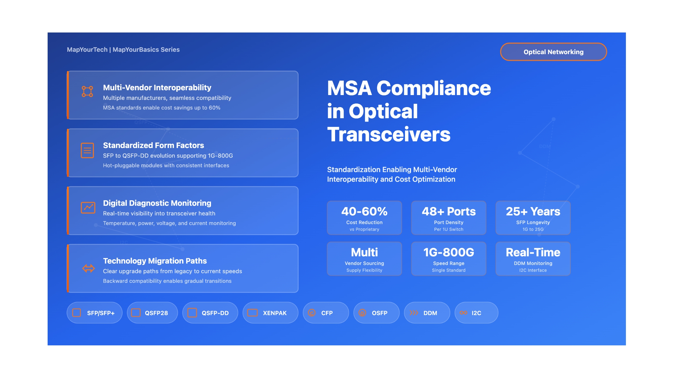

MSA Compliance in Optical Transceivers: Why Standards Are Essential
A Comprehensive Guide to Multi-Source Agreements, Interoperability Benefits, and Vendor Compatibility in Modern Optical Networks
Introduction
In modern optical networking, the ability to mix and match components from different vendors is not just a convenience—it is a fundamental requirement for building cost-effective, scalable, and maintainable network infrastructure. Multi-Source Agreements (MSAs) make this interoperability possible by defining standardized specifications for optical transceivers that allow products from multiple manufacturers to work seamlessly together. As we progress through 2026, understanding MSA compliance has become even more critical for network engineers, system architects, and procurement professionals who need to make informed decisions about optical transceiver selection and deployment in an era of 400G/800G mainstream deployment and emerging 1.6T technologies.
MSAs emerged in the late 1990s and early 2000s as the optical networking industry recognized the need for standardized form factors, electrical interfaces, and mechanical specifications. Before MSAs, network operators were often locked into single-vendor ecosystems, facing higher costs, longer lead times, and limited flexibility. Today in 2026, MSA-compliant transceivers from dozens of manufacturers can be deployed in the same network, driving competition, reducing costs by 40-60% compared to proprietary alternatives, and accelerating innovation. The success of MSA standardization over three decades has proven the value of industry collaboration in creating open, competitive markets.
This article provides a comprehensive examination of MSA compliance in optical transceivers, covering the evolution of major MSA standards (including GBIC, SFP, QSFP, QSFP-DD, XENPAK, X2, and CFP families), the technical requirements for compliance, interoperability benefits, vendor compatibility considerations, and practical guidance for procurement and deployment. We also explore current developments in 800G deployment and emerging trends in 1.6T, co-packaged optics (CPO), and linear drive optics (LDO) that are shaping the future of optical interconnects. Whether you are new to optical networking or an experienced professional, this guide will help you understand why MSA standards matter and how to leverage them effectively in your network infrastructure.
1. Evolution of MSA Standards
1.1 Historical Context
The concept of Multi-Source Agreements originated from the need to create open, vendor-neutral specifications for optical components. In the early days of optical networking, each equipment manufacturer developed proprietary transceiver modules that could only be used with their own systems. This created several problems including vendor lock-in, high costs, limited supply chain flexibility, and slow innovation cycles. Network operators demanded a better solution, leading to the formation of industry working groups to develop standardized specifications.
The first significant MSA was the GBIC (Gigabit Interface Converter) specification, released in the mid-1990s. GBIC defined a hot-swappable transceiver module for Gigabit Ethernet and Fibre Channel applications. While GBIC represented a major step forward in standardization, its relatively large form factor limited port density on network equipment. This limitation drove the development of smaller, more compact form factors that would eventually become the dominant standards in the industry.
Figure 1: Timeline of major MSA standards evolution showing progression from 1 Gb/s to 800+ Gb/s
1.2 Major MSA Form Factors
The optical transceiver industry has developed several major form factor families, each optimized for different speed grades, power budgets, and application requirements. Understanding these form factors is essential for selecting the right transceiver for your network infrastructure. As of 2026, the industry has largely standardized around the SFP family for lower speeds (1G-25G), the QSFP family for medium to high speeds (40G-400G), and emerging next-generation form factors like QSFP-DD and OSFP for 400G-800G applications. Legacy form factors like GBIC, XENPAK, and X2 have been phased out, while CFP family modules remain in specialized coherent optics applications.
| Form Factor | Introduction Year | Speed Range | Electrical Lanes | Typical Applications | Status |
|---|---|---|---|---|---|
| GBIC | 1995 | 1 Gb/s | 1 | Gigabit Ethernet, Fibre Channel | Legacy |
| SFP | 2001 | 1 Gb/s | 1 | Gigabit Ethernet, 1G Fibre Channel | Mature |
| XENPAK | 2001 | 10 Gb/s | 4 (XAUI) | Early 10G Ethernet | Obsolete |
| X2 | 2002 | 10 Gb/s | 4 (XAUI) | 10G Ethernet, OC-192/STM-64 | Legacy |
| SFP+ | 2006 | 10 Gb/s | 1 | 10G Ethernet, 10G Fibre Channel | Mature |
| QSFP | 2006 | 40 Gb/s | 4 × 10G | 40G Ethernet, InfiniBand QDR | Mature |
| CFP | 2009 | 100 Gb/s | 10 × 10G | 100G Ethernet, OTU4 | Legacy |
| CFP2 | 2013 | 100-200 Gb/s | 4 × 25G | 100G/200G coherent optics | Mature |
| QSFP28 | 2013 | 100 Gb/s | 4 × 25G | 100G Ethernet, EDR InfiniBand | Mature |
| CFP4 | 2014 | 100 Gb/s | 4 × 25G | 100G coherent, dense WDM | Mature |
| SFP28 | 2015 | 25 Gb/s | 1 | 25G Ethernet | Mature |
| QSFP-DD | 2017 | 200-400 Gb/s | 8 × 25G/50G | 200G/400G Ethernet, datacenter | Current |
| QSFP56 | 2017 | 200 Gb/s | 4 × 50G | 200G Ethernet, HDR InfiniBand | Current |
| OSFP | 2017 | 400-800 Gb/s | 8 × 50G/100G | 400G/800G Ethernet, AI/ML | Current |
| QSFP112 | 2023 | 800 Gb/s | 8 × 100G | 800G Ethernet, next-gen datacenter | Current |
Form Factor Status Definitions (2026)
Obsolete: No longer manufactured; replaced by newer technologies (XENPAK)
Legacy: Limited new deployments; existing installations being maintained (GBIC, X2, CFP)
Mature: Widely deployed; stable technology with broad vendor support; continued production (SFP/SFP+, QSFP/QSFP+, QSFP28, CFP2/CFP4)
Current: Active deployment in new networks; current generation for high-speed applications (QSFP-DD, QSFP56, OSFP, QSFP112 for 400G-800G)
2. What is a Multi-Source Agreement (MSA)?
2.1 Definition and Purpose
A Multi-Source Agreement (MSA) is a formal specification developed through collaboration between multiple companies in the optical networking industry. Unlike proprietary standards controlled by a single vendor, MSAs represent consensus-driven specifications that define the mechanical, electrical, and functional characteristics of optical transceiver modules. The primary purpose of an MSA is to enable interoperability—ensuring that modules from different manufacturers can be used interchangeably in the same host equipment without compatibility issues.
MSAs typically define several critical aspects of transceiver design including physical dimensions and mechanical interface specifications (connector types, mounting mechanisms, thermal interfaces), electrical interface specifications (signal levels, timing requirements, power supply voltages), management interface protocols (I2C/MDIO communication, memory maps for configuration and monitoring), optical specifications (wavelength, power levels, receiver sensitivity), and environmental requirements (operating temperature ranges, humidity tolerance, EMI compliance).
The development process for an MSA typically involves formation of a working group with representatives from equipment manufacturers, transceiver vendors, and sometimes network operators. The group develops draft specifications through iterative design reviews and technical discussions, creates reference designs and compliance testing procedures, and eventually publishes the final specification for public use. Importantly, MSAs are typically royalty-free, meaning any manufacturer can implement the specification without paying licensing fees to the MSA member companies.
2.2 MSA Organizational Structure
MSAs are developed by industry working groups that bring together stakeholders from across the optical networking ecosystem. These working groups operate through consensus-building processes where technical decisions are made through discussion and voting among member companies. The organizational structure typically includes a steering committee that sets overall direction, technical subcommittees focused on specific aspects (mechanical, electrical, optical, management), compliance and testing groups that develop test procedures, and documentation teams responsible for maintaining specifications.
Participation in MSA working groups is generally open to any interested company, though some groups may have membership fees or require formal agreements. The collaborative nature of MSA development helps ensure that specifications are practical, implementable, and address real-world deployment needs. This open participation model has been key to the success and widespread adoption of MSA standards across the industry.
3. Technical Requirements for MSA Compliance
3.1 Mechanical Specifications
Mechanical compliance is one of the most fundamental requirements for MSA transceivers. The mechanical specifications ensure that modules from different vendors are physically compatible with host equipment and can be installed without modification. Key mechanical requirements include precise dimensional tolerances (typically within ±0.1mm for critical dimensions), standardized connector types and pin assignments (such as the 38-pin edge connector for QSFP modules or the 20-pin connector for SFP modules), thermal interface specifications defining how heat is transferred from the module to the host system, and mounting mechanisms including latch designs and insertion/extraction force requirements.
The mechanical specifications also define requirements for module strength and durability, including resistance to vibration and shock, mechanical retention force to prevent accidental disconnection, and connector mating cycle specifications (typically 250-500 cycles minimum). These requirements ensure that MSA-compliant modules can withstand the rigors of installation, operation, and maintenance in real-world deployment scenarios.
Figure 2: Generic MSA-compliant transceiver architecture showing TX/RX paths, management interface, and key functional blocks
3.2 Electrical Interface Requirements
The electrical interface specifications define how the transceiver communicates with the host system. MSAs specify detailed requirements for high-speed data lanes including differential impedance (typically 100Ω), signal voltage levels and eye diagram parameters, maximum signal integrity parameters (jitter, rise/fall times), and lane-to-lane skew specifications for multi-lane interfaces. For QSFP28 modules operating at 25 Gb/s per lane, for example, the electrical interface must meet stringent jitter requirements to ensure reliable operation.
In addition to the high-speed data interface, MSAs define a management interface that allows the host system to communicate with the transceiver for configuration, monitoring, and control. The most common management interface is based on I2C (Inter-Integrated Circuit) protocol, operating at 100 kHz or 400 kHz. The MSA specifications define a standardized memory map that includes identification information (vendor name, part number, serial number, date code), capability information (supported speeds, wavelengths, distances), digital diagnostic monitoring data (temperature, voltage, optical powers, currents), and alarm/warning threshold values and flag status.
3.3 Optical Interface Specifications
Optical interface requirements ensure that transceivers can interoperate with fiber infrastructure and with other transceivers in the network. Key optical specifications include operating wavelength and spectral width (for example, 1310 nm ± 20 nm for LR4 transceivers), transmit optical power range (specified as minimum and maximum values in dBm), receiver sensitivity (the minimum optical power required for a specified bit error rate), optical return loss requirements (to minimize reflections), and extinction ratio (the ratio between optical power for logic 1 and logic 0).
For multi-wavelength transceivers such as CWDM (Coarse Wavelength Division Multiplexing) or DWDM (Dense WDM) modules, the MSA specifications define the wavelength grid and channel spacing. For example, QSFP-DD 400G DR4 modules use four wavelengths in the O-band (1271 nm, 1291 nm, 1311 nm, 1331 nm) with approximately 20 nm channel spacing, following the LAN-WDM wavelength grid defined in IEEE 802.3bs.
3.4 Digital Diagnostic Monitoring (DDM)
One of the most valuable features standardized by MSAs is Digital Diagnostic Monitoring, also known as Digital Optical Monitoring (DOM). DDM provides real-time access to critical operating parameters within the transceiver, enabling network operators to monitor transceiver health, detect degradation before failures occur, and troubleshoot link problems more effectively. MSA specifications define standardized memory locations and data formats for DDM parameters.
The core DDM parameters specified in most MSAs include transceiver temperature (typically in degrees Celsius with 1/256°C resolution), supply voltage (typically in volts with 100 µV resolution), transmit bias current for each laser (in milliamps), transmit optical power for each lane (in dBm or µW), and receive optical power for each lane (in dBm or µW). Additionally, MSAs define alarm and warning thresholds for each monitored parameter, with high/low alarm thresholds indicating serious conditions that require immediate attention and high/low warning thresholds indicating conditions approaching alarm levels.
4. Interoperability Benefits of MSA Compliance
4.1 Multi-Vendor Sourcing
Perhaps the most significant benefit of MSA compliance is the ability to source transceivers from multiple vendors. This multi-vendor capability provides several important advantages. Cost optimization through competitive pricing is enabled as multiple vendors compete for business, driving down prices compared to single-source proprietary solutions. Network operators can compare pricing from different vendors and select the most cost-effective options for their specific requirements. Supply chain flexibility and resilience is improved since dependence on a single vendor is eliminated, reducing the risk of supply chain disruptions. If one vendor experiences manufacturing delays or component shortages, alternative sources are readily available.
Reduced vendor lock-in gives network operators more negotiating leverage and the freedom to change vendors without replacing host equipment. This is particularly important for long-term network planning and avoiding obsolescence issues. Faster time to market occurs because proven, standards-compliant modules are available from multiple sources, reducing development time for new equipment. Equipment manufacturers can design systems knowing that multiple transceiver vendors will be able to supply compliant modules, reducing time to market for new products.
4.2 Simplified Network Operations
MSA compliance simplifies many aspects of network operations and maintenance. Standardized form factors mean that spare transceivers can be stocked and used across equipment from different manufacturers, reducing the number of unique SKUs (Stock Keeping Units) that need to be maintained in inventory. This inventory consolidation reduces storage costs, minimizes the risk of stocking obsolete parts, and simplifies inventory management systems.
Field technicians benefit from standardized installation procedures across different transceiver vendors. The installation, removal, and handling procedures are consistent regardless of vendor, reducing training requirements and the risk of installation errors. Troubleshooting is simplified because DDM parameters follow standardized formats, allowing the same monitoring tools and procedures to be used regardless of transceiver vendor. Network management systems can be developed to work with transceivers from any MSA-compliant vendor, reducing software development and maintenance costs.
4.3 Technology Migration Paths
MSA standards provide clear technology migration paths as network requirements evolve. The evolution from SFP to SFP+ to SFP28 illustrates how form factor compatibility can be maintained while increasing data rates from 1G to 10G to 25G. SFP+ modules can typically be used in SFP ports (with reduced functionality), and SFP28 modules are mechanically compatible with SFP+ ports, enabling gradual migrations without wholesale equipment replacements. By 2026, many networks have completed migrations from 10G SFP+ to 25G SFP28 for server connectivity, while maintaining legacy 1G SFP ports for management and out-of-band access.
Similarly, the QSFP family (QSFP, QSFP+, QSFP28, QSFP-DD) has maintained backward compatibility where feasible, allowing newer modules to be used in some older systems. QSFP-DD uses the same basic form factor as QSFP28 but doubles the number of electrical lanes (from 4 to 8) to achieve higher speeds. A QSFP-DD port can accept QSFP28 modules (operating at 100G), providing investment protection. However, QSFP28 ports cannot accommodate the full capabilities of QSFP-DD 400G modules. This backward compatibility has enabled many datacenter operators to deploy QSFP-DD switches in 2024-2026 while gradually transitioning from QSFP28 to QSFP-DD transceivers as higher bandwidth becomes necessary.
The industry has learned from past transitions that form factor longevity is critical. The SFP form factor, introduced in 2001, remained the dominant small form factor for over 25 years, spanning speeds from 1G to 25G. The QSFP form factor, introduced in 2006, has similarly proven adaptable from 40G through 400G (and potentially to 800G with QSFP112). This longevity provides network operators with confidence that investments in switching infrastructure will support multiple generations of transceiver technology, enabling pay-as-you-grow bandwidth scaling strategies.
Figure 3: Physical size comparison and port density analysis for major MSA form factors
5. Vendor Compatibility and Procurement Best Practices
5.1 Understanding Vendor "Compatibility" vs. MSA Compliance
It is important to distinguish between MSA compliance and vendor compatibility. An MSA-compliant transceiver meets the standardized specifications defined by the MSA, ensuring physical, electrical, and functional interoperability with any host equipment designed to the same MSA specification. However, some network equipment vendors implement additional requirements or restrictions that go beyond the MSA specifications, creating vendor-specific compatibility requirements.
Common vendor-specific extensions include enhanced management interface features (proprietary extensions to the I2C memory map for additional monitoring or control capabilities), vendor identification requirements (some equipment checks for specific vendor IDs in the transceiver EEPROM and may restrict functionality if an "approved" vendor is not detected), extended temperature ranges or enhanced environmental specifications beyond MSA baseline requirements, and vendor-specific quality assurance or validation procedures that transceivers must pass to be officially supported.
These vendor-specific requirements can create challenges for network operators who want to leverage multi-vendor sourcing. However, many transceiver manufacturers have developed transceivers that are both MSA-compliant and specifically validated for compatibility with major network equipment vendors. These are often marketed as "compatible with" or "validated for" specific equipment brands. When procuring transceivers, it is important to understand whether strict vendor compatibility is required for warranty support, or whether MSA compliance alone is sufficient for your deployment.
5.2 Codec Compatibility
One important compatibility consideration that often gets overlooked is codec compatibility in the management interface. While the MSA specifications define the I2C protocol and basic memory map structure, they do not always specify every detail of how data is encoded or interpreted. This can lead to compatibility issues where transceivers from different vendors use slightly different conventions for encoding certain parameters.
For example, some transceivers encode optical power measurements using a linear scale (in µW), while others use a logarithmic scale (in dBm). The MSA specifications typically define which approach should be used, but implementations may vary. Similarly, temperature measurements may use different calibration coefficients or may be encoded as signed or unsigned values. Network management systems must account for these variations when interpreting DDM data from transceivers with different codecs.
Most modern network equipment and NMS software handle these codec variations automatically, but it is worth verifying compatibility when deploying transceivers from a new vendor for the first time. Testing DDM functionality and comparing reported values against known-good reference measurements can help identify any codec compatibility issues before wide-scale deployment.
5.3 Procurement and Testing Best Practices
Successful deployment of MSA-compliant transceivers from multiple vendors requires careful procurement and testing procedures. Here are key best practices that have proven effective in real-world deployments.
Vendor Qualification Process
Establish a vendor qualification process that includes verification of MSA compliance through documentation review or third-party testing certifications, compatibility testing in your specific equipment and network environment, optical performance testing (BER testing, link margins, long-term stability), and evaluation of vendor quality systems, warranty terms, and technical support capabilities. Maintain a qualified vendor list and update it periodically as new vendors emerge or existing vendors make product changes.
Sample Testing Before Volume Deployment
Before deploying transceivers from a new vendor in production networks, conduct thorough sample testing including optical parameter verification using optical power meters and bit error rate testers, DDM accuracy validation by comparing reported values against measured values, interoperability testing with your specific equipment models and software versions, environmental testing if your deployment includes harsh environmental conditions, and long-term burn-in testing (typically 72 hours minimum) to identify early failures.
Procurement Strategies
Develop procurement strategies that balance cost optimization with risk management. Consider maintaining relationships with multiple qualified vendors to enable competitive sourcing while avoiding the risk of quality issues from unknown vendors. Split purchases among multiple vendors to maintain supply chain flexibility rather than relying entirely on the lowest-cost source. Implement lot tracking and quality monitoring procedures to quickly identify any quality issues with specific manufacturing lots. Build appropriate inventory buffers of critical transceiver types to maintain operations during vendor transitions or supply chain disruptions.
Key Takeaways - Procurement Best Practices
- MSA compliance ensures basic interoperability, but verify vendor-specific compatibility requirements
- Establish a vendor qualification process with sample testing before volume deployment
- Maintain relationships with multiple qualified vendors for supply chain resilience
- Implement lot tracking and quality monitoring to quickly identify any issues
- Balance cost optimization with risk management—don't rely solely on lowest-cost sourcing
6. Common Deployment Scenarios and Use Cases
6.1 Datacenter Networking
Datacenters represent one of the largest deployment scenarios for MSA-compliant transceivers. The scale of modern hyperscale and cloud datacenters—often involving hundreds of thousands or even millions of transceiver ports—makes multi-vendor sourcing essential for cost management and supply chain flexibility. Typical datacenter deployment scenarios as of 2026 include top-of-rack (ToR) switches increasingly using QSFP28 (100G) transceivers to connect servers to the network fabric, with leading-edge deployments beginning to adopt 200G connections, spine switches predominantly using QSFP-DD (400G) transceivers for aggregation and core connectivity, with early adoption of 800G in the largest hyperscale facilities, and storage networks using specialized transceivers for Fibre Channel (32G/64G) or high-speed Ethernet storage protocols.
MSA compliance enables datacenter operators to source transceivers from multiple vendors, driving competitive pricing and ensuring supply availability even during periods of high demand or component shortages. The component shortages of 2021-2023 demonstrated the critical value of multi-vendor sourcing strategies. The standardized DDM interface is particularly valuable in datacenter environments, where automated monitoring and management of hundreds of thousands of transceivers is essential for maintaining network health and identifying problems proactively. By 2026, most large datacenters have implemented sophisticated monitoring systems that leverage MSA-standardized DDM data to predict failures, optimize network performance, and automate capacity planning.
6.2 Enterprise Campus Networks
Enterprise campus networks typically use MSA-compliant transceivers for building-to-building connections, datacenter interconnects within a campus, and connections between distribution and access layers. Common form factors in enterprise deployments include SFP for 1G connections (still widely deployed for desktop connectivity and access layer uplinks), SFP+ for 10G connections (distribution layer and server connectivity), and QSFP+ or QSFP28 for 40G/100G connections (core backbone and high-performance computing clusters).
The ability to source MSA-compliant transceivers from multiple vendors is particularly valuable for enterprise networks, where IT budgets are often constrained and equipment lifecycles are long. Enterprises benefit from the flexibility to upgrade portions of their network incrementally using newer transceiver types while maintaining compatibility with existing infrastructure. The standardized form factors also simplify spare parts management and reduce the complexity of inventory management across multiple buildings or campus locations.
6.3 Telecommunications Service Provider Networks
Service providers deploy MSA-compliant transceivers in access networks for fiber-to-the-home and business services, metro networks for aggregation and transport, and long-haul networks for core backbone connectivity. While service provider networks traditionally relied more heavily on vendor-specific equipment due to advanced features and carrier-grade requirements, the industry has increasingly embraced MSA standards to reduce costs and increase supply chain flexibility.
Service providers particularly value the standardization of coherent optical transceivers in CFP2 and CFP4 form factors, which enable high-capacity long-haul transmission using advanced modulation formats and DSP-based impairment compensation. The ability to source these expensive, high-performance transceivers from multiple vendors provides significant cost savings and supply chain benefits for large-scale network deployments.
7. Future Trends in MSA Development
7.1 800G and Beyond
The optical transceiver industry continues to push toward higher speeds to meet insatiable bandwidth demands from cloud computing, artificial intelligence, and video streaming. The 800 Gb/s generation is now in widespread deployment across hyperscale datacenters using form factors such as QSFP-DD (with 8 lanes at 100 Gb/s per lane using PAM4 modulation), QSFP112 (standardized 800G solution achieving commercial maturity in 2024-2025), OSFP (optimized for higher power consumption of 800G modules with enhanced cooling), and CFP2-DCO (for coherent 800G applications in datacenter interconnect and metro networks). These modules represent the current generation of high-speed optical transceivers and have overcome significant technical challenges including electrical signaling at 100+ Gb/s per lane, thermal management of 15-20W modules, and maintaining signal integrity in compact form factors.
Looking beyond 800G, the industry is actively developing 1.6 Tb/s standards with early deployments expected in 2027-2028. The technical roadmap includes increasing lane speeds to 200 Gb/s using more advanced modulation formats like PAM6 or coherent modulation, developing new packaging and thermal management technologies to handle power dissipation approaching 25-30W, exploring co-packaged optics approaches where optical components are integrated directly with switch ASICs, and investigating new optical interconnect architectures for AI/ML clusters. These developments require new MSA specifications that address the unique challenges of ultra-high-speed optical transmission in compact, pluggable form factors while managing unprecedented power and thermal constraints.
7.2 Co-Packaged Optics (CPO)
Co-packaged optics represents a significant shift in transceiver architecture that has gained substantial momentum from 2024-2026. Rather than using pluggable modules, CPO integrates optical components directly onto the switch or router circuit board, immediately adjacent to the switching ASIC. This approach offers several demonstrated benefits including elimination of high-speed electrical traces between ASIC and transceiver, reducing signal integrity challenges and power consumption by 30-40%, higher integration density enabling more ports per switch (demonstrated in early deployments), and potentially 20-30% lower overall system cost through integration and volume manufacturing at scale.
As of 2026, CPO has moved from research labs to early commercial deployments, particularly in hyperscale datacenter environments. Several challenges are being actively addressed through ongoing standardization efforts. These include serviceability models since optical components cannot be easily replaced like pluggable modules (though entire optical engine modules can be swapped), manufacturing yield optimization and reliability validation over multi-year lifecycles, and the development of interoperability standards being driven by the Optical Internetworking Forum (OIF) and specialized CPO working groups. Major switch ASIC vendors have announced CPO-ready silicon, and optical engine suppliers are ramping production. While pluggable optics will remain dominant for most applications through 2028, CPO is expected to capture 15-20% of the hyperscale datacenter market by 2027-2028, particularly for the highest-density, highest-speed applications.
7.3 Linear Drive Optics (LDO) and Improved Power Efficiency
Power consumption has become a critical concern as transceiver speeds increase. A 400G QSFP-DD module typically consumes 12-14W, and 800G modules consume 15-20W or more. When multiplied across thousands of ports in a large datacenter, transceiver power consumption represents a significant operational expense and cooling challenge—often accounting for 15-20% of total network power consumption. Linear Drive Optics (LDO) has emerged as a proven technology that reduces power consumption by eliminating or simplifying the DSP (Digital Signal Processing) functions in the transceiver, achieving power reductions of 25-35% compared to traditional DSP-based modules.
In LDO implementations that achieved commercial deployment in 2024-2025, many DSP functions are moved to the host ASIC, which implements them more power-efficiently due to advanced semiconductor process technology (5nm or 3nm processes vs. 16nm or 28nm in standalone transceiver DSPs). By 2026, LDO has been standardized for several key applications including 400G-DR4 and 400G-FR4 interfaces with broad vendor support, 800G-DR8 and 800G-SR8 with multiple vendors shipping products, and early 1.6T implementations under development. This required standardization of new electrical interfaces between host and transceiver through MSA working groups, including definitions of the electrical signals, timing requirements, and management protocols. The success of LDO demonstrates how MSA standardization continues to evolve to address emerging requirements like power efficiency while maintaining the interoperability benefits that the industry depends upon.
8. MSA Compliance Testing and Certification
8.1 Compliance Testing Procedures
Verifying MSA compliance requires comprehensive testing across multiple domains. Mechanical compliance testing verifies dimensional accuracy using precision measurement equipment, connector pin assignment and mating force testing, and thermal interface verification. Electrical compliance testing includes verification of signal integrity parameters (eye diagrams, jitter, voltage levels), management interface protocol compliance (I2C timing, memory map implementation), and power consumption measurements under various operating conditions.
Optical compliance testing is particularly critical and includes verification of transmit optical power and spectral characteristics, receiver sensitivity measurements at specified bit error rates, and optical return loss and extinction ratio measurements. Environmental testing verifies operation across the specified temperature range, humidity tolerance, and electromagnetic compatibility (EMC) compliance. These tests are typically performed using specialized test equipment including oscilloscopes with high-bandwidth sampling, optical spectrum analyzers, bit error rate testers (BERT), and environmental chambers for temperature and humidity testing.
8.2 Third-Party Testing and Certification
While transceiver manufacturers perform their own compliance testing, third-party testing and certification programs provide independent verification of MSA compliance. Several organizations offer testing and certification services including the Ethernet Alliance, which operates plugfests and interoperability testing events, the University of New Hampshire Interoperability Lab (UNH-IOL), which provides comprehensive testing services for optical transceivers, and various regional testing organizations that specialize in specific markets or technologies.
Third-party certification can provide valuable assurance to network operators and equipment manufacturers that transceivers meet MSA specifications. However, it is important to understand the scope and limitations of any certification. Some programs test only basic compliance with mechanical and electrical specifications, while others include comprehensive interoperability testing with equipment from multiple vendors. The most rigorous programs include long-term reliability testing and environmental stress testing beyond the basic MSA requirements.
8.3 In-House Testing and Validation
Many network operators and equipment manufacturers perform their own testing and validation beyond relying solely on vendor claims or third-party certifications. A basic in-house testing program might include optical power measurements using calibrated power meters, link quality testing using equipment in your specific configuration, DDM accuracy verification by comparing reported values with measured values, and environmental testing if deployment conditions are particularly challenging.
More comprehensive testing programs may include bit error rate testing over extended periods (days to weeks) to verify link stability, optical spectrum analysis to verify wavelength and spectral purity, and interoperability testing with equipment from multiple vendors in your network environment. While in-house testing requires investment in test equipment and expertise, it provides the highest level of confidence that transceivers will perform reliably in your specific deployment scenarios.
9. Challenges and Limitations of MSA Compliance
9.1 Gray Market and Counterfeit Concerns
The widespread adoption of MSA standards and the resulting commoditization of optical transceivers has created a substantial gray market and, unfortunately, a counterfeit market. Gray market transceivers are genuine products that are sold through unauthorized channels, often at discounted prices. While gray market products may be fully functional and MSA-compliant, they may not come with manufacturer warranties or technical support, and their sourcing and handling history may be unknown.
Counterfeit transceivers are a more serious concern. These are products that falsely claim to be from reputable manufacturers or that falsely claim MSA compliance without actually meeting the specifications. Counterfeit transceivers can cause serious problems including unreliable operation and higher failure rates, potential damage to host equipment, lack of proper safety certifications, creating potential hazards, and invalid warranty claims that go unresolved.
Protecting against gray market and counterfeit products requires careful supplier qualification and due diligence. Purchase from reputable suppliers with established relationships and quality assurance programs. Verify product authenticity through manufacturer serial number verification programs where available. Perform sample testing of new procurement batches to verify performance characteristics. Be suspicious of prices that are significantly below market rates, as this may indicate gray market or counterfeit products. Implement lot tracking so that any problems can be traced to specific batches.
9.2 Quality Variation Among Vendors
While MSA compliance ensures that transceivers meet minimum specifications for interoperability, there can be significant quality variation among different manufacturers. Factors that may vary even among compliant transceivers include component quality and manufacturing processes affecting long-term reliability, optical margin above minimum specifications affecting link performance in challenging conditions, environmental robustness beyond baseline MSA requirements, and consistency of performance across production lots.
Not all MSA-compliant transceivers are created equal. Transceivers from tier-one manufacturers often command premium prices not just because of brand recognition, but because they consistently deliver superior quality, reliability, and performance margins compared to lower-cost alternatives. Network operators must balance cost considerations against quality and reliability requirements for their specific applications. Mission-critical links may justify premium transceivers, while less critical connections may be acceptable candidates for lower-cost alternatives provided they are from qualified vendors with proven track records.
9.3 Keeping Pace with Technology Evolution
The rapid pace of technology evolution in optical networking creates challenges for MSA development and standardization. By the time an MSA specification is finalized and products reach volume production, the industry may already be working on the next generation of technology. This can create periods of fragmentation where early products for new speed grades lack standardized specifications, forcing equipment manufacturers and network operators to work with proprietary solutions or pre-standard implementations.
The transition to 400G provides a clear historical example—from 2017-2019, multiple competing form factors and approaches were available before the industry coalesced around QSFP-DD and OSFP as the dominant standards by 2020-2021. Similarly, the current 800G transition (2024-2026) has seen QSFP-DD, QSFP112, and OSFP competing for market share, with different vendors and application segments favoring different solutions. During such transition periods, procurement decisions become more challenging, and there is risk of investing in technologies that may not align with eventual standards. The 800G market is now stabilizing in 2026, with QSFP-DD dominating datacenter applications and OSFP capturing a significant share in AI/ML cluster deployments requiring higher power budgets.
Looking ahead to 1.6T deployment (expected 2027-2029), network architects should stay engaged with industry forums and standards bodies, monitor technology roadmaps from major equipment vendors and silicon suppliers, maintain flexibility in network architecture to accommodate multiple form factor options, and plan for gradual transitions rather than wholesale technology replacements. The lesson from previous transitions is that standardization takes 2-3 years from initial product availability to industry-wide consensus, and early adopters must carefully evaluate the trade-offs between performance benefits and interoperability risks.
10. Conclusion
Multi-Source Agreements have fundamentally transformed the optical networking industry by establishing standardized specifications that enable interoperability, multi-vendor sourcing, and competitive markets. As we move through 2026, MSA compliance provides numerous proven benefits including cost optimization through competitive pricing (typically 40-60% savings vs. proprietary solutions), supply chain flexibility and resilience (critically important during the component shortages of 2021-2023), simplified network operations and maintenance across multi-vendor environments, clear technology migration paths from legacy to current and next-generation speeds, and significantly reduced vendor lock-in.
However, successfully leveraging MSA standards requires understanding the nuances of compliance versus compatibility, implementing proper vendor qualification and testing procedures, balancing cost optimization with quality and reliability requirements, and staying informed about emerging standards and technology evolution. The future of MSA development through 2027-2030 will continue to address the challenges of ever-increasing speeds (1.6T and beyond), dramatically improved power efficiency through technologies like LDO, new architectures such as co-packaged optics gaining commercial traction, and AI/ML-optimized optical interconnects for training clusters.
For network engineers, system architects, and procurement professionals in 2026, MSA compliance is not just a technical specification—it is a proven strategic enabler of flexible, cost-effective network infrastructure. By understanding MSA standards and implementing appropriate procurement and testing practices, organizations can build robust, high-performance optical networks that leverage the benefits of multi-vendor sourcing while managing the associated risks and challenges. As optical networking continues to evolve toward 1.6T, 3.2T, and beyond, MSA standards will remain essential to enabling innovation while maintaining the interoperability that the industry depends upon. The success of MSA standardization over the past 30 years demonstrates the value of industry collaboration in creating open, competitive markets that benefit all stakeholders.
Summary - Why MSA Compliance Is Essential in 2026
- MSA standards enable multi-vendor interoperability, driving cost reductions of 40-60% compared to proprietary solutions
- Standardized form factors simplify network operations, reduce inventory complexity, and provide clear technology migration paths from 1G to 800G+
- Digital diagnostic monitoring (DDM) provides valuable real-time visibility into transceiver health and performance across all vendors
- 800G transceivers are now in widespread deployment with mature MSA standards (QSFP-DD, QSFP112, OSFP)
- Emerging technologies like LDO (25-35% power savings) and CPO are being standardized for 1.6T and beyond
- Successful deployment requires vendor qualification, sample testing, and ongoing quality monitoring programs
References
1. SFF Committee, "QSFP+ 28 Gb/s 4X Pluggable Transceiver Solution (QSFP28)," SFF-8665
2. SFF Committee, "Small Form Factor Pluggable (SFP) Transceiver Multi-Source Agreement (MSA)," SFF-8472
3. X2 MSA Group, "X2 10 Gigabit Small Form Factor Pluggable Module"
4. XENPAK MSA Group, "10 Gigabit Ethernet XENPAK Multi-Source Agreement"
5. CFP MSA, "C Form-factor Pluggable Multi-Source Agreement Hardware Specification"
6. CFP4 MSA, "CFP4 Hardware Specification"
7. IEEE 802.3, "Ethernet Standards Including 10GBASE, 40GBASE, 100GBASE, and 400GBASE specifications"
8. ITU-T Recommendation G.709, "Interfaces for the Optical Transport Network (OTN)"
9. Sanjay Yadav, "Optical Network Communications: An Engineer's Perspective" – Bridge the Gap Between Theory and Practice in Optical Networking
Developed by MapYourTech Team
For educational purposes in Optical Networking Communications Technologies
Note: This guide is based on industry standards, best practices, and real-world implementation experiences. Specific implementations may vary based on equipment vendors, network topology, and regulatory requirements. Always consult with qualified network engineers and follow vendor documentation for actual deployments.
Feedback Welcome: If you have any suggestions, corrections, or improvements to propose, please feel free to write to us at [email protected]

Optical Communications & Network Automation Expert | Author of 3 Books for Optical Engineers | Founder, MapYourTech
Optical networking engineer with nearly two decades of experience across DWDM, OTN, coherent optics, submarine systems, and cloud infrastructure. Founder of MapYourTech. Read full bio →
Follow on LinkedIn