
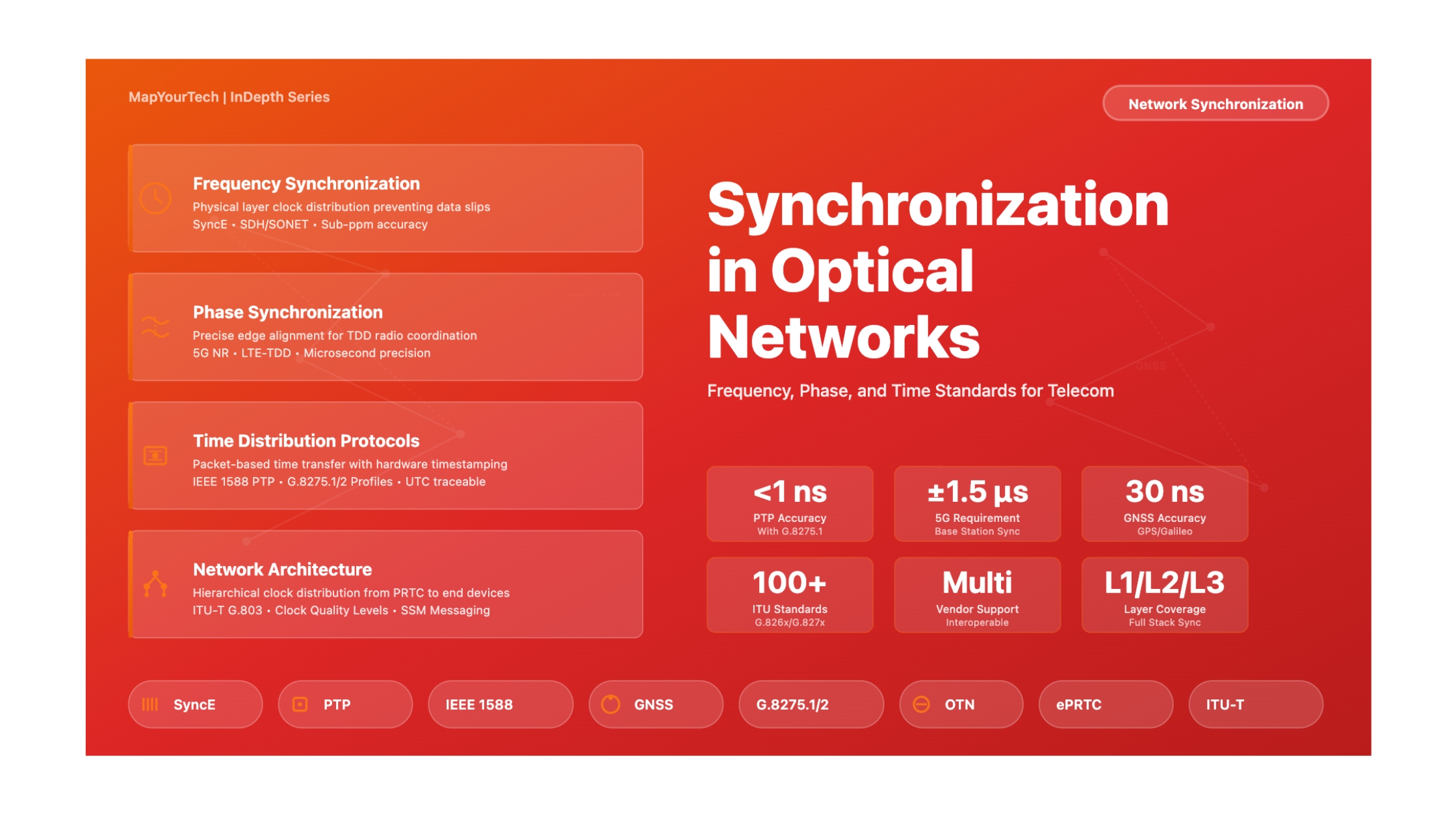
Synchronization in Optical Networks: A Comprehensive Deep Dive
Exploring Frequency, Phase, and Time Synchronization Standards for Modern Telecommunication Networks
1. Introduction
Modern optical networks form the backbone of global telecommunications, carrying massive volumes of data across continents at the speed of light. Behind this seamless connectivity lies a fundamental requirement that often goes unnoticed: precise synchronization. Network synchronization ensures that all equipment operates with aligned clock rates and timing, which is essential for maintaining quality of service, preventing data loss, and enabling advanced applications.
The importance of synchronization in optical networks cannot be overstated. Without proper synchronization, network elements would operate at slightly different frequencies, leading to buffer overflows or underflows, resulting in data slips that corrupt voice calls, video streams, and data transfers. In the traditional circuit-switched telephone network, even a small frequency mismatch of a few parts per million could cause service interruptions. Today, with the advent of 5G networks, precision time coordination, and financial trading systems, the requirements have become even more stringent, demanding nanosecond-level accuracy.
Synchronization in telecommunications operates at three distinct levels, each serving different purposes and applications. Frequency synchronization ensures all network clocks tick at the same rate, preventing gradual drift that would cause buffer issues in Time Division Multiplexing systems. Phase synchronization aligns the precise timing of clock edges, critical for applications like 5G Time Division Duplex radio, where transmit and receive windows must be coordinated to within microseconds across multiple base stations. Time-of-day synchronization provides absolute UTC time information, necessary for log correlation, billing systems, regulatory compliance, and distributed database consistency.
This article provides an in-depth exploration of synchronization standards and technologies deployed in optical networks. We examine the evolution from legacy Time Division Multiplexing networks to modern packet-based synchronization, analyze the technical architecture of clock hierarchies, and detail implementation methods including Synchronous Ethernet, Precision Time Protocol, and satellite-based timing systems. Through this comprehensive analysis, network engineers and architects will gain the knowledge needed to design, deploy, and troubleshoot synchronization solutions that meet the demanding requirements of contemporary telecommunications infrastructure.
2. Historical Context: Evolution of Network Synchronization
2.1 The Era of TDM Synchronization
The history of network synchronization begins with the deployment of digital telephone networks in the 1960s and 1970s. Early Plesiochronous Digital Hierarchy networks operated with nominally synchronized clocks running at nearly the same frequency, but not precisely locked together. Each network node maintained its own independent clock, leading to occasional timing slips when data was transferred between nodes with slightly different clock rates. To accommodate these frequency variations, network equipment included elastic buffers that could absorb small timing differences, but these buffers would eventually overflow or underflow, causing audible clicks in voice calls.
The introduction of Synchronous Digital Hierarchy in Europe and Synchronous Optical Network in North America represented a significant advancement. These technologies mandated that all network elements derive their timing from a common master clock source, typically a Primary Reference Clock based on atomic frequency standards. SDH and SONET networks employed a hierarchical synchronization architecture where timing flowed from primary reference sources through successive levels of network equipment. Each intermediate node would recover the clock signal from incoming optical or electrical interfaces and use this synchronized clock to generate outgoing signals, creating a chain of timing distribution across the entire network.
Within SDH and SONET frames, overhead bytes carried Synchronization Status Messages that indicated the quality level of the timing source feeding each network element. This messaging system allowed automatic selection of the best available timing reference and prevented timing loops that could destabilize the network. Equipment was classified into stratum levels, with Stratum 1 representing atomic clock accuracy and lower strata providing progressively relaxed specifications suitable for different positions in the timing hierarchy. This architecture proved highly reliable and formed the foundation for telephone network timing that persists in many networks today.
2.2 The Packet Network Challenge
The transition from circuit-switched TDM networks to packet-switched IP and Ethernet networks introduced fundamental challenges for synchronization. Traditional Ethernet was designed with asynchronous operation in mind, where each device maintained an independent transmit clock with accuracy requirements of only ±100 parts per million. Packet networks introduced variable delay as packets traverse switching fabric, wait in queues, and experience different processing times at each hop. This Packet Delay Variation made it extremely difficult to extract precise timing information from packet arrivals.
Mobile network evolution drove the need for packet network synchronization. Second and third generation cellular systems required frequency synchronization at base stations to prevent interference between channels, which could be provided through GPS receivers or by carrying timing over leased TDM circuits. However, as mobile operators migrated their backhaul infrastructure from TDM to packet-based Ethernet and IP networks, they needed methods to deliver synchronization over packet connections. The challenge intensified with 4G LTE Time Division Duplex deployments, which required both frequency and phase alignment to coordinate uplink and downlink transmission windows across multiple cell sites.
This timing crisis spurred the development of new synchronization technologies adapted to packet networks. The telecommunications industry realized that simply relying on Network Time Protocol, which was designed for loose synchronization of computer systems, would not meet the stringent requirements of carrier-grade networks. Two complementary approaches emerged: enhancing the physical layer of Ethernet to carry frequency synchronization similar to SDH, and developing sophisticated packet-based protocols capable of achieving microsecond and eventually nanosecond accuracy despite the challenges of variable network delay.
Read the Full Analysis with Premium
The remaining 89% of this article — the design numbers, trade-offs and field guidance — is part of MapYourTech Premium, along with the full premium library, courses and professional tools.
You May Also Like

-
Free
-
September 4, 2026

-
Premium
-
September 4, 2026

-
Premium
-
September 4, 2026