20 min read
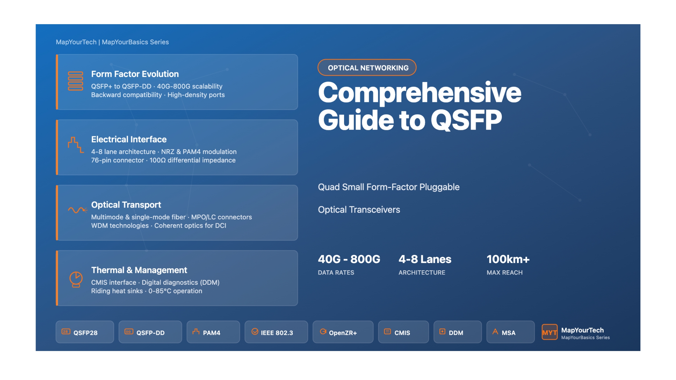
Comprehensive Guide to QSFP Technology
Introduction
The Quad Small Form-Factor Pluggable (QSFP) family represents a critical evolution in high-speed optical transceiver technology for data centers, telecommunications networks, and enterprise infrastructure. These hot-pluggable transceivers provide high-density, high-performance connectivity solutions for modern optical fiber communication networks.
QSFP transceivers combine four independent electrical channels into a single compact form factor, enabling scalable bandwidth from 40 Gbps to 1.6 Tbps through successive generations. The technology supports multiple protocols including Ethernet, InfiniBand, Fibre Channel, and SONET/SDH, making it versatile across various network architectures.
The QSFP family has evolved through several generations, each offering increased data rates while maintaining backward compatibility where possible. This document provides comprehensive technical information about QSFP technology, covering specifications, applications, thermal management, and implementation considerations.
QSFP Family Evolution
QSFP+ (Original Quad Small Form-Factor Pluggable)
The original QSFP+ module supports 4 lanes of 10 Gbps transmission for a total aggregate bandwidth of 40 Gbps. It was designed as a high-density alternative to parallel optics solutions, providing compact form factor suitable for switches and routers.
Data Rate
40 Gbps aggregate (4 × 10 Gbps)
Electrical Interface
4 lanes at 10 Gbps NRZ
Power Consumption
Typically 1.5-3.5W
Connector
38-pin edge connector
QSFP28 (28 Gbps per Lane)
QSFP28 increases the per-lane data rate to 25 Gbps using Non-Return-to-Zero (NRZ) modulation, achieving 100 Gbps aggregate bandwidth. This generation became the workhorse for 100 Gigabit Ethernet deployments.
Data Rate
100 Gbps aggregate (4 × 25 Gbps)
Electrical Interface
4 lanes at 25 Gbps NRZ
Standards
IEEE 802.3bm, SFF-8665
Applications
100GbE, 4×25G Ethernet
QSFP56 (56 Gbps per Lane)
QSFP56 adopts PAM4 (4-level Pulse Amplitude Modulation) signaling to achieve 50 Gbps per lane, supporting 200 Gbps aggregate bandwidth while maintaining the 4-lane architecture.
Data Rate
200 Gbps aggregate (4 × 50 Gbps)
Modulation
PAM4 (50G per lane)
Key Innovation
PAM4 signaling doubles bandwidth
Applications
200GbE, Data Center Interconnect
QSFP-DD (Double Density)
QSFP-DD doubles the electrical interface to 8 lanes while maintaining backward compatibility with QSFP28 modules (using 4 of the 8 lanes). This architecture supports 400 Gbps and 800 Gbps transmission rates.
Data Rate Options
400 Gbps (8 × 50 Gbps)
800 Gbps (8 × 100 Gbps)
Electrical Interface
8 lanes, up to 112 Gbps per lane
Connector
76-pin card edge connector
Management
CMIS (Common Management Interface)
QSFP112 (112 Gbps per Lane)
QSFP112 returns to a 4-lane architecture but increases the per-lane rate to 100 Gbps using PAM4 modulation, achieving 400 Gbps aggregate bandwidth with reduced power consumption compared to QSFP-DD.
Data Rate
400 Gbps (4 × 100 Gbps)
Modulation
PAM4 at 112 Gbps per lane
Standards
IEEE 802.3ck, IEEE 802.3db
Form Factor Variants
Type 1, Type 2, Type 2A, Type 2B
Comparison Table
| Module Type | Lanes | Per-Lane Rate | Modulation | Aggregate Rate | Typical Applications |
|---|---|---|---|---|---|
| QSFP+ | 4 | 10 Gbps | NRZ | 40 Gbps | 40G Ethernet, InfiniBand QDR |
| QSFP28 | 4 | 25 Gbps | NRZ | 100 Gbps | 100G Ethernet, InfiniBand EDR |
| QSFP56 | 4 | 50 Gbps | PAM4 | 200 Gbps | 200G Ethernet |
| QSFP-DD | 8 | 50/100 Gbps | PAM4 | 400/800 Gbps | 400G/800G Ethernet, DCI |
| QSFP112 | 4 | 100 Gbps | PAM4 | 400 Gbps | 400G Ethernet, HPC |
Electrical Interface Specifications
Pin Configuration and Functions
QSFP modules utilize a high-density card-edge connector providing both high-speed differential data lanes and low-speed control/monitoring signals. The original QSFP+ employs a 38-pin configuration, while QSFP-DD extends this to 76 pins to accommodate doubled electrical interfaces.
QSFP+ / QSFP28 Pin Assignment (38-pin)
| Pin | Signal | Type | Description |
|---|---|---|---|
| 1, 4, 7, 13, 16, 19, 20, 23, 26, 32, 35, 38 | GND | Ground | Signal and power common reference |
| 2-3, 33-34, 36-37 | Tx2n/p, Tx3n/p, Tx1n/p | CML-I | Transmitter differential data inputs |
| 5-6 | Tx4n/p | CML-I | Transmitter differential data input (lane 4) |
| 8 | ModSelL | LVTTL-I | Module select (active low) |
| 9 | ResetL | LVTTL-I | Module reset (active low) |
| 10 | VccRx | Power | +3.3V receiver power supply |
| 11 | SCL | LVCMOS-I/O | 2-wire serial interface clock |
| 12 | SDA | LVCMOS-I/O | 2-wire serial interface data |
| 14-15, 17-18, 21-22, 24-25 | Rx3p/n, Rx1p/n, Rx2n/p, Rx4n/p | CML-O | Receiver differential data outputs |
| 27 | ModPrsL | LVTTL-O | Module present (active low) |
| 28 | IntL | LVTTL-O | Interrupt signal (active low) |
| 29 | VccTx | Power | +3.3V transmitter power supply |
| 30 | Vcc1 | Power | +3.3V power supply |
| 31 | LPMode | LVTTL-I | Low power mode control |
High-Speed Electrical Characteristics
The high-speed differential data signals employ CML (Current Mode Logic) signaling with 100-ohm differential impedance. All modules feature AC-coupled inputs and outputs to accommodate DC voltage differences between transmitter and receiver circuits.
Key Electrical Parameters
- Differential Impedance: 100 ohms ±10%
- Coupling: AC coupled on both transmit and receive paths
- Signaling: CML (Current Mode Logic) levels
- Data Encoding: NRZ for QSFP+/QSFP28, PAM4 for QSFP56/QSFP-DD/QSFP112
- Jitter Budget: Defined per IEEE 802.3 and application standards
Low-Speed Control Signals
Low-speed control signaling operates using LVCMOS/LVTTL logic levels at the host Vcc voltage. The module incorporates pull-up resistors on SCL and SDA lines to enable multi-drop I2C bus configurations.
Control Signal Functions
ModSelL (Module Select): When asserted low by the host, enables the module to respond to 2-wire serial interface commands. This signal allows multiple modules on a shared I2C bus with individual addressing.
ResetL (Reset): A low level held for the minimum pulse length initiates a complete module reset, returning all settings to default states. The module indicates reset completion via the IntL signal with Data_Not_Ready bit cleared.
LPMode (Low Power Mode): Controls power consumption states. When asserted high, the module may enter reduced power mode with limited functionality. Implementation varies by module type and application.
ModPrsL (Module Present): Pulled low by the module to indicate physical presence in the host connector. This signal allows hot-plug detection.
IntL (Interrupt): The module asserts this signal low to indicate various status conditions requiring host attention, as defined in the memory map.
Power Requirements
QSFP modules operate from a single +3.3V supply with tight regulation requirements. Power consumption varies significantly based on module type, reach, and technology generation.
| Module Type | Typical Power | Maximum Power | Voltage Range |
|---|---|---|---|
| QSFP+ SR4 | 1.5W | 2.5W | 3.135V - 3.465V |
| QSFP+ LR4 | 3.5W | 4.5W | 3.135V - 3.465V |
| QSFP28 100G | 3.5W | 5.5W | 3.135V - 3.465V |
| QSFP-DD 400G | 10-12W | 15W | 3.135V - 3.465V |
| QSFP-DD 400G Coherent | 15-18W | 20W | 3.135V - 3.465V |
| QSFP112 | 10W | 15W | 3.135V - 3.465V |
Host Board Power Supply Filtering
Proper power supply decoupling and filtering are critical for reliable high-speed operation. The host board should implement multi-stage filtering with both bulk and high-frequency capacitors placed close to the module connector.
- Bulk capacitance: 100-220 µF electrolytic or tantalum capacitors
- High-frequency decoupling: 0.1 µF and 0.01 µF ceramic capacitors
- Placement: Capacitors should be located within 10mm of connector pins
- Power planes: Separate analog and digital power planes recommended for sensitive designs
Optical Interfaces and Fiber Types
Connector Types
QSFP modules employ various optical connector types depending on the application and reach requirements. The mechanical interface must ensure proper fiber alignment and minimize insertion loss.
MPO/MTP Connectors (Parallel Optics)
Multi-fiber Push-On (MPO) connectors, also known as MTP (a performance-enhanced variant), provide high-density parallel optical interfaces. These connectors house multiple fibers in a single ferrule, enabling simultaneous transmission across all lanes.
- MPO-12: 12-fiber connector used in 40G and 100G applications
- MPO-16: 16-fiber connector for higher lane count applications
- BiDi MPO-12: Bidirectional transmission using different wavelengths
- Polarity Management: Type A, Type B, and Type C polarity methods ensure proper transmit-receive fiber mapping
LC Duplex Connectors
LC (Lucent Connector or Little Connector) duplex assemblies provide separate transmit and receive fibers in a compact form factor. These connectors are widely used in single-mode applications and offer excellent optical performance.
- Standard LC: Physical Contact (PC) polish for general applications
- UPC LC: Ultra Physical Contact polish for improved return loss
- APC LC: Angled Physical Contact (8-degree angle) for demanding coherent applications
CS Optical Connector
The CS (Consorzio) connector is an emerging high-density optical interface designed for next-generation transceivers. It provides space-efficient connections for advanced applications requiring multiple fiber pairs in compact form factors.
Fiber Types and Applications
Multimode Fiber Applications
Multimode fiber supports short-reach applications within data centers and enterprise networks. The larger core diameter (50 µm or 62.5 µm) enables use of lower-cost VCSEL (Vertical Cavity Surface Emitting Laser) technology.
| Fiber Type | Core/Cladding | Modal Bandwidth | 40G Distance | 100G Distance | 400G Distance |
|---|---|---|---|---|---|
| OM2 | 50/125 µm | 500 MHz·km @ 850nm | 30m | - | - |
| OM3 | 50/125 µm | 2000 MHz·km @ 850nm | 100m | 70-100m | - |
| OM4 | 50/125 µm | 4700 MHz·km @ 850nm | 150m | 100-150m | 100m (SR8) |
| OM5 | 50/125 µm | 4700 MHz·km @ 850/953nm | 150m | 100-150m | 100-150m |
Single-Mode Fiber Applications
Single-mode fiber enables long-reach transmission for data center interconnect, metro, and wide-area networks. The smaller core diameter (9 µm) requires more sophisticated laser sources but provides minimal dispersion and attenuation.
| Application | Wavelength | Modulation | Typical Distance | Use Cases |
|---|---|---|---|---|
| PSM4 | 1310nm (4 lanes) | Direct NRZ | 500m - 2km | Campus interconnect |
| CWDM4 | 1271-1331nm | Direct NRZ | 2km | Data center interconnect |
| LR4 | 1295-1310nm (LAN-WDM) | Direct NRZ | 10km | Metro access |
| ER4 | 1295-1310nm (LAN-WDM) | Direct/External | 40km | Metro aggregation |
| ZR/ZR+ | C-band (1530-1565nm) | Coherent DP-QPSK/16QAM | 80-120km+ | Regional/long-haul |
| OpenZR+ | C-band | Coherent DP-16QAM | Up to 1000km+ | Long-haul IP-over-DWDM |
Wavelength Division Multiplexing
WDM technology combines multiple optical wavelengths onto a single fiber pair, enabling higher capacity without additional fiber infrastructure. QSFP modules implement various WDM approaches.
CWDM (Coarse Wavelength Division Multiplexing)
CWDM uses wider channel spacing (approximately 20nm) to multiplex 4-8 wavelengths. This approach requires less precise temperature control and utilizes uncooled lasers, reducing power consumption and cost.
LAN-WDM (Local Area Network WDM)
LAN-WDM employs four wavelengths spaced at approximately 4.5nm intervals around 1310nm. This specification balances cost and performance for 10km reach applications.
DWDM (Dense Wavelength Division Multiplexing)
DWDM provides the finest wavelength spacing (typically 50 GHz or 100 GHz ITU grid), enabling the highest capacity per fiber. Coherent QSFP-DD modules implement DWDM for data center interconnect and service provider applications.
Thermal Management
Operating Temperature Classifications
QSFP modules are specified for various operating temperature ranges to accommodate different deployment environments. The case temperature measurement point is typically located near the hottest internal component.
| Class | Temperature Range | Typical Environment |
|---|---|---|
| Standard | 0°C to 70°C | Climate-controlled data centers |
| Extended | -5°C to 85°C | Telecom central offices, extended temp data centers |
| Industrial | -40°C to 85°C | Outdoor equipment, harsh environments |
ASHRAE-Based Classifications (Data Center Environments)
For tightly controlled data center environments, alternative temperature classifications align with ASHRAE thermal guidelines. These specify both functional and performance temperature ranges.
| Class | Functional Range | Performance Range |
|---|---|---|
| A1 | 15°C to 62°C | 25°C to 62°C |
| A2 | 10°C to 65°C | 20°C to 65°C |
| A3 | 5°C to 70°C | 15°C to 70°C |
| A4 | 5°C to 75°C | 15°C to 75°C |
Thermal Design Considerations
System-Level Thermal Management
The host system is responsible for controlling module case temperature within specified limits through proper airflow design and heat removal mechanisms. Several factors influence thermal performance:
- Module Density: Up to 36 QSFP-DD modules can be deployed in 1U rack space, requiring careful thermal planning
- Airflow Direction: Front-to-back or side-to-side airflow patterns impact cooling effectiveness
- Ambient Temperature: Inlet air temperature directly affects achievable case temperatures
- Elevation: Higher elevations reduce air density and cooling capacity
QSFP-DD Thermal Innovations
QSFP-DD introduces enhanced thermal management capabilities through riding heat sinks that can be optimized independently of the optical module design.
- Riding Heat Sinks: External heat sinks mount on top of modules, sized according to thermal requirements
- Inter-Module Heat Sinks: Shared heat sinks between adjacent modules improve heat spreading
- Module Type Variants:
- Type 1: Standard form factor (72.4mm length)
- Type 2: Extended length (87.4mm) for additional cooling surface
- Type 2A: Integrated nose heat sink for enhanced cooling
- Type 2B: High-performance heat sink for modules up to 25W
Touch Temperature Requirements
External surfaces must comply with applicable touch temperature standards to prevent user injury during module handling. For surfaces exceeding short-term touch temperature limits, protective handles or guards must prevent direct contact with hot surfaces during removal.
Thermal Testing and Validation
Modules undergo rigorous thermal testing to ensure reliable operation across the specified temperature range. Testing includes thermal cycling, high-temperature operational life testing, and thermal shock to validate mechanical and optical stability.
Management Interface
2-Wire Serial Interface (I2C)
QSFP modules implement a 2-wire serial interface based on I2C protocol for configuration, monitoring, and diagnostic functions. This interface provides access to a comprehensive memory map containing module identification, operating parameters, and real-time diagnostic data.
Interface Specifications
- Protocol: I2C-compatible 2-wire serial interface
- Clock Frequency: Up to 400 kHz (Fast Mode) for QSFP+/QSFP28; 1 MHz maximum for newer generations
- Addressing: Individual modules selected via ModSelL signal
- Pull-up Resistors: Host provides pull-up to Vcc on SCL and SDA lines
Timing Parameters
| Parameter | Symbol | Minimum | Maximum | Unit |
|---|---|---|---|---|
| SCL clock frequency | fSCL | - | 400 kHz | kHz |
| Bus free time | tBUF | 1.3 | - | µs |
| Start condition hold time | tHD:STA | 0.6 | - | µs |
| Data hold time | tHD:DAT | 0 | - | µs |
| Data setup time | tSU:DAT | 100 | - | ns |
Memory Map Architecture
The module memory map provides standardized access to identification, configuration, monitoring, and control functions. Different QSFP generations implement compatible but evolved memory structures.
QSFP+ / QSFP28 Memory Map (SFF-8636)
The legacy QSFP memory map organizes information into lower and upper page structures:
- Lower Page (Addresses 00h-7Fh): Base identification, real-time monitoring, and control functions
- Upper Page 00h: Extended module identification and capabilities
- Upper Page 01h-02h: Threshold settings and control functions
- Upper Page 03h: User-writable EEPROM for custom data
CMIS (Common Management Interface Specification)
QSFP-DD, QSFP56, and QSFP112 modules adopt CMIS, a unified management interface specification supporting advanced features and multiple form factors.
Key CMIS Features
- Unified Memory Map: Common structure across QSFP-DD, OSFP, and other next-generation form factors
- Enhanced Diagnostics: Expanded monitoring capabilities including per-lane parameters
- Advanced Configuration: Support for tunable parameters, application selection, and firmware management
- Module Firmware Update: Standardized mechanism for in-system firmware updates
- Application Selection: Host-configured module applications for multi-rate operation
Digital Diagnostic Monitoring (DDM)
QSFP modules provide extensive real-time monitoring of operational parameters, enabling proactive network management and fault diagnosis.
Monitored Parameters
| Parameter | Granularity | Purpose |
|---|---|---|
| Temperature | Module | Thermal monitoring and management |
| Supply Voltage | Module | Power supply health monitoring |
| TX Bias Current | Per Lane | Laser health and power control verification |
| TX Power | Per Lane | Optical output power monitoring |
| RX Power | Per Lane | Received signal strength indication |
| TX CDR LOL | Per Lane | Transmit clock and data recovery loss of lock |
| RX CDR LOL | Per Lane | Receive clock and data recovery loss of lock |
Alarm and Warning Thresholds
Each monitored parameter includes configurable high and low alarm and warning thresholds. When measured values exceed thresholds, the module asserts appropriate flags and may generate interrupt signals to the host.
- High Alarm: Parameter exceeds critical high threshold
- Low Alarm: Parameter below critical low threshold
- High Warning: Parameter approaching high limit
- Low Warning: Parameter approaching low limit
Applications and Use Cases
Data Center Applications
Spine-Leaf Architectures
Modern data center networks employ spine-leaf topologies requiring high-radix switches with hundreds of ports. QSFP technology enables dense, cost-effective connectivity between spine and leaf switches.
- Leaf-Spine Links: 100G/400G uplinks using QSFP28/QSFP-DD transceivers
- Server Connectivity: Direct-attach copper or short-reach optical links to servers
- Storage Networks: High-bandwidth, low-latency connections to storage arrays
Data Center Interconnect (DCI)
Connecting geographically distributed data centers requires transceivers combining high capacity with extended reach. QSFP-DD coherent modules enable efficient DCI implementations.
Campus DCI
100G/400G PSM4 or CWDM4 modules for 500m-2km distances connecting nearby facilities
Metro DCI
400G LR4/FR4 or ZR modules for 10-80km metro area connections
Regional DCI
400G/800G coherent OpenZR+ modules for 120km+ regional distances
Long-Haul DCI
High-power coherent modules for 1000km+ connections between distant regions
Service Provider Networks
IP-over-DWDM
Service providers are deploying coherent QSFP-DD modules directly in routers, eliminating separate transponder equipment. This architecture reduces cost, space, and power consumption while simplifying operations.
- OpenZR+ Specification: Industry-standard interoperable coherent transceivers for service provider applications
- Multi-Vendor Interoperability: Tested and validated interoperation between different module suppliers
- Flexible Modulation: Adaptive modulation (DP-QPSK to DP-16QAM) optimizes capacity versus reach
- OTN Support: OTN framing and FEC for carrier-grade performance
Metro Access and Aggregation
Metro networks utilize QSFP modules for aggregating traffic from access networks and connecting to core networks. Applications include mobile backhaul, business services, and residential broadband aggregation.
Enterprise Networks
Campus Backbone
Enterprise campus networks employ QSFP transceivers for building-to-building connectivity and core switching infrastructure.
- Building Interconnects: Single-mode fiber links up to 10km connecting campus buildings
- Core Switching: High-density 100G/400G switching fabrics
- Wireless Backhaul: Connecting distributed Wi-Fi controllers and access points
Storage Area Networks (SANs)
High-performance storage networks leverage QSFP technology for Fibre Channel and iSCSI/FCoE implementations requiring low latency and high reliability.
High-Performance Computing (HPC)
HPC clusters demand ultra-low latency, high bandwidth interconnects between compute nodes. QSFP modules enable efficient scaling of compute fabrics.
- InfiniBand: SDR/DDR/QDR/FDR/EDR InfiniBand fabrics using QSFP/QSFP28
- Ethernet HPC: RDMA over Converged Ethernet (RoCE) implementations
- GPU Interconnects: High-bandwidth connections between GPU accelerators
Cloud and Hyperscale
Cloud service providers and hyperscale operators drive QSFP innovation through massive deployments requiring cost optimization and operational efficiency.
- Disaggregated Architectures: Open networking with disaggregated hardware and software
- Active Optical Cables: Simplified cabling using integrated active components
- Breakout Configurations: 1×400G to 4×100G or 8×50G breakouts for flexible connectivity
Industry Standards and Specifications
Multi-Source Agreements (MSAs)
MSAs define mechanical, electrical, and functional specifications ensuring interoperability between modules from different vendors and compatibility with host equipment.
Key QSFP MSAs
- QSFP+ MSA (SFF-8436 / SFF-8665): Original 40G QSFP specification
- QSFP28 MSA (SFF-8665): 100G QSFP28 specification
- QSFP-DD MSA: Double-density 400G/800G specification with backward compatibility
- QSFP112 MSA: 400G specification using 100G per lane signaling
- OSFP MSA: Alternative high-power form factor for 400G/800G
IEEE Standards
The IEEE 802.3 Ethernet Working Group defines physical layer specifications for Ethernet over optical fiber.
| IEEE Standard | Description | Relevance to QSFP |
|---|---|---|
| IEEE 802.3ba | 40 and 100 Gigabit Ethernet | Defines 40GBASE-SR4/LR4/ER4 and 100GBASE-SR10/LR4/ER4 |
| IEEE 802.3bm | 40G/100G over fiber and backplane | Enhanced 100GBASE specifications including CWDM4 |
| IEEE 802.3bs | 200G and 400G Ethernet | Defines 200GBASE and 400GBASE PMD specifications |
| IEEE 802.3cd | 50G, 100G, 200G PAM4 | 50 Gbps per lane PAM4 signaling for 200G/400G |
| IEEE 802.3ck | 100G/200G/400G electrical interfaces | 100 Gbps electrical signaling for QSFP112 |
| IEEE 802.3db | 100G/200G/400G optical | Optical PMDs using 100 Gbps signaling |
OIF (Optical Internetworking Forum)
OIF develops implementation agreements for optical networking technologies, including coherent optics specifications.
- OIF 400ZR: 400G coherent interface for data center interconnect
- OIF CEI-56G-VSR-PAM4: Chip-to-module electrical interface specification
- OIF CEI-112G-VSR-PAM4: 100G per lane electrical specification
OpenZR+ MSA
The OpenZR+ Multi-Source Agreement extends OIF 400ZR with enhanced features for service provider applications, enabling longer reaches and additional functionality beyond basic DCI use cases.
OpenZR+ Key Features
- Extended reach beyond 120km (up to 1000km+ with amplification)
- Support for both Ethernet and OTN protocols
- Higher performance through improved DSP and modulation
- Multi-vendor interoperability validated through plugfests
- Standardized management interface via CMIS
Other Relevant Standards
Fibre Channel
Fibre Channel standards define protocols and physical layers for storage area networks.
- FC-PI-6: 32GFC Fibre Channel physical interface
- FC-PI-7: 64GFC and 128GFC specifications
InfiniBand
InfiniBand Architecture specifications define high-performance interconnects for HPC and storage applications.
- SDR: Single Data Rate (10 Gbps per port)
- DDR: Double Data Rate (20 Gbps per port)
- QDR: Quad Data Rate (40 Gbps per port)
- FDR: Fourteen Data Rate (56 Gbps per port)
- EDR: Enhanced Data Rate (100 Gbps per port)
- HDR: High Data Rate (200 Gbps per port)
SFF Committee Specifications
- SFF-8472: Digital diagnostic monitoring interface
- SFF-8636: Management interface for 4-lane modules and cables
- SFF-8679: QSFP28 base electrical specification
- SFF-8024: Cross-reference code tables
Telcordia / NEBS
Network Equipment Building System (NEBS) requirements ensure telecommunications equipment reliability.
- GR-63-CORE: Physical protection including seismic, temperature, humidity
- GR-1221-CORE: Generic requirements for fiber optic branching components
Implementation Considerations
Host Board Design Guidelines
PCB Layout Recommendations
Proper printed circuit board design is critical for reliable high-speed signal integrity and electromagnetic compatibility.
- Impedance Control: Maintain 100-ohm ±10% differential impedance for high-speed traces
- Trace Length Matching: Match differential pair lengths within ±5 mils; match lane-to-lane lengths within ±250 mils
- Via Optimization: Minimize vias in high-speed signal paths; use back-drilling for through-hole vias
- Ground Planes: Continuous ground plane beneath high-speed signals
- Keep-out Zones: Maintain specified clearances around module connector footprint
Signal Integrity Considerations
High data rates demand attention to transmission line effects, reflections, crosstalk, and jitter accumulation.
- Return Loss: Minimize discontinuities that cause signal reflections
- Insertion Loss: Use low-loss PCB materials for longer trace lengths
- Crosstalk: Adequate spacing between differential pairs (≥3× trace width)
- Jitter Budget: Allocate board jitter within total link jitter budget
Power Supply Design
Stable, low-noise power delivery ensures reliable module operation across temperature and loading conditions.
- Voltage Regulation: ±3.3V ±3% (3.135V - 3.465V) at module pins
- Current Capacity: Support peak inrush current during hot-plug insertion
- Ripple and Noise: Minimize supply voltage ripple and switching noise
- Decoupling: Multi-stage filtering with appropriate capacitor placement
Electrostatic Discharge (ESD) Protection
QSFP modules incorporate ESD protection on all electrical pins, but proper handling procedures remain essential.
ESD Requirements
- High-Speed Pins: ≥1 kV HBM (Human Body Model) per ANSI/ESDA/JEDEC JS-001
- Low-Speed Pins: ≥2 kV HBM for control and monitoring signals
- IEC 61000-4-2: System-level ESD immunity testing requirements
Handling Precautions
- Use ESD wrist straps when handling modules outside protective packaging
- Store modules in ESD-protective bags or containers
- Ground workstations and equipment before module installation
- Avoid touching electrical contacts or optical apertures
Electromagnetic Interference (EMI)
High-frequency signaling generates electromagnetic emissions that must be controlled to meet regulatory requirements.
EMI Mitigation Strategies
- Shielding: All-metal module housing provides electromagnetic shielding
- Gaskets: Conductive gaskets between module and cage ensure EMI seal
- Bezel Integration: Front panel cutouts minimize EMI leakage
- Dust Covers: EMI covers for empty ports maintain shielding integrity
Optical Considerations
Fiber Cleaning and Inspection
Contaminated optical connections cause signal degradation, insertion loss, and potential component damage.
- Inspect fiber end-faces with microscope before connection
- Clean using approved fiber cleaning materials and techniques
- Never look into active optical ports
- Use protective dust caps when modules are disconnected
Optical Safety
QSFP modules may emit invisible infrared radiation. Follow laser safety guidelines and regulations.
Hot-Plug Considerations
QSFP modules support hot-plugging, allowing insertion and removal without powering down the host system.
Insertion Sequence
- Module present detection (ModPrsL asserted)
- Power supply inrush current limiting
- Module initialization and reset completion
- Host reads module identification and capabilities
- Host configures module for desired application
- Link establishment and traffic flow
Hot-Plug Design Requirements
- Controlled Inrush: Limit power supply inrush current to prevent system upset
- Sequenced Connector: Ground pins make contact before power pins
- Debounce: ModPrsL signal debouncing prevents false insertion detection
References and Additional Resources
- IEEE 802.3 Ethernet Working Group - https://www.ieee802.org/3/
- QSFP-DD MSA - http://www.qsfp-dd.com
- Optical Internetworking Forum (OIF) - http://www.oiforum.com
Unlock Premium Content
Join over 400K+ optical network professionals worldwide. Access premium courses, advanced engineering tools, and exclusive industry insights.
Already have an account? Log in here