15 min read

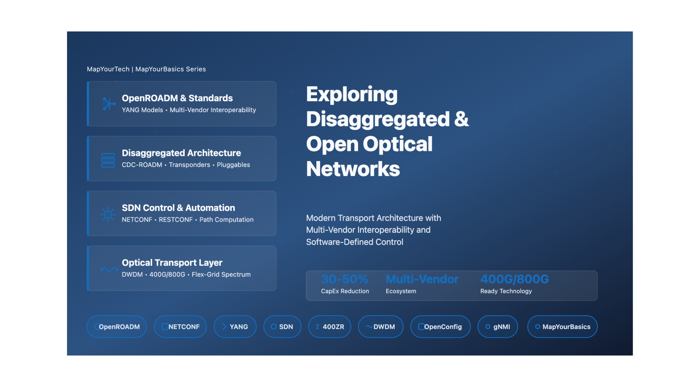
Exploring Disaggregated and Open Optical Networks
A Comprehensive Guide to Modern Optical Transport Architecture
Understanding OpenROADM, SDN Control, Multi-Vendor Interoperability, and Network Automation
Fundamentals & Core Concepts
What are Disaggregated and Open Optical Networks?
Disaggregated and open optical networks represent a fundamental shift in how optical transport infrastructure is designed, deployed, and operated. Unlike traditional vertically integrated solutions where optical hardware and software come from a single vendor, disaggregated networks separate network functions into independent, interoperable components that can be sourced from multiple vendors.
Why Does Disaggregation Occur?
The move toward disaggregation is driven by both technical evolution and market forces:
Technical Drivers
- Standardization Maturity: Development of comprehensive data models (YANG), standardized management protocols (NETCONF, RESTCONF), and open APIs enable interoperability between components from different vendors
- Software-Defined Networking (SDN): SDN architectures separate the control plane from the data plane, allowing centralized management and automation through standardized interfaces
- Modular Hardware Design: Modern optical equipment is designed with functional modularity, enabling colorless, directionless, and contentionless (CDC) ROADM architectures
- Advanced Coherent Technology: Digital signal processing (DSP) advances enable flexible modulation formats and software-configurable transmission parameters
Business Drivers
- Vendor Lock-in Elimination: Traditional proprietary systems limit flexibility and increase costs through single-vendor dependency
- Cost Optimization: Best-of-breed component selection enables operators to optimize capital expenditure (CapEx) and operational expenditure (OpEx)
- Innovation Acceleration: Multi-vendor ecosystems foster rapid technology advancement and competitive pricing
- Operational Flexibility: Disaggregated networks allow operators to deploy new technologies incrementally without forklift upgrades
When Does Disaggregation Matter?
Disaggregation becomes particularly critical in several scenarios:
- Network Expansion: Adding capacity to existing networks while introducing new vendors or technologies
- Technology Refresh: Upgrading transponders to higher speeds (400G, 800G) while retaining existing line systems
- Multi-Domain Operations: Managing optical infrastructure across multiple geographic regions or technology generations
- Alien Wavelength Deployment: Operating transponders from one vendor over another vendor's optical line system
- Cloud/Data Center Interconnect: Implementing IP-over-DWDM architectures with pluggable coherent optics (400ZR/ZR+)
Why is Disaggregation Important?
The practical significance of disaggregation extends beyond cost savings to fundamentally transform how optical networks are designed, deployed, and managed. By breaking down monolithic systems into interoperable components, operators gain unprecedented control over their network infrastructure evolution while fostering a competitive ecosystem that drives continuous innovation.
Mathematical Framework & Technical Parameters
Core Technical Specifications
Open optical networks operate within well-defined technical parameters that ensure interoperability across multi-vendor components. Understanding these specifications is critical for successful network design and deployment.
Fixed Grid (ITU-T G.694.1):
where n = channel number (-96 to +96)
Channel spacing = 50 GHz (0.4 nm @ 1550 nm)
Flexible Grid (ITU-T G.694.1):
where n = frequency slot
Granularity = 6.25 GHz (12.5 GHz for OpenROADM)
Frequency range = 191.325 - 196.125 THz
Link Loss Budget:
= (Distance × Fiber Attenuation) + (N_splices × 0.1 dB) + (N_connectors × 0.5 dB) + 3 dB
Available Margin (dB) = Tx Power - Rx Sensitivity - Total Link Loss
Example Calculation:
Fiber attenuation = 0.2 dB/km
Splices = 8 (@ 0.1 dB each)
Connectors = 4 (@ 0.5 dB each)
Total Loss = (80 × 0.2) + (8 × 0.1) + (4 × 0.5) + 3 = 24.8 dB
Required OSNR:
For 100G DP-QPSK: OSNR_req ≈ 11-13 dB
For 200G DP-16QAM: OSNR_req ≈ 18-20 dB
For 400G DP-16QAM: OSNR_req ≈ 21-23 dB
OpenROADM Technical Parameters
| Parameter | Specification | Description |
|---|---|---|
| Wavelength Range | 96 channels (C-band) | 191.325 - 196.125 THz |
| Grid Type | Fixed/Flexible | 50 GHz fixed or 12.5 GHz flex-grid |
| Tx Power Range | -10 to +2 dBm | Per channel at transponder output |
| Rx Sensitivity | -18 to -28 dBm | Depends on modulation format |
| CD Tolerance | ±60,000 ps/nm | For 100G coherent |
| PMD Tolerance | ≤ 20 ps | Maximum acceptable PMD |
| OSC Channel | 1510 nm / 1625 nm | Optical Supervisory Channel |
| Line Rate | 100G / 200G / 400G | OTU4 / OTUCn format |
Spectrum Utilization Calculations
Example for 400G DP-16QAM:
SE = 400 Gb/s / 75 GHz = 5.33 bits/s/Hz
Frequency Slots Required = ⌈Occupied Bandwidth / 12.5 GHz⌉
For 400G: Slots = ⌈75 GHz / 12.5 GHz⌉ = 6 slots
The flexible grid architecture enables efficient spectrum utilization by allowing channels to occupy only the bandwidth they require, with appropriate guard bands to prevent inter-channel interference. This contrasts with fixed grid systems where all channels occupy uniform 50 GHz slots regardless of actual bandwidth needs.
Types & Components
Disaggregation Architecture Types
1. Fully Disaggregated Architecture
Complete separation of all optical network functions with standardized interfaces between every component:
- ROADM Components: Wavelength Selective Switches (WSS), optical amplifiers, optical multiplexers/demultiplexers from different vendors
- Transponders: Independent coherent transceivers with open interfaces
- Pluggable Optics: Standards-based pluggables (QSFP-DD, OSFP) with interoperable specifications
- SDN Controller: Vendor-neutral management and control platform
- Benefits: Maximum flexibility, best-of-breed selection, competitive pricing
- Challenges: Complex integration, extensive testing requirements, limited vendor accountability
2. Partially Disaggregated Architecture
Selective disaggregation of specific network elements while maintaining integration for others:
- Typical Model: Independent transponders over integrated optical line system (OLS)
- Open Line System: ROADM, amplifiers, and passive components from single vendor
- Alien Wavelengths: Third-party transponders operating over the OLS
- Benefits: Balanced flexibility with reduced complexity, clear vendor responsibilities
- Use Cases: Network expansions, technology refreshes, brownfield deployments
3. Hybrid Architecture
Combination of integrated and disaggregated elements within the same network:
- Metro Networks: Fully disaggregated with rapid technology refresh cycles
- Long-Haul Networks: Partially disaggregated with optimized performance
- Data Center Interconnect: IP-over-DWDM with pluggable coherent optics
- Benefits: Optimized approach for each network segment
Core Network Components
ROADM Component Classification
| ROADM Type | Capabilities | Advantages | Limitations |
|---|---|---|---|
| Colorless (C) | Any wavelength on any add/drop port | Wavelength flexibility, reduced sparing | Wavelength contention possible |
| Directionless (D) | Add/drop port connects to any degree | Route flexibility, simplified planning | Requires additional WSS |
| Contentionless (C) | Same wavelength multiple degrees simultaneously | No blocking, hub configurations | Higher cost, complexity |
| CDC ROADM | All three capabilities combined | Maximum flexibility, future-proof | Highest cost and complexity |
Transponder and Pluggable Classifications
Coherent Transponders
- 100G Transponders: DP-QPSK modulation, 50 GHz spacing, metro/regional applications
- 200G Transponders: DP-8QAM / DP-16QAM, flexible bandwidth, optimized reach vs capacity
- 400G Transponders: DP-16QAM, 75 GHz typical spacing, high-capacity trunk routes
- 800G Transponders: Probabilistic constellation shaping, ultra-high capacity
Pluggable Coherent Optics
- 400ZR: 400G, up to 120 km, standardized (OIF), lower power, router/switch integration
- 400ZR+: 400G, up to 1000+ km, enhanced FEC, vendor-specific features
- 400G-OpenZR+: Multi-vendor interoperability, extended reach, flexible modulation
- 800ZR: Emerging standard for 800G pluggables
Data Model Standards
The component classification and standardization ecosystem enables true multi-vendor interoperability by defining clear boundaries, interfaces, and behaviors for each network element. Success in disaggregated deployments depends on understanding these classifications and selecting the appropriate architecture type for each network segment.
Effects & Impacts
System-Level Effects of Disaggregation
Implementing disaggregated optical networks introduces several system-level effects that impact network design, operations, and performance. Understanding these effects is crucial for successful deployment strategies.
Performance Implications
Quantitative Performance Assessments
| Performance Metric | Traditional Integrated | Disaggregated Network | Impact |
|---|---|---|---|
| CapEx Savings | Baseline | 30-50% reduction | Excellent |
| OpEx (Management) | Single EMS/NMS | +20-40% (w/o automation) | Attention Required |
| OpEx (with SDN) | Baseline | 10-30% reduction | Good |
| Service Provisioning | Days to weeks | Minutes to hours | Excellent |
| Technology Refresh | 3-5 years | 1-2 years | Excellent |
| Integration Time | 2-4 weeks | 4-12 weeks | Longer Timeline |
| Testing Effort | Standard | 2-3x standard | Increased Effort |
| Troubleshooting MTTR | Baseline | +15-30% (multi-vendor) | Moderate Impact |
Tolerance Levels and Thresholds
Power Level Matching:
Per-channel power control: ± 0.5 dB accuracy
Total span OSNR penalty: ≤ 1 dB for alien wavelengths
Timing and Synchronization:
Frame alignment: within 125 µs
FEC convergence: < 500 ms
Impact Severity Classifications
Critical Impact Areas
High Priority- Optical Power Mismatch: Alien transponders with launch powers significantly different from native equipment can cause nonlinear impairments
- FEC Incompatibility: Proprietary FEC schemes prevent interoperability between vendors
- Management Protocol Gaps: Incomplete YANG model support creates operational blind spots
- OSC Channel Conflicts: Different OSC wavelengths or protocols prevent ROADM-to-ROADM communication
Moderate Impact Areas
Medium Priority- Performance Monitoring Gaps: Inconsistent PM data collection across vendors
- Alarm Correlation: Different alarm severity levels and correlation logic
- Software Version Management: Coordinating upgrades across multiple vendors
- Documentation Inconsistencies: Varying levels of API documentation quality
Mitigation Strategies Overview
Understanding and managing these effects is crucial for successful disaggregated network deployments. While challenges exist, they can be effectively mitigated through proper planning, comprehensive testing, robust automation platforms, and well-defined operational procedures. The key is balancing the substantial benefits of disaggregation with realistic assessment of operational complexities.
Techniques & Solutions
Implementation Methods and Approaches
Successful deployment of disaggregated optical networks requires specific technical approaches and implementation strategies that address interoperability, management, and automation challenges.
OpenROADM Implementation Approach
OpenROADM Multi-Source Agreement (MSA)
The OpenROADM MSA provides comprehensive specifications for fully disaggregated optical networks:
- Functional Disaggregation: Defines three core optical functions (pluggable optics, transponder, ROADM) with standardized interfaces
- Device Models: YANG-based device models for configuration, monitoring, and control
- Network Models: Multi-layer topology abstractions (CLLI, OpenROADM, OTN layers)
- Service Models: End-to-end service provisioning and lifecycle management
- Optical Specifications: Single-Wave (W) and Multi-Wave (MW) interface specifications
Advantages:
- Complete optical line system disaggregation capability
- Vendor-neutral management and control
- Mature specifications with real-world deployments
- Comprehensive operational aspects coverage
Disadvantages:
- Complex implementation requirements
- Limited vendor ecosystem compared to OpenConfig
- Challenging to support all vendor-specific capabilities
- Requires significant testing for multi-vendor validation
OpenConfig Approach
OpenConfig provides operational data models with focus on transponder disaggregation:
- Operational Focus: Emphasis on telemetry and streaming data collection
- Transponder Models: Terminal device configuration and monitoring
- gNMI Protocol: gRPC Network Management Interface for efficient data streaming
- Open Line System: Transponder to line system disaggregation
Advantages:
- Broad vendor and operator support
- Excellent streaming telemetry capabilities
- Simpler partial disaggregation model
- Strong cloud/data center operator adoption
Disadvantages:
- Limited full OLS disaggregation support
- Operational aspects require vendor extensions
- Incomplete abstraction for complex ROADM functions
SDN Controller Architecture Solutions
Automation Platform Requirements
Critical Automation Capabilities
- Real-time Inventory Discovery: Automatic discovery and reconciliation of multi-vendor network elements, capturing both physical and logical topology
- Model Abstraction and Translation: Converting between OpenROADM, OpenConfig, T-API, and native vendor models with semantic preservation
- Telemetry Aggregation: Unified collection of streaming telemetry, performance metrics, and alarm data across protocols (NETCONF, gNMI, SNMP)
- Path Computation Engine (PCE): Multi-constraint routing considering OSNR, latency, shared risk groups, and spectrum availability
- Service Orchestration: End-to-end service provisioning with automatic equipment selection and configuration generation
- Closed-loop Automation: AI/ML-driven analytics with automated remediation actions
Alien Wavelength Implementation Techniques
| Technique | Application | Implementation | Considerations |
|---|---|---|---|
| Pre-amplification | Low-power pluggables (400ZR) | EDFA before ROADM multiplexer | Required for ZR/ZR+ integration; adds 1-2 dB OSNR penalty |
| Power Equalization | Mixed vendor transponders | Per-channel VOA adjustment | ±0.5 dB target accuracy; automated control essential |
| Spectral Isolation | Different modulation formats | Guard bands, separate fiber pairs | Reduces nonlinear crosstalk; wastes spectrum |
| Link Budget Margins | Multi-vendor environments | 3-5 dB additional margin | Compensates for interop uncertainties |
| FEC Standardization | Long-haul applications | SD-FEC, oFEC standards | Limits reach vs proprietary FEC |
Best Practices and Recommendations
- Phase 1 - Foundation: Deploy SDN controller with single-vendor network, establish automation workflows and operational procedures
- Phase 2 - Partial Disaggregation: Introduce alien transponders over existing line system, validate interoperability in lab before production
- Phase 3 - Full Disaggregation: Deploy multi-vendor ROADMs and optical components, leverage mature automation platform
- Phase 4 - Optimization: Continuous improvement through telemetry analytics and AI-driven optimization
Real-World Application Scenarios
- Metro/Regional Networks: 400ZR pluggables in routers connected to open line systems for IP-over-DWDM architecture
- Data Center Interconnect: OpenConfig-managed transponders with standardized interfaces for cloud connectivity
- Long-Haul Transport: OpenROADM-compliant components with comprehensive SDN control for nationwide backbone
- Brownfield Upgrades: Adding next-generation transponders (800G) to existing ROADM infrastructure without forklift replacement
- Multi-Domain Networks: Hierarchical SDN controllers with T-API northbound for cross-domain service provisioning
Success in disaggregated optical networks requires selecting the right combination of standards, tools, and implementation approaches for each specific use case. The key is balancing standardization benefits with the practical realities of vendor ecosystems, operational capabilities, and business objectives.
Design Guidelines & Methodology
Comprehensive Design Process for Disaggregated Networks
Designing disaggregated optical networks requires a systematic methodology that addresses technical, operational, and business considerations. This section provides a step-by-step framework for successful network design and deployment.
Step 1: Requirements Analysis
Total Capacity Requirement:
Growth = Current × (1 + Growth_Rate)^Years
Planning Margin = 20-30% of projected capacity
Example:
Annual growth rate = 40%
Planning horizon = 5 years
Projected = 10 × (1.40)^5 = 53.78 Tbps
With 25% margin = 67.2 Tbps total requirement
Step 2: Architecture Selection Decision Framework
| Network Segment | Recommended Architecture | Rationale | Standards Focus |
|---|---|---|---|
| Data Center Interconnect | Fully Disaggregated | IP-over-DWDM, rapid technology evolution, cost optimization | OpenConfig + 400ZR |
| Metro/Regional | Partially Disaggregated | Balance flexibility and operational simplicity | OpenROADM or OpenConfig |
| Long-Haul Core | Partially Disaggregated | Performance optimization, managed complexity | OpenROADM |
| Subsea | Integrated or Hybrid | Maximum performance, single accountability | Vendor-specific + Open APIs |
Step 3: Network Design Methodology
Link Budget Design Process
- Establish fiber plant parameters: Distance, fiber type, loss per span, splice/connector counts
- Define transponder specifications: Tx power, Rx sensitivity, modulation format, FEC type
- Calculate span budget:
Span Loss = (Distance × Fiber Loss) + Splice Loss + Connector Loss
Required Margin = Tx Power - Rx Sensitivity - Span Loss
Target Margin = 3-6 dB for multi-vendor scenarios - OSNR budget analysis: Calculate accumulated ASE noise, nonlinear penalties, and required vs available OSNR
- Validate with design tools: Use vendor-provided or third-party tools (e.g., GNPy) for detailed analysis
Spectrum Assignment Strategy
- Channel Grouping: Group similar modulation formats to minimize nonlinear crosstalk
- Guard Bands: 12.5-25 GHz between different vendor equipment or modulation formats
- Power Equalization: Target ±1 dB channel power flatness across C-band
- Future Expansion: Reserve 20-30% spectrum for growth and alien wavelengths
Step 4: Lab Validation Checklist
| Test Category | Test Items | Success Criteria |
|---|---|---|
| Physical Layer | Power levels, OSNR, BER performance | Within ±1 dB of design targets, BER < 10^-15 |
| Interoperability | Multi-vendor transponder coexistence | No performance degradation >0.5 dB |
| Management | NETCONF/RESTCONF operations, telemetry | 100% model compliance, <1s response time |
| Service Provisioning | End-to-end service activation | <5 minutes automated provisioning |
| Failure Scenarios | Link failures, equipment faults | <50ms protection switching, proper alarm correlation |
| Scale Testing | Controller performance, telemetry load | Linear scaling to target network size |
Common Design Pitfalls to Avoid
- Insufficient Margin Allocation: Multi-vendor environments require 3-6 dB margins vs 1-3 dB for single-vendor. Always plan for worst-case scenarios.
- Incomplete YANG Model Support: Verify complete model implementation in lab before production. Partial implementations create operational gaps.
- Underestimating Integration Effort: Allocate 2-3x typical integration time for multi-vendor scenarios. Plan for iterative testing cycles.
- Neglecting Software Version Control: Establish strict version compatibility matrices and testing procedures for all software updates.
- Inadequate Automation: Manual multi-vendor management doesn't scale. Deploy comprehensive SDN controller from day one.
- Ignoring Non-Technical Factors: Address vendor SLAs, support escalation, and commercial terms before technical deployment.
Design Optimization Guidelines
Performance Optimization Strategies
- Dynamic Power Management: Implement per-channel power control with 0.1 dB resolution for optimal OSNR
- Adaptive Modulation: Leverage software-configurable modulation to optimize capacity vs reach tradeoffs
- Spectral Efficiency: Use flex-grid with right-sized channels (no fixed 50 GHz waste)
- Telemetry-Driven Optimization: Collect real-time performance data to identify and resolve degradation proactively
- AI/ML Integration: Apply machine learning for predictive maintenance and automated optimization
Successful disaggregated network design requires balancing technical requirements, operational capabilities, and business objectives. By following this systematic methodology and avoiding common pitfalls, operators can achieve the benefits of disaggregation while managing complexity and risk effectively.
Visual Network Architecture Diagrams
OpenROADM Network Topology
Telemetry and Monitoring Architecture
Deployment Scenarios Comparison
Practical Applications & Case Studies
Real-World Deployment Scenarios
Case Study 1: Cloud Provider Data Center Interconnect
Challenge: A major cloud provider needed to connect multiple data centers across metro and regional distances with rapidly growing bandwidth demands (40% annual growth). The existing integrated optical infrastructure couldn't keep pace with technology evolution and resulted in vendor lock-in limiting competitive pricing.
Solution Approach:
- Architecture: Fully disaggregated with 400ZR pluggables in routers and OpenConfig-managed open line systems
- Network Design: IP-over-DWDM eliminating transponder layer for sub-500km links
- Automation: Deployed comprehensive SDN controller with unified inventory and telemetry
- Standards: OpenConfig models for transponders, proprietary for ROADM (OLS vendor)
Implementation Details:
- Lab validation: 12 weeks testing multiple 400ZR vendors over 3 OLS platforms
- Power optimization: Pre-amplifiers added to ROADM add/drop for low-power pluggables
- Spectrum planning: Guard bands of 25 GHz between ZR and traditional channels
- Phased rollout: Started with single data center pair, expanded to 15 locations over 18 months
Results and Benefits:
- CapEx Reduction: 45% cost per bit improvement vs legacy architecture
- Operational Efficiency: Service provisioning time reduced from 2 weeks to <4 hours
- Technology Refresh: Upgraded to latest pluggables in 6 months vs 3-5 years traditionally
- Vendor Competition: Three qualified ZR vendors enabling competitive procurement
- Lessons Learned: SDN automation essential for multi-vendor management; extensive lab testing prevented production issues
Case Study 2: Tier-1 Service Provider Metro Network
Challenge: A national service provider needed to upgrade aging metro ROADM infrastructure while supporting existing 10G/100G services and preparing for 400G/800G future demands. Forklift replacement wasn't economically viable, but technology refresh was critical for competitive service offerings.
Solution Approach:
- Architecture: Partially disaggregated - kept existing ROADM infrastructure, deployed OpenROADM-compliant transponders
- Migration Strategy: Phased approach starting with high-growth metro nodes
- Automation Platform: OpenDaylight-based SDN controller with OpenROADM device models
- Multi-Vendor Strategy: Qualified two transponder vendors for competitive sourcing
Implementation Details:
- Alien wavelength validation: 8 weeks of lab testing alien transponders over legacy ROADMs
- Power calibration: Automated per-channel power control within ±0.3 dB
- Service migration: Zero-traffic-impact migration using hitless wavelength conversion
- Training program: 6-month operational staff training on SDN tools and multi-vendor procedures
Results and Benefits:
- Cost Savings: 35% reduction in transponder CapEx through competitive procurement
- Capacity Growth: 3x capacity increase in metro core without ROADM upgrade
- Service Velocity: New 400G services deployed 70% faster than legacy process
- Operational Impact: Initial 20% OpEx increase offset by automation after 18 months
- Key Success Factor: Comprehensive SDN platform deployment before introducing multiple vendors
Case Study 3: Global Enterprise Long-Haul Network
Challenge: A multinational enterprise required high-capacity, low-latency connectivity between regional headquarters across multiple countries. Traditional single-vendor solution resulted in inflexible 5-year technology cycles and limited negotiating power. Network needed to support sensitive financial and trading applications with strict latency and availability requirements.
Solution Approach:
- Architecture: Hybrid - fully disaggregated in metro/regional, partially disaggregated in long-haul
- Network Segmentation: Different disaggregation strategies based on technical requirements
- Standards Mix: OpenROADM for core network, OpenConfig for edge/DCI segments
- Control Architecture: Hierarchical SDN with domain controllers and orchestration layer
Implementation Details:
- Risk mitigation: Pilot deployment in single region before global rollout
- Vendor qualification: Rigorous 6-month evaluation including performance, support, and commercial terms
- Automation framework: Custom integration layer translating between T-API, OpenROADM, and native models
- Operational procedures: Detailed runbooks for multi-vendor troubleshooting and escalation
Results and Benefits:
- TCO Reduction: 40% reduction in 5-year total cost of ownership
- Innovation Acceleration: Deployed 800G in core 24 months ahead of legacy vendor roadmap
- Service Availability: Maintained 99.99% availability during migration period
- Vendor Negotiation: Multi-vendor strategy improved pricing by 25-30% in renewals
- Challenges Overcome: Initial integration complexity, learning curve managed through training and phased deployment
Troubleshooting Guide
| Problem Category | Symptoms | Troubleshooting Steps | Resolution |
|---|---|---|---|
| Alien Wavelength Performance | High BER, OSNR degradation, FEC corrections | 1. Check power levels at Tx/Rx 2. Verify spectrum occupancy 3. Check for nonlinear interference 4. Review amplifier gain settings |
Adjust channel power, add pre-amp, increase guard bands, or reduce neighboring channel power |
| Management Connectivity | Cannot configure device, telemetry gaps, alarm storms | 1. Verify NETCONF/RESTCONF reachability 2. Check YANG model versions 3. Review authentication/credentials 4. Validate network connectivity |
Update controller software, fix network routing, synchronize credentials, or update device firmware |
| Service Provisioning Failures | Service creation errors, partial provisioning, config rollback | 1. Check resource availability 2. Verify path computation 3. Review model compatibility 4. Check device readiness states |
Release blocked resources, update topology database, fix model mismatches, or retry after device stabilizes |
| Interoperability Issues | Vendor A equipment incompatible with Vendor B | 1. Lab reproduce the scenario 2. Capture detailed telemetry 3. Engage both vendors 4. Review specifications compliance |
Software updates, parameter adjustments, specification clarifications, or vendor escalation |
| Performance Degradation | Gradual OSNR decline, increasing error rates | 1. Historical telemetry analysis 2. Fiber plant inspection 3. Amplifier aging check 4. Filter drift detection |
Clean connectors, replace degraded components, recalibrate filters, or adjust power levels |
Quick Reference: OpenROADM vs OpenConfig
| Aspect | OpenROADM | OpenConfig |
|---|---|---|
| Scope | Full optical network stack (ROADM, transponder, pluggables) | Primarily transponders and terminal devices |
| Disaggregation Level | Complete optical line system disaggregation | Transponder from line system separation |
| Model Layers | Device, Network, Service models | Operational state and configuration models |
| Protocol Focus | NETCONF/RESTCONF | gNMI/gRPC (streaming telemetry) |
| Telemetry | Standard PM/FM via NETCONF notifications | High-frequency streaming via gNMI |
| Vendor Support | AT&T, Ciena, Fujitsu, Nokia (growing) | Google, major vendors (widespread) |
| Use Case | Full network disaggregation, carrier networks | Partial disaggregation, data center/cloud networks |
| Maturity | Proven in production, comprehensive specs | Widely deployed, evolving models |
Professional Recommendations
- Start Small, Think Big: Begin with limited pilot deployments (single segment or service type) while building comprehensive long-term architecture. Learn operational procedures before large-scale rollout.
- Invest in Automation Early: Deploy SDN controller and automation platform before introducing disaggregation. Manual multi-vendor management doesn't scale and negates operational benefits.
- Comprehensive Lab Validation: Establish vendor-neutral lab environment for thorough interoperability testing. Lab investment pays dividends through avoided production issues.
- Choose the Right Disaggregation Level: Match architecture complexity to organizational capabilities. Partial disaggregation often provides optimal benefit/complexity balance for many operators.
- Manage Vendor Relationships: Maintain clear accountability frameworks and escalation procedures. Consider system integrator partnerships for multi-vendor expertise.
- Focus on Operational Readiness: Invest heavily in training, documentation, and operational procedures. Technology is easier than organizational change.
- Monitor and Optimize Continuously: Leverage telemetry and analytics for ongoing optimization. Disaggregated networks enable data-driven operations.
- Plan for Long-Term Evolution: Design architecture to accommodate future standards evolution and technology transitions without forklift upgrades.
Success Metrics and KPIs
- Technical Metrics: OSNR margin vs target, BER performance, service availability, Mean Time To Repair (MTTR)
- Operational Metrics: Provisioning time, trouble ticket resolution time, change success rate, automation percentage
- Financial Metrics: CapEx per bit, OpEx trends, technology refresh cycle time, total cost of ownership (TCO)
- Strategic Metrics: Vendor diversity, innovation adoption rate, time-to-market for new services, competitive positioning
Note: This guide is based on industry standards, best practices, and real-world implementation experiences. Specific implementations may vary based on equipment vendors, network topology, and regulatory requirements. Always consult with qualified network engineers and follow vendor documentation for actual deployments.
Unlock Premium Content
Join over 400K+ optical network professionals worldwide. Access premium courses, advanced engineering tools, and exclusive industry insights.
Already have an account? Log in here