14 min read

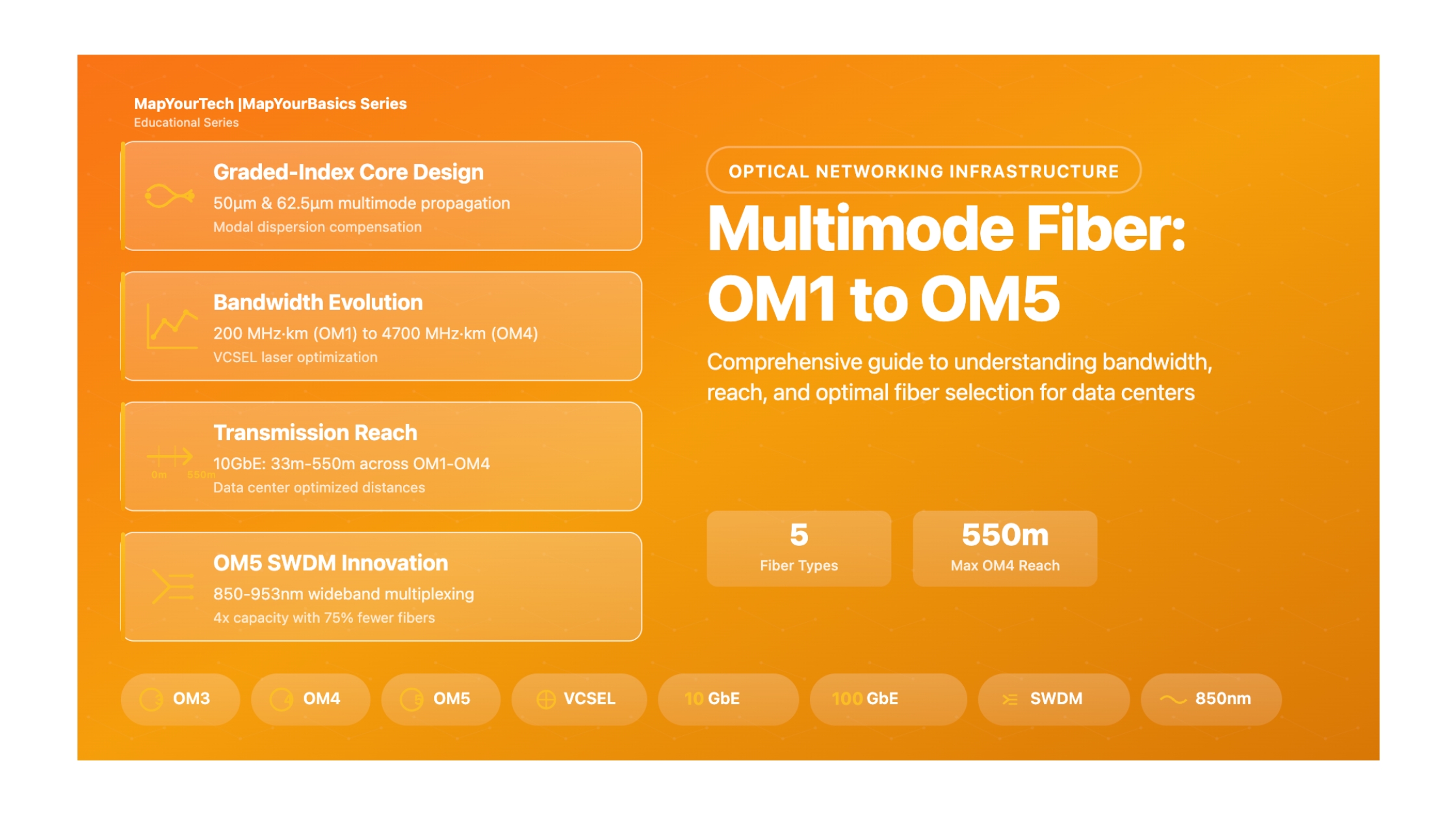
Multimode Fiber: OM1, OM2, OM3, OM4, OM5
1. Introduction
Multimode optical fiber represents one of the most critical infrastructure components in modern data centers, enterprise networks, and telecommunications systems. As data rates continue to escalate from 10 Gigabits per second (Gbps) to 400 Gbps and beyond, understanding the capabilities, limitations, and optimal applications of different multimode fiber types becomes increasingly important for network architects, engineers, and IT professionals.
This comprehensive guide explores the five primary categories of multimode fiber—designated as OM1, OM2, OM3, OM4, and OM5—each representing progressive advancements in optical fiber technology. These classifications, standardized by the Telecommunications Industry Association (TIA) and International Electrotechnical Commission (IEC), define specific performance characteristics that determine maximum transmission distances, supported data rates, and optimal deployment scenarios.
What is Multimode Fiber?
Multimode fiber is an optical fiber designed with a larger core diameter (typically 50 or 62.5 micrometers) that allows multiple light modes to propagate simultaneously through the fiber. This design contrasts with single-mode fiber, which has a much smaller core (8-10 micrometers) and supports only one propagation mode. The larger core of multimode fiber makes it more cost-effective for short-distance, high-bandwidth applications common in data centers and campus networks.
Why Multimode Fiber Matters
In the optical communications landscape, multimode fiber serves as the workhorse for short-reach, high-speed data transmission. Its importance stems from several key advantages:
Cost Efficiency: Multimode fiber transceivers and associated optical components are significantly less expensive than their single-mode counterparts. The larger core diameter relaxes alignment tolerances during connector mating, reducing installation complexity and cost.
Installation Simplicity: The more forgiving tolerances of multimode fiber make it easier to terminate, test, and troubleshoot. This translates to faster deployment times and reduced labor costs during network buildouts.
Adequate Performance for Short Distances: For applications within buildings, between adjacent buildings, or within data center environments (typically under 500-600 meters), multimode fiber provides sufficient bandwidth and reach while maintaining cost advantages.
Real-World Relevance and Applications
Multimode fiber finds extensive deployment across numerous applications and industries. Data centers represent the largest consumer of multimode fiber, where it connects switches, routers, and servers in high-density environments. Enterprise campus networks utilize multimode fiber for building-to-building connectivity and vertical riser applications. Storage area networks (SANs) leverage multimode fiber for high-speed, low-latency connections between storage systems and servers.
Financial institutions deploy multimode fiber in trading floors where ultra-low latency is critical. Healthcare facilities use it for medical imaging systems that require high-bandwidth, real-time data transfer. Educational institutions implement multimode fiber for campus-wide network backbones supporting thousands of concurrent users.
Industry Applications
The telecommunications industry increasingly adopts multimode fiber for 5G fronthaul and midhaul applications where fiber-to-the-antenna (FTTA) deployments require cost-effective solutions for short distances. Cloud service providers deploy massive quantities of multimode fiber in hyperscale data centers, where it enables high-speed interconnections between servers, top-of-rack switches, and spine switches.
Manufacturing facilities implement multimode fiber for industrial automation and control systems, benefiting from its immunity to electromagnetic interference. Broadcasting and media production companies rely on multimode fiber for real-time video transmission and studio interconnections.
2. Historical Context & Evolution
The evolution of multimode fiber technology spans more than four decades, reflecting the telecommunications industry's continuous pursuit of higher bandwidth, longer reach, and improved cost-efficiency. Understanding this historical progression provides valuable context for appreciating the capabilities and limitations of each fiber generation.
Early Development: The OM1 Era (1980s)
The first generation of standardized multimode fiber, designated OM1, emerged during the early 1980s as network infrastructure migrated from copper-based systems to optical fiber. OM1 fiber featured a relatively large core diameter of 62.5 micrometers, which facilitated easier connector alignment and termination with the technology available at that time. The fiber was optimized for operation with Light Emitting Diode (LED) sources, which were the predominant optical transmitters of that era.
OM1 fiber provided a modal bandwidth of 200 MHz·km at 850 nm wavelength, sufficient for the data rates and distances required by early local area networks (LANs) and telecommunications systems. These networks typically operated at speeds of 10 Mbps to 100 Mbps, well within OM1's capabilities. The orange jacket color became the industry standard for OM1 identification, a convention that persists today.
The Shift to 50µm Core: OM2 Introduction (Late 1990s)
As data rates increased toward 1 Gigabit Ethernet and beyond, the limitations of 62.5µm core fiber became apparent. The telecommunications industry responded by developing OM2 fiber, which featured a smaller 50µm core diameter. This reduction in core size decreased the number of propagating modes, thereby reducing modal dispersion and increasing bandwidth capability to 500 MHz·km at 850 nm.
VCSEL Revolution: OM3 Laser-Optimized Fiber (Early 2000s)
The introduction of Vertical Cavity Surface Emitting Laser (VCSEL) technology revolutionized multimode fiber applications. Unlike LEDs, which overfill the fiber core and excite all available modes, VCSELs launch light into a restricted mode field in the center of the core. This selective mode launch significantly reduces modal dispersion effects, enabling much higher bandwidth performance.
OM3 fiber, standardized in 2002, was specifically optimized for VCSEL operation at 850 nm. With an effective modal bandwidth of 2000 MHz·km, OM3 fiber supported 10 Gigabit Ethernet over distances up to 300 meters—a three-fold improvement over OM2. The adoption of aqua-colored jacketing distinguished OM3 from earlier fiber types, simplifying identification in mixed-fiber installations.
Extended Reach: OM4 Development (2008)
As 10 Gigabit Ethernet became mainstream and plans for 40/100 Gigabit Ethernet emerged, network operators required longer reach capabilities to accommodate larger data center designs. OM4 fiber, standardized in 2008, addressed this need by further improving modal bandwidth to 4700 MHz·km at 850 nm.
This enhancement enabled 10 GbE transmission over 550 meters—nearly doubling OM3's reach—and supported emerging 40/100 GbE standards over distances up to 150 meters using parallel optics. Despite retaining the aqua jacket color (potentially creating identification challenges with OM3), OM4 quickly became the preferred choice for new data center installations due to its superior performance and comparable cost to OM3.
Wideband Innovation: OM5 and SWDM (2016-Present)
The most recent evolution in multimode fiber technology is OM5, officially known as Wideband Multimode Fiber (WBMMF). Standardized by TIA in 2016 and by IEC in 2017, OM5 represents a paradigm shift in multimode fiber design philosophy. Rather than simply increasing bandwidth at the traditional 850 nm wavelength, OM5 fiber supports Shortwave Wavelength Division Multiplexing (SWDM) across a broad spectral range from 850 nm to 953 nm.
OM5 fiber maintains the same 2000 MHz·km bandwidth as OM3 at 850 nm but adds specification for operation at 953 nm with a minimum of 2470 MHz·km bandwidth. This wideband capability enables SWDM transmission, where four different wavelengths carry independent data streams over a single fiber pair. This approach effectively quadruples fiber capacity, enabling 100 Gigabit Ethernet over a single fiber pair rather than requiring four parallel fibers.
3. Core Concepts & Fundamentals
Understanding multimode fiber fundamentals requires grasping several interconnected concepts spanning optical physics, materials science, and telecommunications engineering. This section establishes the theoretical foundation necessary for comprehending multimode fiber behavior, performance characteristics, and practical limitations.
Light Propagation in Optical Fiber
Optical fiber operates on the principle of total internal reflection, a phenomenon that occurs when light traveling through a high-refractive-index medium (the fiber core) encounters the boundary with a lower-refractive-index medium (the fiber cladding) at an angle greater than the critical angle. Under these conditions, the light reflects back into the core rather than refracting into the cladding, enabling long-distance transmission with minimal loss.
In multimode fiber, the core diameter (50µm or 62.5µm) is significantly larger than the wavelength of light (typically 850nm or 1300nm). This dimensional relationship permits multiple distinct light paths, or modes, to propagate simultaneously through the fiber. Each mode represents a different angle of propagation relative to the fiber axis, with lower-order modes traveling more directly along the axis and higher-order modes reflecting more frequently off the core-cladding boundary.
Modal Behavior and Modal Dispersion
Modal dispersion represents the fundamental bandwidth-limiting factor in multimode fiber systems. Because different modes travel different path lengths through the fiber—with higher-order modes reflecting more frequently and thus traveling further—they arrive at the fiber's output at different times. This temporal spreading of the optical pulse degrades signal quality and limits the maximum achievable data rate.
In step-index multimode fiber (where the core has uniform refractive index), modal dispersion is severe, limiting bandwidth to approximately 20-50 MHz·km. Graded-index multimode fiber addresses this problem by implementing a core with a radially decreasing refractive index profile. The refractive index is highest at the fiber axis and gradually decreases toward the core-cladding boundary.
Bandwidth and Information Capacity
The bandwidth of multimode fiber is typically specified as a bandwidth-distance product, expressed in MHz·km or GHz·km. This specification indicates that as distance increases, available bandwidth decreases proportionally. For example, OM3 fiber with 2000 MHz·km bandwidth supports 2000 MHz over 1 km, 1000 MHz over 2 km, or 200 MHz over 10 km.
The relationship between fiber bandwidth and achievable data rate depends on the modulation format and encoding scheme employed. Non-Return-to-Zero (NRZ) modulation, commonly used in Ethernet applications, requires bandwidth approximately equal to half the data rate. Thus, 10 Gigabit Ethernet (requiring ~5 GHz bandwidth) can be transmitted over 400 meters of OM3 fiber (2000 MHz·km ÷ 0.4 km = 5000 MHz).
Attenuation and Loss Mechanisms
Attenuation—the reduction in optical power as light propagates through fiber—occurs through several mechanisms. Absorption losses arise from impurities in the glass, primarily hydroxyl (OH⁻) ions and transition metal ions. Scattering losses result from microscopic variations in glass density and composition, with Rayleigh scattering being the dominant contributor.
Modern multimode fiber exhibits attenuation of approximately 2.5-3.5 dB/km at 850 nm and 0.6-1.0 dB/km at 1300 nm. While these values are higher than single-mode fiber attenuation, they remain acceptably low for typical multimode applications spanning hundreds of meters. Additional losses occur at connectors (typically 0.3-0.75 dB per mated pair) and splices (0.1-0.3 dB).
4. Types, Variations & Classifications
Multimode fiber encompasses five primary classifications (OM1 through OM5), each with distinct specifications, performance characteristics, and optimal applications.
| Specification | OM1 | OM2 | OM3 | OM4 | OM5 |
|---|---|---|---|---|---|
| Core Diameter | 62.5 µm | 50 µm | 50 µm | 50 µm | 50 µm |
| Jacket Color | Orange | Orange | Aqua | Aqua | Lime Green |
| Bandwidth @ 850nm | 200 MHz·km | 500 MHz·km | 2000 MHz·km | 4700 MHz·km | 4700 MHz·km |
| Bandwidth @ 953nm | N/A | N/A | N/A | N/A | 2470 MHz·km |
| 1GbE Reach | 275 m | 550 m | 1000 m | 1000 m | 1000 m |
| 10GBASE-SR | 33 m | 82 m | 300 m | 550 m | 550 m |
| 25GBASE-SR | N/A | N/A | 70 m | 100 m | 100 m |
| 40GBASE-SR4 | N/A | N/A | 100 m | 150 m | 150 m |
| 100GBASE-SR4 | N/A | N/A | 100 m | 150 m | 150 m |
| 100G-SWDM4 | N/A | N/A | N/A | N/A | 150 m |
| Attenuation @ 850nm | ≤3.5 dB/km | ≤3.0 dB/km | ≤3.0 dB/km | ≤3.0 dB/km | ≤3.0 dB/km |
| Primary Use Case | Legacy | 1 GbE | 10 GbE | 10/25/100 GbE | 100/400 GbE SWDM |
| Cost Factor | 0.8x | 0.9x | 1.0x | 1.1-1.15x | 1.2-1.3x |
OM1 - Legacy 62.5µm Multimode Fiber
OM1 represents the first generation of standardized multimode fiber, developed for LED-based transmission systems in the 1980s. The 62.5µm core diameter facilitates easier coupling with LED sources and relaxes connector alignment tolerances. However, the larger core supports more propagating modes, resulting in higher modal dispersion and limited bandwidth compared to later fiber types.
OM2 - Standard 50µm Multimode Fiber
OM2 fiber introduced the 50µm core size that became the standard for subsequent multimode fiber generations. The smaller core reduces the number of propagating modes, decreasing modal dispersion and increasing bandwidth to 500 MHz·km at 850nm. OM2 was designed as network speeds increased toward Gigabit Ethernet and initially towards 10 Gigabit Ethernet.
OM3 - Laser-Optimized 50µm Fiber
OM3 fiber marked a revolutionary advancement in multimode technology by optimizing the refractive index profile specifically for VCSEL laser sources. The precisely controlled graded-index profile minimizes differential mode delay across the fiber core, achieving 2000 MHz·km bandwidth at 850nm—a four-fold improvement over OM2. The aqua jacket color provides clear visual distinction from earlier fiber types.
OM4 - Enhanced Laser-Optimized Fiber
OM4 fiber extended the laser-optimization concept of OM3 to achieve even tighter control of the refractive index profile and lower differential mode delay. With 4700 MHz·km bandwidth at 850nm, OM4 provides more than double the bandwidth-distance product of OM3. This enhancement enables longer-reach applications critical for large-scale data centers and campus networks.
OM5 - Wideband Multimode Fiber
OM5 fiber represents a paradigm shift in multimode technology by supporting Shortwave Wavelength Division Multiplexing (SWDM) across an extended wavelength range from 850nm to 953nm. Unlike previous fiber types optimized solely for 850nm operation, OM5 maintains high bandwidth performance across four wavelengths (typically 850, 880, 910, and 940nm), enabling wavelength multiplexing on multimode fiber for the first time.
5. Interactive Simulators
Simulator 1: Link Performance Calculator
Simulator 2: Fiber Type Comparison Tool
| Fiber | Max Reach | Status |
|---|
Simulator 3: Bandwidth-Distance Analysis
Simulator 4: Advanced Link Budget Calculator
6. Practical Applications & Case Studies
Real-world deployment of multimode fiber systems requires careful consideration of application requirements, environmental conditions, and future scalability needs.
Case Study 1: Enterprise Data Center 10 GbE Upgrade
Challenge
A Fortune 500 financial services company needed to upgrade its primary data center from 1 Gigabit Ethernet to 10 Gigabit Ethernet to support increasing transaction volumes and real-time analytics workloads. The existing infrastructure consisted of OM2 multimode fiber installed in 2002, with maximum link distances of 220 meters.
Solution: After comprehensive testing, the team selected a hybrid approach. Short links under 80 meters reused existing OM2 fiber with 10GBASE-SR optics, while longer links received new OM4 fiber installation.
Results: The upgrade completed in 4 months with 99.9% uptime maintained. Total project cost came in 35% below the initial estimate for complete fiber replacement. The OM4 infrastructure now supports 10 GbE with substantial margin for future 25 GbE upgrades.
Case Study 2: Hyperscale Cloud Provider 100 GbE Deployment
Challenge
A major cloud service provider needed to deploy 100 Gigabit Ethernet connectivity in a new 15,000 square meter data center facility supporting high-density compute and storage infrastructure.
Solution: The infrastructure team selected OM5 fiber with SWDM technology (100GBASE-SWDM4 requiring 2 fibers per link) versus OM4 with parallel optics (requiring 8 fibers per link). Despite higher per-meter fiber costs for OM5, the 75% reduction in fiber count provided overall cost savings.
Results: The OM5 deployment reduced fiber count by 60% compared to the original OM4 parallel optics design. Installation time decreased by 25% due to lower fiber counts and pre-terminated assemblies. The infrastructure supports both 100GBASE-SWDM4 and 100GBASE-SR4 transceivers.
Deployment Best Practices
Design Phase: Conduct thorough site surveys, design with 25-50% capacity margin for future growth, standardize on single fiber type per facility, include adequate spare fibers (20-30%), plan for accessibility of all splice points.
Installation Phase: Maintain minimum bend radius (30mm for multimode fiber), avoid excessive pulling tension (max 600 newtons for 12-fiber cable), protect fiber ends with dust caps, test every fiber link before accepting installation, document as-built conditions.
Troubleshooting Guide
| Symptom | Possible Causes | Resolution |
|---|---|---|
| Link will not establish | Wrong fiber type, damaged connector, incorrect polarity | Visual inspection, verify fiber specs, correct polarity |
| Intermittent errors | Dirty connectors, loose connections | Clean/replace connectors, reseat connections |
| High bit error rate | Modal dispersion, excessive loss | Upgrade fiber type, reduce distance |
| Reduced performance | Fiber bandwidth limitation | Use higher-grade fiber, consider single-mode |
7. Key Takeaways Summary
Fiber Selection: OM4 represents optimal balance of performance and cost for most modern data center applications.
Bandwidth Fundamentals: Modal dispersion is the primary bandwidth-limiting factor. Higher-grade fibers provide proportionally better specifications.
Distance Limitations: OM4 extends 10 GbE to 550m and 100 GbE to 150m—critical for data center topology design.
VCSEL Optimization: Modern multimode fiber is specifically optimized for VCSEL laser sources.
Backward Compatibility: All 50µm fibers use identical connectors, enabling mixed installations.
Cost-Performance: OM4 costs only 10-15% more than OM3 but provides nearly double the bandwidth-distance product.
Link Budget: Successful optical link design requires accounting for fiber attenuation, connector losses, and adequate system margin (2-3 dB).
Standards Compliance: IEEE 802.3 and TIA/IEC standards define precise specifications. Following standardized distance specifications ensures reliable interoperability.
Installation Quality: Proper installation practices including bend radius management and thorough testing are essential.
Future-Proofing: Installing higher-grade fiber than immediate requirements provides significant flexibility for future upgrades.
Note: This guide is based on industry standards, best practices, and real-world implementation experiences. Specific implementations may vary based on equipment specifications, network topology, and regulatory requirements. Always consult with qualified network engineers and follow manufacturer documentation for actual deployments.
Developed by MapYourTech Team
For educational purposes in optical networking and telecommunications systems
Unlock Premium Content
Join over 400K+ optical network professionals worldwide. Access premium courses, advanced engineering tools, and exclusive industry insights.
Already have an account? Log in here