

LR4 vs LR1: Complete Guide to 100G Optical Transceivers
Understanding the Evolution from Multi-Wavelength to Single-Lambda Technology in Long-Reach Optical Communications
Introduction
In the rapidly evolving landscape of optical networking, the transition from 100GBASE-LR4 to 100GBASE-LR1 represents a significant technological milestone that is reshaping data center interconnections and telecommunications infrastructure worldwide. This comprehensive guide explores the fundamental differences, technical innovations, and practical implications of these two critical optical transceiver technologies.
What Are LR4 and LR1?
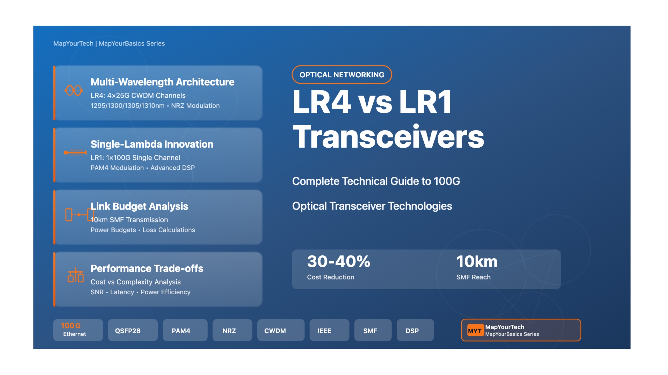
100GBASE-LR4 (commonly known as LR4) is a mature optical transceiver standard introduced in 2010 as part of IEEE 802.3ba. It achieves 100 Gigabit per second (Gbps) transmission by utilizing four separate wavelengths, each carrying 25 Gbps using Non-Return-to-Zero (NRZ) modulation. These four wavelengths are combined through Coarse Wavelength Division Multiplexing (CWDM) technology to create a single 100G data stream over distances up to 10 kilometers on single-mode fiber.
100GBASE-LR1 (commonly known as LR1 or single-lambda LR) is a next-generation optical transceiver technology that achieves the same 100 Gbps transmission rate using a single wavelength at approximately 1310 nanometers. By employing advanced Pulse Amplitude Modulation with 4 levels (PAM4), LR1 consolidates four 25G electrical lanes into one 100G optical channel, eliminating the need for wavelength multiplexing and demultiplexing components.
Why This Comparison Matters
The choice between LR4 and LR1 transceivers has far-reaching implications for network architecture, operational expenses, power consumption, and future scalability. As data centers continue their inexorable march toward higher bandwidth requirements—driven by cloud computing, artificial intelligence, machine learning, and video streaming services—understanding these technologies becomes crucial for network engineers, data center operators, and telecommunications professionals.
Real-World Relevance and Applications
Both LR4 and LR1 transceivers serve critical roles in modern network infrastructure, particularly in scenarios requiring long-reach connectivity:
- Data Center Interconnection (DCI): Connecting geographically distributed data centers within metropolitan areas, typically spanning 2-10 kilometers
- Campus Networks: Linking buildings across large enterprise campuses or university installations
- Telecommunications Backbone: Providing high-capacity trunk connections in service provider networks
- Cloud Infrastructure: Enabling hyperscale cloud providers to build high-bandwidth, cost-effective interconnection fabrics
- 5G Fronthaul/Backhaul: Supporting the massive bandwidth requirements of next-generation mobile networks
Key Concepts Preview
Before diving into the detailed technical analysis, it's essential to understand several foundational concepts that underpin the LR4 vs LR1 discussion:
Fundamental Technical Distinctions
Modulation Schemes: LR4 uses NRZ (2 levels per symbol) while LR1 employs PAM4 (4 levels per symbol), representing fundamentally different approaches to encoding digital data onto optical carriers.
Wavelength Architecture: LR4 distributes the 100G signal across four CWDM wavelengths (approximately 1295, 1300, 1305, and 1310 nm), whereas LR1 concentrates the entire signal onto a single wavelength around 1310 nm.
Component Complexity: LR4 requires four discrete laser transmitters, four photodetectors, and integrated CWDM multiplexers/demultiplexers. LR1 simplifies this to a single laser, single photodetector, and eliminates wavelength-selective components.
Signal Processing: LR1 relies heavily on advanced Digital Signal Processing (DSP) to manage the increased complexity of PAM4 modulation, whereas LR4 uses simpler signal processing with parallel NRZ channels.
The emergence of LR1 technology represents more than just an incremental improvement—it signals a paradigm shift in how the industry approaches optical transceiver design. This shift mirrors broader trends in photonics integration, where increased electronic sophistication (DSP) enables simpler optical architectures, ultimately reducing costs and improving scalability.
As we progress through this guide, you'll gain comprehensive knowledge spanning from theoretical fundamentals to practical implementation considerations, empowering you to make informed decisions about optical transceiver selection and network architecture design in your own projects and deployments.
Historical Context & Evolution
The Dawn of 100G Optical Networking (2010-2012)
The journey toward 100 Gigabit Ethernet began in earnest in the mid-2000s when the IEEE formed the Higher Speed Study Group to address the growing bandwidth demands of data centers and telecommunications networks. In June 2010, the IEEE ratified the 802.3ba standard, marking a watershed moment in optical networking history by officially defining multiple 100G Ethernet specifications, including the seminal 100GBASE-LR4.
The Genesis of 100GBASE-LR4
The LR4 specification emerged from practical engineering constraints of the era. Switch and router ASICs in 2010 primarily operated with 10G SERDES (Serializer/Deserializer) interfaces. To bridge the gap to 100G transmission, engineers developed a parallel approach: combine four 25G NRZ channels using CWDM technology. This solution leveraged mature 25G laser technology while achieving the desired 100G aggregate rate.
The initial deployments of 100GBASE-LR4 utilized the CFP (C Form-Factor Pluggable) transceiver format, a relatively large module measuring approximately 144.8 x 82 x 13.6 millimeters. Despite its considerable size—comparable to an external phone power bank—CFP enabled early adopters, primarily large service providers and hyperscale data centers, to deploy 100G uplinks in their networks beginning in 2011-2012.
Form Factor Evolution: From CFP to QSFP28 (2012-2016)
As silicon photonics matured and integration techniques improved, the industry embarked on an aggressive miniaturization campaign. The progression followed a clear trajectory:
- CFP (2010-2012): First-generation 100G form factor, dimensions ~145mm x 82mm x 14mm, power consumption up to 32W
- CFP2 (2013-2014): Reduced size to ~107mm x 42mm x 12mm, improved power efficiency to ~12W
- CFP4 (2014-2015): Further miniaturization to ~86mm x 21mm x 9mm, power consumption ~6W
- QSFP28 (2014-present): Current industry standard, compact ~72mm x 18mm x 9mm, power consumption typically 3.5-5W
The QSFP28 (Quad Small Form-Factor Pluggable 28) form factor represented a crucial milestone. Its compact size enabled dramatically higher port densities—network switches could now support 32 or even 64 100G ports in a standard 1U chassis, compared to just 4-8 CFP ports. This density improvement proved essential for building cost-effective 100G spine-leaf architectures in modern data centers.
The Emergence of Single-Lambda Concepts (2016-2020)
While LR4 technology matured and became ubiquitous, forward-thinking engineers recognized inherent limitations in the four-wavelength architecture. Each LR4 transceiver required four discrete laser diodes, four photodetectors, and complex CWDM multiplexer/demultiplexer optical components. These elements contributed significantly to manufacturing costs, power consumption, and potential failure points.
Around 2016-2017, industry consortia began exploring single-lambda alternatives. The 100G Lambda MSA (Multi-Source Agreement), formed by leading optical component manufacturers and network equipment vendors, established specifications for single-wavelength 100G transmission. These efforts ran parallel to similar initiatives for 400G (where single-lambda approaches also showed promise for certain reach applications).
Standardization and Commercial Availability (2020-Present)
The transition from LR4 to LR1 accelerated dramatically around 2020-2021 as several factors converged:
- PAM4 DSP Maturity: Digital signal processors capable of sophisticated equalization, chromatic dispersion compensation, and forward error correction became cost-effective and power-efficient
- Economic Pressures: The relentless demand for 100G ports in hyperscale data centers created intense pressure to reduce per-port costs
- 400G Migration Path: LR1 technology provided an elegant solution for connecting legacy 100G infrastructure to newer 400G equipment using breakout configurations
- Manufacturing Scale: Volume production of PAM4 transceivers for 400G applications created economies of scale that benefited 100G LR1 development
| Year | Milestone | Impact |
|---|---|---|
| 2010 | IEEE 802.3ba ratification | Official 100GBASE-LR4 standard established |
| 2011-2012 | First CFP LR4 deployments | Early adopter 100G networks go live |
| 2014 | QSFP28 form factor introduction | Enabled high-density 100G switching |
| 2016-2017 | 100G Lambda MSA formation | Industry collaboration on single-lambda specs |
| 2019-2020 | First LR1 commercial products | Single-lambda becomes viable alternative |
| 2021-2023 | Widespread LR1 adoption | Cost reduction drives market transition |
| 2024-Present | LR1 becomes standard for new deployments | LR4 primarily legacy/replacement market |
Current State and Market Dynamics
As of 2024-2025, the optical transceiver market has reached an inflection point. Major internet exchange points and data center operators are actively standardizing on LR1 for new 100G deployments. For example, DE-CIX (Deutscher Commercial Internet Exchange), one of the world's largest internet exchange operators, announced in 2022 that LR1 would become their standard 100G technology for new port provisioning.
Industry analysts estimate that LR1 transceivers typically cost 30-40% less than equivalent LR4 modules while consuming approximately 15-20% less power. These economic advantages, combined with simplified inventory management (fewer SKUs needed) and improved reliability (fewer optical components), have created a compelling value proposition for network operators.
Pioneer Contributions and Key Players
The evolution from LR4 to LR1 represents contributions from numerous companies and research institutions across the optical networking ecosystem:
- Optical Component Manufacturers: Companies specializing in laser diodes, photodetectors, and integrated photonic circuits developed the high-performance single-wavelength components required for LR1
- DSP Silicon Vendors: Semiconductor companies created increasingly sophisticated signal processing chips capable of handling PAM4's higher complexity
- Transceiver Module Manufacturers: Integrators who assemble components into complete QSFP28 modules drove manufacturing optimization and cost reduction
- Network Equipment Vendors: Switch and router manufacturers collaborated on specifications and provided crucial early deployments
- Hyperscale Operators: Large cloud and content providers drove demand and provided deployment feedback that shaped product evolution
Future Outlook: Beyond 100G
The single-lambda paradigm pioneered by LR1 is now extending to higher speeds. Similar technologies are emerging for:
- 200G Single-Lambda: Using PAM4 on a single 200G channel for medium-reach applications
- 400G DR1/FR1: Single-wavelength 400G solutions for data center and campus networks
- 800G and Beyond: Research into higher-order modulation formats (PAM8, probabilistic constellation shaping) to push single-wavelength capacity even higher
The technological trajectory suggests that single-lambda approaches will continue gaining market share across multiple speed grades, driven by their inherent cost and complexity advantages. However, multi-wavelength technologies like LR4 will remain relevant for specific applications requiring particular characteristics (such as superior signal-to-noise ratios in challenging environments).
Looking forward to 2025 and beyond, the optical transceiver industry stands at the threshold of another transition—from 100G to 400G as the dominant data center interconnect speed. The lessons learned from the LR4-to-LR1 evolution are directly informing the design of next-generation technologies, creating a continuous cycle of innovation that balances performance, cost, power efficiency, and manufacturability.
Core Concepts & Fundamentals
Fundamental Principles of Optical Transmission
Before examining the specific differences between LR4 and LR1, we must establish a foundation in the fundamental principles governing optical fiber communication. At its core, optical transmission involves converting electrical signals into optical signals (light), propagating that light through an optical fiber, and converting it back to electrical signals at the receiving end.
The Basic Optical Link
Every optical link consists of three essential elements:
- Transmitter: Converts electrical signals to optical signals using a laser diode or LED
- Optical Fiber: Guides light from transmitter to receiver with minimal loss and distortion
- Receiver: Converts optical signals back to electrical signals using a photodetector
Key Terminology and Definitions
Understanding the technical discussion requires familiarity with specialized terminology used throughout optical networking:
| Term | Definition | Significance |
|---|---|---|
| Wavelength (λ) | The physical distance between successive peaks of a light wave, measured in nanometers (nm) | Determines optical carrier frequency and compatibility with fiber transmission windows |
| Modulation | The process of varying optical signal properties to encode information | Different modulation schemes trade off between data rate, reach, and complexity |
| NRZ (Non-Return-to-Zero) | Binary modulation using two signal levels (0 and 1) | Simple, robust, but limited to one bit per symbol |
| PAM4 (Pulse Amplitude Modulation-4) | Modulation using four signal levels (00, 01, 10, 11) | Encodes two bits per symbol, doubling spectral efficiency |
| Symbol Rate (Baud) | Number of symbols transmitted per second, measured in GBd (gigabaud) | Determines required electrical and optical bandwidth |
| CWDM (Coarse WDM) | Wavelength division multiplexing with ~20nm channel spacing | Enables multiple signals on one fiber using different wavelengths |
| OMA (Optical Modulation Amplitude) | The difference between average optical power of high and low signal levels | Key parameter for link budget calculations |
| TDECQ (Transmitter Dispersion Eye Closure Quaternary) | PAM4 signal quality metric including chromatic dispersion effects | Critical specification for PAM4 transmitter performance |
How 100GBASE-LR4 Works: Step-by-Step Process
The LR4 transceiver operates through a carefully orchestrated sequence of signal transformations:
Transmit Path (Electrical to Optical)
- Lane Distribution: The host ASIC presents 100G data as four parallel 25G electrical lanes (CAUI-4 interface). Each lane carries 25.78125 Gbps using NRZ encoding.
- Laser Modulation: Each of the four electrical lanes drives a separate Distributed Feedback (DFB) laser. The four lasers operate at distinct CWDM wavelengths:
- Lane 0: ~1295.56 nm
- Lane 1: ~1300.05 nm
- Lane 2: ~1304.58 nm
- Lane 3: ~1309.14 nm
- Wavelength Multiplexing: The four separate optical signals pass through an integrated CWDM multiplexer (MUX), a passive optical component using thin-film filters that combines all four wavelengths onto a single optical path.
- Fiber Launch: The multiplexed signal exits through a duplex LC connector onto a single strand of single-mode fiber (one fiber for transmit, one for receive).
Receive Path (Optical to Electrical)
- Signal Reception: The multiplexed 100G optical signal arrives at the receiver's LC connector.
- Wavelength Demultiplexing: A CWDM demultiplexer (DEMUX) separates the combined signal back into four individual wavelength channels using wavelength-selective filters.
- Photo-Detection: Each wavelength illuminates a dedicated PIN or APD photodetector, which converts optical power variations into electrical current.
- Signal Processing: Transimpedance amplifiers (TIAs) convert photodetector currents into voltage signals, which are then processed by Clock and Data Recovery (CDR) circuits to regenerate clean 25G electrical data streams.
- Lane Aggregation: The four recovered 25G electrical lanes are presented to the host ASIC through the CAUI-4 interface, reconstituting the original 100G data stream.
LR4 Key Characteristic: Parallel Simplicity
The beauty of LR4 architecture lies in its parallel nature. Each 25G channel operates independently with relatively simple NRZ modulation. The electrical bandwidth requirements per lane remain modest (~13-14 GHz), allowing use of mature, cost-effective laser and detector technologies. Complexity resides primarily in the passive CWDM multiplexing optics rather than advanced signal processing.
How 100GBASE-LR1 Works: Step-by-Step Process
The LR1 transceiver employs a fundamentally different architecture optimized around single-wavelength transmission:
Transmit Path (Electrical to Optical)
- Lane Reception: Like LR4, the host ASIC provides four 25G electrical lanes totaling 100G capacity.
- Digital Signal Processing: A sophisticated DSP chip performs several critical functions:
- Combines the four 25G NRZ lanes into a single 100G serial data stream
- Applies pre-emphasis and feed-forward equalization to compensate for transmitter impairments
- Encodes the 100G stream using PAM4 modulation, reducing the symbol rate from 100 GBd to 53.125 GBd (since each PAM4 symbol carries 2 bits)
- Implements pre-distortion algorithms to linearize the laser's electrical-to-optical transfer function
- Laser Modulation: A single high-performance DFB or EML (Electro-absorption Modulated Laser) at ~1310 nm converts the 53.125 GBd PAM4 electrical signal to optical form. The laser must exhibit excellent linearity, low relative intensity noise (RIN), and tight wavelength control.
- Fiber Launch: The single-wavelength optical signal launches directly onto the fiber through a duplex LC connector—no wavelength multiplexing required.
Receive Path (Optical to Electrical)
- Signal Reception: The 100G PAM4 signal arrives at the receiver.
- Photo-Detection: A single wideband photodetector converts the optical PAM4 signal to an electrical PAM4 signal. This photodetector must have sufficient bandwidth (~40+ GHz) to capture the 53.125 GBd signal.
- Advanced Signal Processing: The receiver DSP performs extensive digital signal processing:
- Analog-to-Digital Conversion (ADC) samples the PAM4 waveform at high speed
- Adaptive equalization compensates for channel impairments (chromatic dispersion, fiber bandwidth limitations, inter-symbol interference)
- Clock recovery extracts accurate timing information from the received signal
- Decision feedback equalization (DFE) reduces residual inter-symbol interference
- PAM4 symbol decisions determine which of the four levels each symbol represents
- Forward Error Correction (FEC) detects and corrects bit errors
- De-serialization converts the 100G stream back to four 25G NRZ electrical lanes
- Lane Distribution: The recovered four 25G lanes are presented to the host ASIC.
Conceptual Models: Understanding the Fundamental Difference
To solidify understanding, consider these conceptual models:
The Highway Analogy
- LR4: Imagine a four-lane highway where each lane carries cars traveling at 25 mph. Total throughput is 100 cars per hour (4 lanes × 25 mph). Each lane is simple and independent.
- LR1: Imagine a single-lane highway where cars travel at 100 mph. However, to safely maintain this higher speed, sophisticated traffic management systems (DSP) are required—adaptive cruise control, lane-keeping assistance, collision avoidance—representing the electronic complexity needed to handle the higher data rate on a single channel.
The Information Encoding Analogy
- LR4 (NRZ): Like Morse code with just dots and dashes (two symbols). Simple to encode and decode, but requires more time to transmit a given amount of information.
- LR1 (PAM4): Like a language with four distinct phonemes per time slot instead of two. Conveys information more efficiently but requires more sophisticated processing to distinguish between the four levels, especially in the presence of noise.
Component Breakdown and Roles
| Component | LR4 Implementation | LR1 Implementation | Functional Role |
|---|---|---|---|
| Laser Source | Four DFB lasers (1295, 1300, 1305, 1310 nm) | Single DFB or EML laser (~1310 nm) | Converts electrical signals to optical signals |
| Photodetector | Four PIN photodiodes | Single high-bandwidth PIN or APD | Converts optical signals to electrical signals |
| Multiplexer/Demultiplexer | CWDM MUX/DEMUX using thin-film filters | Not required | Combines/separates wavelengths |
| DSP Chip | Minimal (primarily CDR functions) | Advanced (PAM4 encoding/decoding, equalization, FEC) | Signal conditioning and error correction |
| Laser Driver | Four analog drivers for 25G NRZ | One high-speed driver for 53.125 GBd PAM4 | Amplifies electrical signals to drive laser |
| TIA (Transimpedance Amplifier) | Four TIAs for 25G channels | One wideband TIA for 53.125 GBd | Converts photodetector current to voltage |
Mathematical Foundations
Several fundamental mathematical relationships govern optical transmission and differentiate LR4 from LR1:
For NRZ (LR4):
Bit Rate = Symbol Rate × 1 bit/symbol
100 Gbps = (4 lanes × 25.78125 Gbps/lane) = 4 × 25.78125 GBd × 1
For PAM4 (LR1):
Bit Rate = Symbol Rate × 2 bits/symbol
100 Gbps = 53.125 GBd × 2 bits/symbol
Approximate electrical bandwidth ≈ 0.75 × Symbol Rate
LR4 per lane: BW ≈ 0.75 × 25.78125 GBd ≈ 19.3 GHz
LR1 single channel: BW ≈ 0.75 × 53.125 GBd ≈ 39.8 GHz
This explains why LR1 requires more sophisticated (higher bandwidth) optical and electrical components
Signal Quality Metrics
Different modulation formats require different approaches to characterizing signal quality:
LR4 Signal Quality: Eye Diagram and Extinction Ratio
Eye Diagram: For NRZ signals, the "eye" opening represents noise margin. A wider, taller eye indicates better signal quality.
Extinction Ratio (ER): The ratio between optical power in "1" state versus "0" state. Typical requirement: ER > 4.5 dB
Optical Modulation Amplitude (OMA): The difference in optical power between high and low states, directly related to receiver sensitivity.
LR1 Signal Quality: TDECQ
TDECQ (Transmitter Dispersion Eye Closure Quaternary): PAM4 signals have three eye openings (between four levels). TDECQ quantifies how much these eyes close due to transmitter impairments and chromatic dispersion.
SECQ (Stressed Eye Closure Quaternary): Measures receiver's ability to recover PAM4 signals with various impairments applied.
Lower TDECQ and SECQ values indicate better quality (typical specifications: TDECQ < 3.4 dB).
These fundamental concepts form the foundation for understanding the architectural, performance, and economic trade-offs between LR4 and LR1 technologies. As we progress to more detailed technical analysis in subsequent sections, these core principles will provide essential context for evaluating design choices and practical deployment considerations.
Technical Architecture & Components
System Architecture Overview
The architectural differences between LR4 and LR1 transceivers reflect fundamentally different design philosophies regarding optical versus electronic complexity. Understanding these architectures provides insight into performance characteristics, cost structures, and reliability considerations.
Transmitter Architecture
The LR4 transmitter represents a highly parallelized optical architecture with moderate electronic complexity:
- CAUI-4 Interface: Receives four 25.78125 Gbps electrical lanes from the host ASIC using differential signaling
- Laser Array: Four independently controlled Distributed Feedback (DFB) lasers, each emitting at a specific CWDM wavelength
- Laser Drivers: Four analog driver circuits that convert low-swing electrical signals to the higher current levels needed to modulate the lasers
- CWDM Multiplexer: Passive optical component using thin-film interference filters deposited on glass substrates, typically arranged in a cascaded configuration
- Optical Isolator: Prevents back-reflections from reaching the lasers, which could cause instability or damage
CWDM Wavelength Plan for LR4
The four wavelengths follow the CWDM grid defined in ITU-T G.694.2:
- Lane 0 (λ0): 1294.53 to 1296.59 nm (center ~1295.56 nm)
- Lane 1 (λ1): 1299.02 to 1301.09 nm (center ~1300.05 nm)
- Lane 2 (λ2): 1303.54 to 1305.63 nm (center ~1304.58 nm)
- Lane 3 (λ3): 1308.09 to 1310.19 nm (center ~1309.14 nm)
The ~5 nm spacing allows simple filter-based multiplexing without requiring tight wavelength control
Receiver Architecture
The LR4 receiver mirrors the transmitter's parallel structure:
- Optical Demultiplexer: Separates the four wavelengths using wavelength-selective filters (reverse of the transmitter multiplexer)
- Photodetector Array: Four PIN photodiodes, each optimized for its specific wavelength range
- Transimpedance Amplifiers (TIAs): Convert photodetector currents (typically μA to mA range) to voltage signals suitable for subsequent processing
- Limiting Amplifiers: Provide additional gain and convert analog signals to clean digital levels
- Clock and Data Recovery (CDR): Four independent CDR circuits extract timing and regenerate the 25G data streams
- CAUI-4 Interface: Delivers the recovered four 25G lanes to the host ASIC
Transmitter Architecture
The LR1 transmitter concentrates complexity in digital signal processing while simplifying the optical components:
- CAUI-4 Interface: Receives the same four 25G lanes as LR4
- Serializer/DSP: A sophisticated integrated circuit that:
- Combines (serializes) the four 25G NRZ streams into a single 100G stream
- Performs PAM4 encoding, converting 100 Gbps into 53.125 GBd PAM4
- Applies pre-emphasis (high-frequency boost) to compensate for bandwidth limitations
- Implements feed-forward equalization to pre-distort the signal
- May include partial forward error correction encoding
- Digital-to-Analog Converter (DAC): High-speed DAC generates the analog PAM4 waveform from digital samples, typically operating at 2-4 samples per symbol
- Laser Driver: High-bandwidth linear driver that can accurately reproduce the four PAM4 levels
- Single Laser: Either a DFB laser with external modulator or an Electro-absorption Modulated Laser (EML) operating at ~1310 nm
Receiver Architecture
The LR1 receiver employs even more sophisticated signal processing than the transmitter:
- Single Photodetector: High-bandwidth (40+ GHz) photodiode converts the optical PAM4 signal to electrical form
- Transimpedance Amplifier: Wideband TIA with carefully controlled frequency response
- Variable Gain Amplifier (VGA): Provides automatic gain control to optimize signal levels for the ADC
- Analog-to-Digital Converter (ADC): High-speed (typically 2-4 samples per symbol) ADC digitizes the PAM4 waveform
- Digital Signal Processor: Performs extensive processing:
- Timing recovery (determines symbol boundaries)
- Adaptive equalization (compensates for channel impairments)
- Decision feedback equalization (removes residual inter-symbol interference)
- Forward error correction decoding (corrects bit errors)
- PAM4 to NRZ conversion
- Deserialization back to four 25G lanes
- CAUI-4 Interface: Outputs the recovered four 25G lanes
Component Comparison and Trade-offs
| Architecture Aspect | LR4 Approach | LR1 Approach | Implications |
|---|---|---|---|
| Optical Complexity | High (4 lasers, CWDM optics) | Low (1 laser, no WDM) | LR1 eliminates expensive optical components |
| Electronic Complexity | Low (simple NRZ, basic CDR) | High (PAM4 DSP, equalization, FEC) | LR1 requires sophisticated signal processing ASICs |
| Component Bandwidth | Moderate (~20 GHz per lane) | High (~40 GHz single channel) | LR1 needs higher-speed optical and RF components |
| Power Consumption | ~3.5-5W typical | ~3.0-4.2W typical | LR1 slightly more efficient despite DSP |
| Manufacturing Complexity | Moderate (optical alignment critical) | Lower (fewer optical alignments) | LR1 potentially higher yield and lower cost |
| Failure Points | More (4 laser paths) | Fewer (1 laser path) | LR1 potentially more reliable |
Data Flow and Signal Transformations
Understanding how signals flow through these architectures clarifies the operational differences:
LR4 Signal Flow (Transmit)
Step 1: Electrical signals: 4 × 25.78125 Gbps NRZ (differential electrical)
Step 2: After laser modulation: 4 × 25.78125 Gbps NRZ (optical, different wavelengths)
Step 3: After CWDM MUX: 1 × 100 Gbps (4 wavelengths combined on single fiber)
Step 4: Propagation through 10 km fiber (signal degradation due to attenuation, dispersion)
Key characteristic: Primarily optical domain transformations
LR1 Signal Flow (Transmit)
Step 1: Electrical signals: 4 × 25.78125 Gbps NRZ (differential electrical)
Step 2: After serialization: 1 × 100 Gbps NRZ (serial electrical)
Step 3: After PAM4 encoding: 1 × 53.125 GBd PAM4 (serial electrical, 4 levels)
Step 4: After DAC and pre-equalization: Analog PAM4 waveform (pre-compensated)
Step 5: After laser modulation: 53.125 GBd PAM4 (optical, single wavelength ~1310 nm)
Step 6: Propagation through 10 km fiber (attenuation, dispersion, noise accumulation)
Key characteristic: Heavy digital signal processing before optical conversion
Implementation Layers and Protocol Stack
Both LR4 and LR1 transceivers implement the same high-level Ethernet protocols but differ in the physical layer implementation:
| Layer | Description | LR4 & LR1 Commonality |
|---|---|---|
| MAC (Media Access Control) | Ethernet frame handling, flow control | Identical - both implement 100G Ethernet MAC |
| RS (Reconciliation Sublayer) | Interface between MAC and PCS | Identical - standardized XLGMII or CAUI interface |
| PCS (Physical Coding Sublayer) | 64b/66b encoding, scrambling, alignment | Identical - same PCS regardless of PMD |
| FEC (Forward Error Correction) | Reed-Solomon error correction | LR4: Optional; LR1: Typically required for performance |
| PMA (Physical Medium Attachment) | Serializer/deserializer, lane distribution | Different: LR4 = 4×25G lanes; LR1 = 4×25G→100G serialization |
| PMD (Physical Medium Dependent) | Modulation, optical transmission/reception | Completely different: LR4 = 4λ NRZ; LR1 = 1λ PAM4 |
| MDI (Medium Dependent Interface) | Physical connector and fiber | Identical - duplex LC connector, SMF |
Protocols and Standards Compliance
Both transceiver types must comply with multiple overlapping standards:
- IEEE 802.3ba: Original 100G Ethernet specification (2010) - defines LR4
- 100G Lambda MSA: Industry consortium specification for single-lambda 100G including LR1
- QSFP28 MSA: Mechanical, electrical, and thermal specifications for the form factor
- ITU-T G.652: Single-mode fiber specification (both use SMF)
- ITU-T G.957/G.959.1: Optical interface parameters for SDH/SONET equipment (referenced for some specifications)
Mathematical Models & Formulas
Link Budget Calculations
The optical link budget is fundamental to understanding whether a specific transceiver can reliably operate over a given fiber link. The link budget accounts for all sources of optical power loss and gain between transmitter and receiver.
P_RX = P_TX - L_total + G_total
Where:
- P_RX = Received optical power (dBm)
- P_TX = Transmitted optical power (dBm)
- L_total = Total link losses (dB)
- G_total = Total link gains (dB) - typically 0 for passive links
Link Budget Margin = P_RX - Receiver_Sensitivity
Positive margin indicates the link will function reliably
Total Loss Calculation
Total link loss comprises multiple contributors:
L_total = L_fiber + L_connectors + L_splices + L_margin
L_fiber: Fiber attenuation = α × Distance
- α = Fiber attenuation coefficient (typically 0.25-0.35 dB/km for SMF at 1310 nm)
- Distance = Link length in kilometers
- Example: For 10 km link → L_fiber = 0.30 dB/km × 10 km = 3.0 dB
L_connectors: Connector insertion loss
- Typical LC connector: 0.3-0.5 dB per connector
- Example: Two connectors (TX and RX) → 0.4 dB × 2 = 0.8 dB
L_splices: Fusion splice loss
- Typical: 0.05-0.1 dB per splice
- Example: Two splices → 0.1 dB × 2 = 0.2 dB
L_margin: Safety margin for aging, temperature, etc.
- Typical: 1-3 dB
- Example: 2.0 dB margin
Practical Example: 10 km Link Budget
| Parameter | LR4 (per lane) | LR1 (single channel) | Units |
|---|---|---|---|
| Transmit Power (min) | -4.3 | -1.4 | dBm |
| Fiber Loss (10 km × 0.3 dB/km) | -3.0 | -3.0 | dB |
| Connector Loss (2 × 0.4 dB) | -0.8 | -0.8 | dB |
| Splice Loss (2 × 0.1 dB) | -0.2 | -0.2 | dB |
| System Margin | -2.0 | -2.0 | dB |
| Received Power | -10.3 | -7.4 | dBm |
| Receiver Sensitivity | -10.6 | -6.6 | dBm |
| Link Margin | +0.3 | -0.8 | dB |
This example illustrates an important point: LR4 actually provides better link margin for 10 km applications despite lower transmit power, because its receiver sensitivity is better. LR1's higher transmit power partially compensates for its less sensitive receiver (due to PAM4's inherent lower SNR), but doesn't completely overcome the difference.
Signal-to-Noise Ratio (SNR) Analysis
SNR is critical for understanding the fundamental performance difference between NRZ and PAM4 modulation:
Theoretical SNR Penalty:
SNR_penalty(dB) = 20 × log₁₀(3) ≈ 9.5 dB
Explanation: PAM4 has three eye openings (between four levels) compared to NRZ's single eye opening. Each PAM4 eye is one-third the size of an equivalent NRZ eye for the same peak-to-peak signal swing.
To achieve the same bit error rate, PAM4 requires ~9.5 dB higher SNR than NRZ at the same bit rate. This is why LR1 requires:
- More sophisticated equalization
- Forward error correction
- Better receiver sensitivity (or higher transmit power)
Chromatic Dispersion Effects
Chromatic dispersion causes different wavelengths to travel at different speeds in fiber, spreading optical pulses over time:
Total Dispersion: D_total = D_fiber × L × Δλ
Where:
- D_fiber = Fiber dispersion parameter (~0-5 ps/(nm·km) at 1310 nm for SMF)
- L = Link length (km)
- Δλ = Source spectral width (nm)
For LR4 (NRZ, per lane):
Assuming D_fiber = 2 ps/(nm·km), L = 10 km, Δλ = 0.5 nm (typical DFB laser)
D_total = 2 × 10 × 0.5 = 10 ps
Bit period at 25.78125 Gbps = 38.8 ps
Dispersion penalty is minimal (< 0.5 dB)
For LR1 (PAM4):
Same fiber parameters, but symbol rate = 53.125 GBd
Symbol period = 18.8 ps (tighter timing requirements)
PAM4 is more sensitive to pulse spreading → DSP equalization becomes essential
Power Consumption Models
Understanding power consumption is crucial for data center thermal management and operational expenses:
P_total = P_lasers + P_detectors + P_electronics + P_thermal
LR4 Power Budget (typical):
- 4 × Lasers: 4 × 0.4W = 1.6W
- 4 × Photodetectors + TIAs: 4 × 0.2W = 0.8W
- Electronics (drivers, CDRs, control): 1.5W
- Thermal management (TEC if used): 0-0.5W
- Total: ~3.9-4.4W
LR1 Power Budget (typical):
- 1 × Laser: 0.5W
- 1 × High-bandwidth photodetector + TIA: 0.4W
- DSP (TX + RX): 2.0W
- High-speed DAC/ADC: 0.6W
- Thermal management: 0-0.3W
- Total: ~3.5-3.8W
Power Efficiency Comparison:
LR1 typically achieves 10-20% lower power consumption despite sophisticated DSP
Bit Error Rate (BER) Analysis
Target BER: 10⁻¹² (maximum acceptable)
This corresponds to approximately 1 error per 10¹² bits transmitted
Pre-FEC BER (for PAM4/LR1):
PAM4 systems typically target pre-FEC BER of 2.4 × 10⁻⁴
Reed-Solomon FEC can then correct errors to achieve post-FEC BER < 10⁻¹²
FEC Overhead:
Typical RS-FEC adds ~7% overhead (528 bits for every 514 data bits)
Effective data rate with FEC = 100 Gbps × (514/544) ≈ 94.5 Gbps usable
Cost Model Approximations
While exact costs are proprietary and vary by volume, we can analyze relative cost drivers:
| Cost Component | LR4 Relative Cost | LR1 Relative Cost | Driver |
|---|---|---|---|
| Laser Diodes | 4× units | 1× unit (but higher spec) | Component count vs. performance |
| Photodetectors | 4× units | 1× high-BW unit | Quantity vs. bandwidth requirement |
| CWDM Optics | High (MUX/DEMUX) | None | Optical filters expensive |
| DSP/ASIC | Low (simple CDR) | Higher (PAM4 processing) | Computational complexity |
| Assembly/Alignment | Higher (4 optical paths) | Lower (1 optical path) | Manufacturing complexity |
| Testing | Higher (4 channels) | Lower (1 channel) | Test time and equipment |
| Total Relative Cost | 1.00 (baseline) | 0.60-0.70 | 30-40% reduction |
Types, Variations & Classifications
100G Transceiver Family Overview
LR4 and LR1 are part of a broader family of 100G optical transceivers, each optimized for specific distance and application requirements. Understanding the full landscape helps contextualize where LR4 and LR1 fit within the ecosystem.
| Type | Full Name | Distance | Fiber Type | Wavelengths | Typical Use Case |
|---|---|---|---|---|---|
| SR4 | 100GBASE-SR4 | 70m (OM3), 100m (OM4) | Multimode (MMF) | 4 × 850 nm | Intra-rack, within data center |
| SR10 | 100GBASE-SR10 | 100m (OM3), 150m (OM4) | Multimode | 10 × 850 nm | Legacy, largely obsolete |
| PSM4 | Parallel SMF | 500m | Single-mode (8 fibers) | 4 × 1310 nm | Campus, short DCI |
| CWDM4 | 100G-CWDM4 | 2 km | Single-mode (duplex) | 4 × CWDM | Metro access, campus |
| LR4 | 100GBASE-LR4 | 10 km | Single-mode (duplex) | 4 × 1295/1300/1305/1310 nm | Metro DCI, campus backbone |
| FR | 100GBASE-FR | 2 km | Single-mode (duplex) | 1 × 1310 nm (PAM4) | Data center spine-leaf |
| LR1 | 100GBASE-LR | 10 km | Single-mode (duplex) | 1 × 1310 nm (PAM4) | Metro DCI, campus backbone |
| ER4 | 100GBASE-ER4 | 40 km | Single-mode (duplex) | 4 × CWDM (1550 nm band) | Long-haul metro, regional |
| ZR4 | 100GBASE-ZR4 | 80 km | Single-mode (duplex) | 4 × DWDM | Regional interconnects |
LR4 Variations and Implementations
While the LR4 standard is well-defined, practical implementations exhibit some variations:
Standard LR4
- Specification: IEEE 802.3ba compliant
- Form Factors: CFP, CFP2, CFP4, QSFP28
- Reach: Guaranteed 10 km on G.652 SMF
- Applications: Enterprise, service provider, data center
Industrial/Extended Temperature LR4
- Operating Range: -40°C to +85°C (vs. standard 0°C to +70°C)
- Applications: Outdoor installations, harsh environments
- Modifications: Enhanced thermal management, ruggedized packaging
Tunable LR4
- Feature: Software-adjustable wavelengths within CWDM grid
- Benefit: Inventory flexibility, wavelength optimization
- Cost: Premium pricing (15-25% higher)
LR1 Variations and Implementations
LR1 represents newer technology with emerging variations:
Standard LR1 (100G Lambda MSA)
- Modulation: PAM4
- Form Factor: QSFP28
- Wavelength: ~1310 nm
- Reach: 10 km on SMF
- FEC: Typically required
Enhanced LR1
- Feature: Improved DSP for extended reach (12-15 km)
- Power: Slightly higher consumption (+0.5W)
- Cost: Modest premium (~10%)
Low-Power LR1
- Optimization: Reduced power consumption (2.5-3.0W)
- Trade-off: May require better fiber quality or shorter reach
- Target: High-density data center applications
Decision Matrix: When to Use Which Type
| Scenario | Recommended Choice | Rationale |
|---|---|---|
| New 100G deployment, 10 km reach, cost-sensitive | LR1 | Lower cost, adequate performance, future-proof |
| Upgrading existing LR4 infrastructure | LR4 | Maintain consistency, avoid mixed-technology complications |
| Challenging fiber with high loss or poor quality | LR4 | Better link margin, more robust to impairments |
| High-temperature environment (outdoor) | Industrial LR4 | More mature extended-temp implementations |
| Migration path to 400G | LR1 | Enables 4×100G to 1×400G breakout configurations |
| Ultra-high-density switching (64+ ports) | Low-Power LR1 | Reduced thermal burden on chassis |
| Critical low-latency application | LR4 | Lower latency (less DSP processing) |
| Standardized internet exchange point connection | LR1 | Becoming industry standard for IX ports |
| Spares inventory minimization | LR1 | Single wavelength, interchangeable between ports |
Advantages and Disadvantages Summary
- Better Link Margin Superior receiver sensitivity provides more robust performance
- Mature Technology Well-established with extensive deployment history
- Lower Latency Minimal DSP processing reduces end-to-end latency by ~50-100 ns
- Higher SNR NRZ modulation inherently more noise-resistant than PAM4
- Wide Vendor Support Available from all major manufacturers
- Higher Cost 30-40% more expensive due to optical complexity
- Complex Optics CWDM multiplexing adds manufacturing complexity
- More Failure Points Four laser paths vs. one increase potential failure modes
- Higher Power Slightly higher power consumption (10-20% more)
- Limited Scalability Difficult to extend wavelength approach to higher speeds
- Lower Cost 30-40% cost reduction vs. LR4
- Simpler Optics No wavelength multiplexing required
- Lower Power 10-20% reduction in power consumption
- 400G Compatible Enables efficient 100G-to-400G migration strategies
- Future-Proof Single-lambda approach scales to higher speeds
- Simpler Inventory Fewer SKUs needed for spare parts
- Lower SNR PAM4 inherently more susceptible to noise
- Requires FEC Forward error correction typically mandatory
- Higher Latency DSP processing adds ~50-100 ns latency
- Newer Technology Less deployment history, fewer proven edge cases
- Complex DSP Requires sophisticated signal processing
Interactive Simulators
Explore the performance characteristics and trade-offs between LR4 and LR1 technologies through these interactive simulation tools. Each simulator updates in real-time as you adjust parameters.
Simulator 1: Link Budget Calculator
Calculate optical link budgets and compare the margin available for LR4 and LR1 transceivers under various conditions.
Simulator 2: Performance Comparison Tool
Compare key performance metrics between LR4 and LR1 under varying operating conditions.
Simulator 3: Total Cost of Ownership (TCO) Analysis
Calculate and compare the total cost of ownership for LR4 vs LR1 deployments over time.
Simulator 4: Network Migration Planning Tool
Plan your migration from LR4 to LR1 or evaluate mixed-technology deployment strategies.
Practical Applications & Case Studies
Real-World Deployment Scenarios
Understanding theory is essential, but practical deployment experience provides invaluable insights. This section examines three detailed case studies representing common scenarios where organizations must choose between LR4 and LR1 technologies.
Challenge Description
A major cloud service provider needed to interconnect three data centers within a metropolitan area, with distances ranging from 5-10 kilometers. The requirements included:
- Initial deployment: 500 × 100G links across all sites
- Projected growth: 30% annual increase in bandwidth requirements
- Budget constraint: Capital expenditure limited to competitive industry benchmarks
- Future-proofing: Migration path to 400G within 3-5 years
- Operational efficiency: Minimize power consumption and cooling costs
Solution Approach
After evaluating both LR4 and LR1 options, the organization selected LR1 technology based on the following analysis:
Initial Cost Savings: LR1 modules cost approximately $450 per unit versus $650 for LR4, resulting in immediate capital savings of $100,000 for the initial 500-port deployment.
Power Efficiency: At 3.5W per LR1 module versus 4.2W for LR4, the power savings amounted to 350W per deployed port-pair (0.7W × 500 ports). Over 5 years, this translated to approximately 15,330 kWh saved annually, worth $1,840 at $0.12/kWh.
400G Migration Path: LR1's PAM4 architecture provided a natural upgrade path using 4×100G-to-1×400G breakout cables, allowing incremental migration without complete infrastructure replacement.
Simplified Operations: Single-wavelength architecture reduced spare parts inventory complexity and simplified troubleshooting procedures.
Implementation Details
The deployment proceeded in three phases:
Phase 1 (Months 1-2): Fiber infrastructure audit and optimization. Cleaning all connectors, testing fiber quality, and documenting actual loss measurements for each link.
Phase 2 (Months 3-4): Initial LR1 deployment for new links between primary data centers. Thorough testing including extended burn-in periods and stress testing under various temperature conditions.
Phase 3 (Months 5-8): Progressive replacement of existing 10G and 40G links with LR1 as equipment lifecycles permit. Legacy LR4 modules retained for specific long-reach challenging fiber runs.
Results and Benefits
Quantified Outcomes After 18 Months:
- Capital Cost Reduction: 35% savings on transceiver procurement versus LR4 baseline
- Operational Efficiency: 18% reduction in power consumption for optical layer
- Reliability: 99.997% uptime achieved, exceeding target SLA of 99.99%
- Flexibility: Successfully deployed initial 400G links using 4×100G LR1 breakout configuration
- Support Costs: 25% reduction in spare parts inventory value
Lessons Learned:
- Pre-deployment fiber characterization is critical for PAM4 success
- Initial concerns about PAM4 reliability proved unfounded in practice
- Mixed LR4/LR1 deployment strategy provided optimal balance during transition
- Vendor selection matters—DSP quality varies significantly between manufacturers
Challenge Description
A large financial services organization needed to upgrade its campus network connecting 12 buildings across a 2-kilometer radius. Critical requirements included:
- Ultra-low latency for trading applications (< 50 microseconds end-to-end)
- High reliability (five-nines availability requirement)
- Existing fiber infrastructure with varying quality and age
- Some fiber runs approaching 10-12 km due to circuitous routing
- Harsh environmental conditions in some building interconnect locations
Solution Approach
This organization selected LR4 technology despite its higher cost, prioritizing performance and reliability:
Latency Optimization: LR4's simpler signal processing resulted in approximately 75 nanoseconds lower latency compared to LR1, crucial for high-frequency trading applications where microseconds matter.
Link Budget Robustness: Superior link margin of LR4 accommodated aging fiber infrastructure without requiring expensive fiber replacement. Several links with measured loss approaching 7-8 dB remained within specification.
Environmental Resilience: Some interconnect paths traversed outdoor conduits subject to temperature extremes. Industrial-grade LR4 modules rated for -40°C to +85°C provided necessary environmental tolerance.
Risk Mitigation: The organization's conservative IT policy favored mature, proven technology with extensive deployment history over newer alternatives.
Implementation Details
Pre-Deployment Activities:
- Comprehensive fiber plant testing using OTDR (Optical Time-Domain Reflectometer)
- Identification of problematic fiber sections requiring repair or replacement
- Thermal surveys of equipment rooms and outdoor enclosures
- Vendor qualification testing with actual fiber samples
Phased Rollout:
- Critical trading infrastructure upgraded first during maintenance windows
- Non-critical links upgraded in parallel to maintain business continuity
- Extensive parallel running period with old and new infrastructure
Results and Benefits
Measured Outcomes:
- Latency: Average end-to-end latency reduced from 85μs (on 10G infrastructure) to 42μs (on 100G LR4)
- Availability: Achieved 99.995% uptime over 12-month period, exceeding 99.99% target
- Performance Consistency: Zero degradation observed across temperature range 5°C to 45°C in equipment rooms
- Fiber Compatibility: Successfully operated over 100% of existing fiber plant without upgrades
Key Insights:
- Higher initial cost justified by operational requirements and risk profile
- Mature technology reduced deployment risk and accelerated rollout timeline
- Industrial-grade modules essential for environments with thermal extremes
- Link budget margin crucial when fiber plant quality varies significantly
Challenge Description
A major Internet Exchange Point (IXP) needed to upgrade its infrastructure to support growing member bandwidth demands:
- 500+ member networks with varying technical sophistication
- Standardization requirement: single transceiver type for all 100G ports
- Cost sensitivity: IXP operates on non-profit basis with member fee constraints
- Growth trajectory: 40% year-over-year member port demand increase
- Operational simplicity: minimal technical support staff
Solution Approach
The IXP standardized on LR1 technology for all new 100G port provisioning:
Economic Imperative: 40% cost reduction on transceivers allowed the IXP to offer more competitive pricing to members while maintaining financial sustainability. Over a projected 2,000-port deployment, this represented $400,000 in capital savings.
Operational Simplification: Single SKU policy reduced inventory complexity, simplified member provisioning, and enabled faster port activation (reduced from 48 hours to 4 hours average).
Industry Alignment: Many peer IXPs globally standardizing on LR1 created positive network effects, enabling members to use consistent technology across multiple exchange points.
Future Compatibility: LR1 chosen as strategic platform for eventual 400G migration, providing long-term technology roadmap.
Implementation Details
The IXP executed a comprehensive technology transition:
Stakeholder Communication: 6-month advance notice to members, detailed technical documentation, and migration assistance programs.
Dual-Technology Period: 12-month overlap supporting both LR4 (for legacy ports) and LR1 (for new ports) to allow gradual member migration.
Quality Assurance: Multi-vendor qualification testing, interoperability validation, and extended burn-in procedures to ensure reliability.
Member Support: Technical workshops, configuration guides, and troubleshooting assistance to smooth adoption.
Results and Benefits
Operational Metrics (24 Months Post-Deployment):
- Port Count Growth: 1,200 new LR1 ports activated, 45% increase over baseline
- Member Adoption: 98% of members successfully migrated to LR1
- Reliability: Transceiver failure rate 0.08% annually, better than LR4 historical baseline of 0.12%
- Member Satisfaction: 92% positive feedback on transition process
- Cost Structure: Reduced member port pricing by 15% while improving IXP margins
Strategic Outcomes:
- Established IXP as technology leader among global peers
- Created blueprint for other IXPs considering similar transitions
- Demonstrated PAM4/single-lambda viability in multi-vendor environment
- Positioned infrastructure for seamless 400G evolution
Troubleshooting Guide
| Symptom | Likely Cause | LR4 Solution | LR1 Solution |
|---|---|---|---|
| Link won't establish | Excessive loss or bad fiber | Check fiber cleanliness, measure loss, verify within 6-7 dB total | Same as LR4, but LR1 more sensitive to high loss (target < 6 dB) |
| Intermittent errors | Marginal optical power or dispersion | Check receive power, ensure > -10 dBm, verify fiber type is SMF | Check TDECQ at transmitter, may need better fiber quality for PAM4 |
| High BER (bit error rate) | Chromatic dispersion or PMD | Generally not issue at 10 km for LR4 | Enable/verify FEC, may need dispersion compensation module |
| Temperature-related failures | Operating outside spec range | Verify 0-70°C range, consider industrial-grade modules | Same as LR4, ensure adequate cooling for DSP components |
| Single lane failure | One wavelength path problem | Check specific wavelength with optical spectrum analyzer | Not applicable—LR1 has single optical path |
| Gradual performance degradation | Connector contamination or aging | Clean connectors, check for degraded components | Same as LR4, but monitor TDECQ trend over time |
Best Practices and Professional Recommendations
- Fiber Characterization: Always perform thorough fiber plant testing before deployment, measuring loss, reflectance, and PMD. This is especially critical for LR1/PAM4 systems.
- Vendor Qualification: Test modules from multiple vendors in your actual environment before standardizing. PAM4 DSP quality varies significantly between manufacturers.
- Temperature Management: Ensure adequate cooling for high-density deployments. Plan for 3.5-4.5W per module heat dissipation.
- Connector Care: Implement rigorous connector cleaning protocols. Contamination is the leading cause of optical link problems.
- Monitoring Strategy: Deploy comprehensive optical monitoring (transmit power, receive power, temperature, voltage) for early problem detection.
Quick Reference: Key Specifications Comparison
| Parameter | 100GBASE-LR4 | 100GBASE-LR1 |
|---|---|---|
| Wavelengths | 4 × CWDM (1295, 1300, 1305, 1310 nm) | 1 × 1310 nm |
| Modulation | NRZ (2 levels) | PAM4 (4 levels) |
| Symbol Rate | 4 × 25.78125 GBd | 1 × 53.125 GBd |
| Reach | 10 km SMF | 10 km SMF |
| Transmit Power (min) | -4.3 dBm per lane | -1.4 dBm |
| Receiver Sensitivity | -10.6 dBm per lane | -6.6 dBm |
| Power Consumption | 3.5-5W typical | 3.0-4.2W typical |
| Latency | ~100-200 ns | ~150-300 ns |
| Relative Cost | Baseline (1.0×) | 60-70% of LR4 |
| FEC Requirement | Optional | Typically required |
Key Takeaways
References and Further Reading
Standards and Specifications
- IEEE 802.3ba-2010 - Media Access Control Parameters, Physical Layers, and Management Parameters for 40 Gb/s and 100 Gb/s Operation. IEEE Standards Association. Available at: https://standards.ieee.org/standard/802_3ba-2010.html
- 100G Lambda MSA Specification for Single Lambda 100G Optical Transceivers. Multi-Source Agreement Group. Technical specifications available through MSA consortium members.
- QSFP28 MSA Hardware Specification Rev 4.0 - 100 Gb/s Quad Small Form Factor Pluggable Transceiver. Available at: https://www.qsfp-dd.com/
Industry Resources and Technical Articles
- Cisco Systems. "What's so great about LR compared to LR4 optics?" Cisco Blogs, April 2021. https://blogs.cisco.com/networking/whats-so-great-about-lr-compared-to-lr4-optics
- Complete Connect. "QSFP 100G LR1 Transceivers | PAM4 Single Lambda | 10km." Technical Documentation, 2025. https://www.completeconnect.co.uk/qsfp-lr1-100g-singlemode-transceiver/
- Edge Optic. "What is Difference?: 100G LR vs LR4." Technical Knowledge Base, September 2024. https://edgeoptic.com/kb_article/what-is-difference-100g-lr-vs-lr4/
- ProOptix. "Guide to Optical Transceiver Standards." Industry Reference Guide, November 2024. https://www.prooptix.com/news/guide-to-optical-transceiver-standards/
Additional Reading
- ITU-T G.652 Recommendation - Characteristics of a single-mode optical fiber and cable
- ITU-T G.959.1 - Optical transport network physical layer interfaces
- ITU-T G.695 - Optical interfaces for coarse wavelength division multiplexing applications
- Various manufacturer datasheets and technical specifications from leading optical transceiver vendors
Disclaimer: This educational guide synthesizes information from publicly available standards, technical documentation, industry publications, and practical deployment experience. While every effort has been made to ensure accuracy, specifications may vary by manufacturer and evolve over time. Always consult official standards documents and manufacturer specifications for deployment-critical decisions.
For educational purposes in optical networking and DWDM systems


